EP0791814A2 - Méthode pour tester les fuites et appareil pour tester les fuites - Google Patents
Méthode pour tester les fuites et appareil pour tester les fuites Download PDFInfo
- Publication number
- EP0791814A2 EP0791814A2 EP97108430A EP97108430A EP0791814A2 EP 0791814 A2 EP0791814 A2 EP 0791814A2 EP 97108430 A EP97108430 A EP 97108430A EP 97108430 A EP97108430 A EP 97108430A EP 0791814 A2 EP0791814 A2 EP 0791814A2
- Authority
- EP
- European Patent Office
- Prior art keywords
- pressure
- container
- test cavity
- output
- sensor
- Prior art date
- Legal status (The legal status is an assumption and is not a legal conclusion. Google has not performed a legal analysis and makes no representation as to the accuracy of the status listed.)
- Withdrawn
Links
- 238000012360 testing method Methods 0.000 title claims abstract description 124
- 238000000034 method Methods 0.000 title claims description 50
- 239000007788 liquid Substances 0.000 claims abstract description 43
- 238000003860 storage Methods 0.000 claims description 12
- 239000007789 gas Substances 0.000 claims description 11
- IJGRMHOSHXDMSA-UHFFFAOYSA-N Atomic nitrogen Chemical compound N#N IJGRMHOSHXDMSA-UHFFFAOYSA-N 0.000 claims description 9
- 238000005259 measurement Methods 0.000 claims description 9
- 238000004140 cleaning Methods 0.000 claims description 7
- 238000006243 chemical reaction Methods 0.000 claims description 5
- 238000011010 flushing procedure Methods 0.000 claims description 5
- 238000002847 impedance measurement Methods 0.000 claims description 5
- 229910052757 nitrogen Inorganic materials 0.000 claims description 5
- 238000010438 heat treatment Methods 0.000 claims description 4
- XLYOFNOQVPJJNP-UHFFFAOYSA-N water Substances O XLYOFNOQVPJJNP-UHFFFAOYSA-N 0.000 claims description 4
- 230000001419 dependent effect Effects 0.000 claims description 3
- 238000009792 diffusion process Methods 0.000 claims description 2
- 235000013361 beverage Nutrition 0.000 claims 1
- 230000008859 change Effects 0.000 abstract description 12
- 238000001704 evaporation Methods 0.000 abstract description 4
- 230000008020 evaporation Effects 0.000 abstract description 4
- 238000012544 monitoring process Methods 0.000 abstract description 4
- 238000001514 detection method Methods 0.000 description 7
- 238000005086 pumping Methods 0.000 description 4
- 230000009471 action Effects 0.000 description 3
- 238000013459 approach Methods 0.000 description 3
- 230000008901 benefit Effects 0.000 description 3
- 238000010586 diagram Methods 0.000 description 3
- 239000000463 material Substances 0.000 description 3
- 230000000694 effects Effects 0.000 description 2
- 238000011156 evaluation Methods 0.000 description 2
- 230000000630 rising effect Effects 0.000 description 2
- 238000007788 roughening Methods 0.000 description 2
- 238000007789 sealing Methods 0.000 description 2
- 238000009530 blood pressure measurement Methods 0.000 description 1
- 230000003750 conditioning effect Effects 0.000 description 1
- 238000002474 experimental method Methods 0.000 description 1
- 238000007689 inspection Methods 0.000 description 1
- QJGQUHMNIGDVPM-UHFFFAOYSA-N nitrogen group Chemical group [N] QJGQUHMNIGDVPM-UHFFFAOYSA-N 0.000 description 1
- 239000002245 particle Substances 0.000 description 1
- 238000003825 pressing Methods 0.000 description 1
- 239000007787 solid Substances 0.000 description 1
- 238000001228 spectrum Methods 0.000 description 1
- 230000007480 spreading Effects 0.000 description 1
- 238000003892 spreading Methods 0.000 description 1
- 238000010998 test method Methods 0.000 description 1
- 230000032258 transport Effects 0.000 description 1
- 230000001960 triggered effect Effects 0.000 description 1
- 238000009834 vaporization Methods 0.000 description 1
Images


Classifications
-
- G—PHYSICS
- G01—MEASURING; TESTING
- G01M—TESTING STATIC OR DYNAMIC BALANCE OF MACHINES OR STRUCTURES; TESTING OF STRUCTURES OR APPARATUS, NOT OTHERWISE PROVIDED FOR
- G01M3/00—Investigating fluid-tightness of structures
- G01M3/02—Investigating fluid-tightness of structures by using fluid or vacuum
- G01M3/26—Investigating fluid-tightness of structures by using fluid or vacuum by measuring rate of loss or gain of fluid, e.g. by pressure-responsive devices, by flow detectors
- G01M3/32—Investigating fluid-tightness of structures by using fluid or vacuum by measuring rate of loss or gain of fluid, e.g. by pressure-responsive devices, by flow detectors for containers, e.g. radiators
- G01M3/3281—Investigating fluid-tightness of structures by using fluid or vacuum by measuring rate of loss or gain of fluid, e.g. by pressure-responsive devices, by flow detectors for containers, e.g. radiators removably mounted in a test cell
- G01M3/329—Investigating fluid-tightness of structures by using fluid or vacuum by measuring rate of loss or gain of fluid, e.g. by pressure-responsive devices, by flow detectors for containers, e.g. radiators removably mounted in a test cell for verifying the internal pressure of closed containers
-
- G—PHYSICS
- G01—MEASURING; TESTING
- G01M—TESTING STATIC OR DYNAMIC BALANCE OF MACHINES OR STRUCTURES; TESTING OF STRUCTURES OR APPARATUS, NOT OTHERWISE PROVIDED FOR
- G01M3/00—Investigating fluid-tightness of structures
- G01M3/007—Leak detector calibration, standard leaks
-
- G—PHYSICS
- G01—MEASURING; TESTING
- G01N—INVESTIGATING OR ANALYSING MATERIALS BY DETERMINING THEIR CHEMICAL OR PHYSICAL PROPERTIES
- G01N2203/00—Investigating strength properties of solid materials by application of mechanical stress
- G01N2203/02—Details not specific for a particular testing method
- G01N2203/022—Environment of the test
- G01N2203/0222—Temperature
-
- G—PHYSICS
- G01—MEASURING; TESTING
- G01N—INVESTIGATING OR ANALYSING MATERIALS BY DETERMINING THEIR CHEMICAL OR PHYSICAL PROPERTIES
- G01N2203/00—Investigating strength properties of solid materials by application of mechanical stress
- G01N2203/02—Details not specific for a particular testing method
- G01N2203/022—Environment of the test
- G01N2203/023—Pressure
-
- G—PHYSICS
- G01—MEASURING; TESTING
- G01N—INVESTIGATING OR ANALYSING MATERIALS BY DETERMINING THEIR CHEMICAL OR PHYSICAL PROPERTIES
- G01N2203/00—Investigating strength properties of solid materials by application of mechanical stress
- G01N2203/02—Details not specific for a particular testing method
- G01N2203/022—Environment of the test
- G01N2203/0248—Tests "on-line" during fabrication
Definitions
- the present invention is generically directed on a technique for leak testing closed and filled containers, whereby the filling material comprises at least one liquid component.
- Leak testing techniques according to which closed containers are introduced in a test cavity which, after having sealingly been closed, is lowered in pressure by a suctioning pump are known. If the container is not leaking, then once a predetermined pressure has been reached in the test cavity and thus in the surrounding of a container to be tested, this pressure will be kept substantially constant. If a leak is provided in an area of the container, wherein air is entrapped, a flow of air out of the container will lead to a rise of the surrounding pressure.
- the testing method for leak testing at least one closed and filled container whereby the content of the container comprises at least one liquid component and wherein a pressure difference is applied across at least a part of the wall of the container which part is to be leak tested and wherein the applied pressure difference is directed towards the surrounding of the container and wherein further the pressure in the surrounding of the container is monitored as a leak indicative signal which is characterised by the fact that the pressure difference is established by lowering the pressure in the surrounding of the container at least to a value which accords to the vapour pressure of the at least one liquid component of the filling product of the container to be tested.
- the present invention departs from the recognition that if a container is leaking and liquid is drawn by the lower surrounding pressure to its outside this will - at a constant volume of the surrounding - lead to evaporation of the liquid as soon as the surrounding pressure reaches its vapour pressure. This leads to a significant change in surrounding pressure compared with the surrounding pressure which would establish at the same measuring conditions but with an unleaking container.
- the volume of the test cavity is uncritical, so that by the inventive technique it becomes possible to simultaneously test batches of containers, thereby accurately detecting if one of such container batch is leaking.
- a leak-significant pressure change may be detected as soon as one of possibly several liquid components of the filling good starts to evaporate - in the case the content of the container contains more than one liquid component - it is recommended to select the vapour pressure of that component of the several liquid components which is the higher and to lower the pressure of the surrounding of the container at least to that vapour pressure value.
- vapour pressure is a function of temperature and thus it might be advantageous in some cases e.g. to heat the surrounding of the container to a predetermined temperature so as to settle the relevant vapour pressure for a predetermined liquid, the inventive method and apparatus becomes significantly less complex if the test is performed at room temperature, and thus the vapour pressure to be at least reached is considered at room temperature, i.e. around 20°C.
- the surrounding pressure of the container is measured at two subsequent points in time, whereby we understand under "point" that interval of time necessary for accurately measuring the prevailing pressure.
- the said measuring of the surrounding pressure at two specific points in time allows to use the first value measured as a reference value and then to form the difference of the second value measured with respect to the reference value.
- a pressure difference measurement instead of an absolute pressure measurement. More specifically, the first pressure signal which is measured at the first point in time is stored as an electric signal, then, after having measured the second pressure value, a difference is formed between the first value (still stored) and the second value.
- the inventive method and apparatus reveals to have a further significant advantage:
- the wall of the at least one container to be tested withstands the pressure difference between container internal pressure (normally ambient pressure) and lowered surrounding pressure, such a container may simply be introduced in the test cavity forming the surrounding, largely irrespective how big such container is with respect to the test cavity. Nevertheless, a highly accurate indication of leakage will inventively be gained. Therefore, one and the same test cavity may be used for a large number of differently sized and different-volume containers. This results in a further advantage in that batches of more than one, even of a multitude of containers, may be introduced in one test cavity forming the surrounding and although one single container occupying only a small percentage of the overall cavity volume, an accurate leak indication will be detected if even only one of the batch-containers is leaking into the surrounding atmosphere.
- the filled containers are not completely filled, but there is some amount of air entrapped in the closed container. If a leak is present in that area of such a container, which is adjacent to entrapped air or gas, by lowering the surrounding pressure, such air will be suctioned through the leak out of the container. With the pressure of the entrapped air in the container becoming progressively lower, there will also start vaporisation of the liquid component within the container and such vapour will also leave through the leak. Both, namely first the air leaving through the leak, then vapour leaving through the leak, will enlarge the surrounding pressure so that a leak in an entrapped air region of the container will lead to a change in the surrounding pressure, i.e.
- the electrode arrangement for impedance measurement may be incorporated along the inner wall of the test cavity, which snugly fits with the at least one container. If such container is to be tested and therefore the test cavity snugly fits its shape, nevertheless a continuous volume is maintained between the outer wall of the container and the wall of the test cavity for defining the surrounding of the container by providing a sustaining grid or mesh inlay or preferably by roughening the interior wall of the test cavity so that a multitude of micro-embossments of the test cavity wall sustain the container wall and prevent it from further outward bowing due to the applied pressure difference. Thereby, the intercommunicating space between such embossments defines for the surrounding space of the container.
- test cavity Once the container in a test cavity, defining for its surrounding, has been detected as being leaky, it is probable that such test cavity will be contaminated by some of the container's content. Then, such cavity is cleaned after the leaky container has been removed, be it by evacuation and/or flushing with a flushing gas, preferably nitrogen, be it by heating or by combining these techniques.
- a flushing gas preferably nitrogen
- the inventive method or apparatus is applied for in-line testing containers and thus two or more of the inventive methods and of the respective apparatus are operated in parallel on a set of containers and one of such containers is detected to be leaky, then the respective test cavity defining for its surrounding is not anymore filled with a container at the next measuring cycle, but is kept empty, using that cycle during which the other cavities are in testing condition for cleaning and conditioning the probably contaminated cavity. Further, it is proposed in some cases to accelerate squeezing-out of liquid, if a leak is present, by mechanically biasing the wall of the container inwardly, thus rising its interior pressure.
- the present invention proposes a leak testing apparatus for leak testing at least one closed and filled container, whereby the content of the container comprises at least one liquid component, which comprises at least one sealingly closable test cavity and at least one evacuation pump operationally connected to the test cavity and further at least one pressure sensor operationally connected to the test cavity, whereby and inventively the evacuation pump is selected so as to be able to pump the test cavity to at least vapour pressure of the liquid component of the container content, approx. at room temperature and the pressure sensor is a vacuum pressure sensor, preferably comprising at least a Pirani sensor stage.
- inventive method and inventive apparatus are claimed in the dependent claims 2 to 19 and 21 to 37 respectively.
- inventive method and apparatus may preferably be used as defined in the claims 38 and 39.
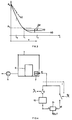
- an inventive apparatus comprises a test cavity 1 with a sealingly closable cover 3.
- a vacuum pump 5 connected to the test cavity 1 which may be a drag pump or a rotational piston valve pump or a diffusion pump or a turbo vacuum pump as a turbo molecular pump. This depends on the degree of vacuum which shall be established within cavity 1.
- a vacuum pressure sensor 7 as e.g. a Pirani sensor, which measures the pressure prevailing in the test cavity 1.
- At least one closed container 9, which is filled at least to some extent with a filling product containing at least one liquid component is introduced through opened cover 3 into the test cavity 1 which is then sealingly closed.
- the pressure in volume V is lowered at least down to the value p V which accords to the vapour pressure of the liquid component within the filling good of the container 9. It is advisable to select a vacuum pump 5 which enables to evacuate the test cavity 1 down to a pressure which is at least one, preferably two and even more preferred three decades lower than the vapour pressure p v of the liquid content of the filling product.
- the test is preferably performed at room temperature, i.e. at a temperature T of about 20°C. If the liquid content is water then the vapour pressure p v of water at room temperature is about 20 mbar and it then is preferred to provide an evacuation pump 5 which is able to evacuate the test cavity to about 10 -2 mbar.
- the pressure sensor 7 is operationally connected to an evaluating unit 15, whereat especially leak indicative threshold values are preset, as schematically shown by means of a presetting unit 17.
- the output of the evaluation unit 15 is a two-state signal indicating leaky or not leaky.
- the output of the vacuum sensor 7 is input to a storage unit 19, controlled by a timing control signal s 1 , as schematically shown via switch S. According to fig. 3 this is performed at a first point in time t 1 . At a second point in time, according to fig. 3 t 2 , the output of the storage unit 19 and the output of the sensor 7 are connected to respective inputs of a difference forming unit 21, which generates an output signal which accords with the pressure difference ⁇ p of fig. 3.
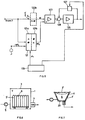
- a further, most preferred realisation of the evaluation electronic is shown in fig. 5.
- the output signal of sensor 7 is input to a conversion unit 121, which comprises, as an input stage, an analogue to digital converter 121a, followed by a digital to analogue converter 121b.
- the output of the converter stage 121 is fed to a difference amplifier unit 123, which additionally receives directly the output signal from sensor 7.
- the output of the difference amplifier unit 123 acts on a further amplifier unit 125, the output of which being superimposed at 128 to a signal from storage unit 127.
- the input of the storage unit 127 is fed from the output of unit 125.
- a timer unit 129 time controls the arrangement.
- the timer unit 129 For storing a first pressure value from sensor 7, according to fig. 3 at time t1, the timer unit 129 enables a conversion cycle at unit 121, so that a reconverted analogue output signal el o appears at the output. Simultaneously, the substantially same signal from sensor 7 is applied as signal el to the second input of unit 123. Thus, at the output of unit 125, a zero signal should appear. Nevertheless, in general a zero-offset signal will appear at the output of unit 125, which signal is stored in the storing unit 127, enabled by the timing unit 129.
- the pressure prevailing in the volume V of the test cavity 1 will have just from the beginning of operating the vacuum pump 5 a different course. This may easily be detected, e.g. by comparing at a previous point in time t 0 the output signal of sensor 7 with a predetermined threshold value (not shown), and if such threshold value is not reached by the actual pressure, the effect of the vacuum pump 5 on test cavity 1 is disabled. This to avoid that, with a larger leak, a huge amount of content of the container is suctioned into the test cavity and contaminates that cavity.
- the proposed method accurately functions largely independently from the volume V between test cavity 1 and the at least one container to be tested. This allows, according to fig. 6, to simultaneously test batches 9' of containers 9, thereby maintaining accuracy of detecting whether one or more than one of the containers 9 leak. Further, the fact that detection accuracy is not critical with respect to difference volume V leads to the possibility of providing one test cavity 1 for a multitude of differently shaped and different-volume containers 9 to be tested therein.
- a test cavity 1' with cover 3' is provided which snugly fits with the shape of the container 9.
- protrusions 20 prevent that by effect of the evacuation the walls of the container are firmly suctioned on to the inner wall of the test cavity and thus make sure that there remains a volume V between container and test cavity wall for being evacuated according to the invention.
- Such protrusions 20 may be realised by a mesh or grid inlay or, and preferably, by mechanically roughening the inner wall of the cavity, so that micro-embossments sustain the wall of the container, thereby leaving a continuous interspace as volume V.
- fig. 9 the method and apparatus according to the present invention may be used to monitor huge tanks with respect to leakage.
- a tank with double-wall namely with an inner wall 23 and an outer wall 25. Testing tightness of both these walls is performed by using the intermediate volume of the two walls, as volume V according to fig. 2.
- Such a technique may be applied e.g. for tanks on road or rail vehicles or for huge stationary tank plants, e.g. for gasoline.
- fig. 8 there is shown one half 1a of a test cavity 1 for applying the inventive method in an inventive apparatus on three containers at 29 as on small plastic containers for medical appliance.
- the containers may have flexible walls as the test cavity 1 snugly fits their shape.
- impedance measurement electrodes 32 and 34 integrated in the wall of the cavity 1 and mutually electrically isolated. They are connected to an impedance or, preferably, resistance measuring unit 35. If by applying a vacuum to the test cavity, preferably with a roughened interior wall, liquid filling content is suctioned to the outside of the container wall, this is quickly detected by an abrupt change of impedance measured between the electrodes 32 and 34. The output of the impedance measuring unit 35 disables (not shown) further evacuation of the test cavity 1.
- a test cavity Once a test cavity has been spoiled by outpouring filling good of a leaking container it is cleaned, either by cleaning evacuation and/or pouring with a gas, preferably with nitrogen, and/or by heating.
- a gas preferably with nitrogen
- a feeding line for a flushing or cleaning gas controllably fed from a gas tank 37 to a contaminated test cavity 1, which gas preferably is nitrogen.
- Two cavity halves, 1a according to fig. 8 are sealingly put one upon the other to complete a test cavity 1 according to fig. 2.
- in-line testing of containers shall be performed, for which the present invention is especially suited due to its short measuring cycle, more than one, namely a set of several test cavities is provided, e.g. on a carousel, which are automatically loaded with containers to be tested (not shown) from a conveyor and which perform simultaneously the described testing technique. If one of the containers tested in such cavity is detected to be leaky, then the respective cavity is not reloaded with a further container afterwards, but this cavity is maintained empty during the measuring cycle on a next set of containers. Meanwhile, the cavity kept unloaded is cleaned, as was described, either by evacuation and/or gas flushing and/or heating.
- a component is to be selected for defining the vapour pressure, which component is liquid enough to penetrate smallest leaks.
Landscapes
- Physics & Mathematics (AREA)
- General Physics & Mathematics (AREA)
- Examining Or Testing Airtightness (AREA)
- Filling Or Discharging Of Gas Storage Vessels (AREA)
Priority Applications (52)
| Application Number | Priority Date | Filing Date | Title |
|---|---|---|---|
| EP97108430A EP0791814A3 (fr) | 1997-05-26 | 1997-05-26 | Méthode pour tester les fuites et appareil pour tester les fuites |
| US08/862,993 US5907093A (en) | 1997-05-26 | 1997-05-27 | Method for leak testing and leak testing apparatus |
| KR1020057004180A KR100649266B1 (ko) | 1997-05-26 | 1998-03-10 | 누설되지 않는 용기의 제조 장치 |
| RU99127446/28A RU2224987C2 (ru) | 1997-05-26 | 1998-03-10 | Способ и устройство для испытания герметичности |
| AU62270/98A AU741250B2 (en) | 1997-05-26 | 1998-03-10 | Method and apparatus for leak testing |
| KR1020057004174A KR100647886B1 (ko) | 1997-05-26 | 1998-03-10 | 누설 검사 방법 및 누설되지 않는 밀폐 용기의 제조 방법 |
| KR1020057004173A KR100649263B1 (ko) | 1997-05-26 | 1998-03-10 | 누설 검사 방법 및 장치 |
| KR1020057004179A KR100647888B1 (ko) | 1997-05-26 | 1998-03-10 | 누설되지 않는 용기의 제조 방법 |
| CNB2003101209800A CN1232811C (zh) | 1997-05-26 | 1998-03-10 | 泄漏测试的方法与装置 |
| PT98904340T PT1021697E (pt) | 1997-05-26 | 1998-03-10 | Metodo e aparelho para realizacao de ensaios de estanquicidade |
| RU2003132449/28A RU2251673C1 (ru) | 1997-05-26 | 1998-03-10 | Способ и устройство для испытания герметичности |
| KR1020057004176A KR100649264B1 (ko) | 1997-05-26 | 1998-03-10 | 충전된 밀폐 용기의 제조 방법 |
| CNB200310120982XA CN1223837C (zh) | 1997-05-26 | 1998-03-10 | 泄漏测试的方法与装置 |
| DK98904340T DK1021697T3 (da) | 1997-05-26 | 1998-03-10 | Fremgangsmåde og apparatus til lækageprövning |
| EP04013838A EP1469295A3 (fr) | 1997-05-26 | 1998-03-10 | Méthode et appareil pour tester une fuite |
| EP10181176.8A EP2293037A3 (fr) | 1997-05-26 | 1998-03-10 | Procédé et appareil de test de fuite |
| CNA2003101209849A CN1519553A (zh) | 1997-05-26 | 1998-03-10 | 泄漏测试的方法与装置 |
| JP50040399A JP2002500764A (ja) | 1997-05-26 | 1998-03-10 | リークテストのための方法および装置 |
| CA2648041A CA2648041C (fr) | 1997-05-26 | 1998-03-10 | Procede et appareil pour realiser des essais d'etancheite |
| RU2003132453/28A RU2290618C2 (ru) | 1997-05-26 | 1998-03-10 | Способ изготовления герметичных сосудов (варианты) и устройство для испытания герметичности |
| ES98904340T ES2231961T3 (es) | 1997-05-26 | 1998-03-10 | Procedimiento y aparato para realizar ensayos de estanqueidad. |
| CNB988055155A CN1322320C (zh) | 1997-05-26 | 1998-03-10 | 泄漏测试的方法及装置 |
| AT98904340T ATE280944T1 (de) | 1997-05-26 | 1998-03-10 | Verfahren und vorrichtung zur leckprüfung |
| RU2003132451/28A RU2252403C1 (ru) | 1997-05-26 | 1998-03-10 | Способ испытания герметичности |
| KR1020057004175A KR100647887B1 (ko) | 1997-05-26 | 1998-03-10 | 충전된 밀폐 용기의 제조 방법 |
| KR1019997010962A KR100633873B1 (ko) | 1997-05-26 | 1998-03-10 | 누설 검사 방법 및 장치 |
| CNB2003101209798A CN1224832C (zh) | 1997-05-26 | 1998-03-10 | 泄漏测试的方法与装置 |
| CA002291181A CA2291181C (fr) | 1997-05-26 | 1998-03-10 | Procede et appareil pour realiser des essais d'etancheite |
| KR1020057004178A KR100649265B1 (ko) | 1997-05-26 | 1998-03-10 | 누설되지 않는 밀폐 용기의 제조 방법 및 누설 검사 장치 |
| CNB2003101209815A CN100442038C (zh) | 1997-05-26 | 1998-03-10 | 泄漏测试的方法与装置 |
| RU2003132450/28A RU2290617C2 (ru) | 1997-05-26 | 1998-03-10 | Способ испытания герметичности |
| CNB2003101209834A CN1285897C (zh) | 1997-05-26 | 1998-03-10 | 制造封闭填充的不泄漏容器的方法 |
| DE69827287T DE69827287T2 (de) | 1997-05-26 | 1998-03-10 | Verfahren und vorrichtung zur leckprüfung |
| EP98904340A EP1021697B1 (fr) | 1997-05-26 | 1998-03-10 | Procede et appareil pour realiser des essais d'etancheite |
| PCT/IB1998/000309 WO1998054560A1 (fr) | 1997-05-26 | 1998-03-10 | Procede et appareil pour realiser des essais d'etancheite |
| RU2003132452/28A RU2287793C2 (ru) | 1997-05-25 | 1998-03-10 | Способ испытания герметичности |
| US10/950,512 US7000456B2 (en) | 1997-05-26 | 2004-09-28 | Method for leak testing and leak testing apparatus |
| US11/267,190 US7260981B2 (en) | 1997-03-26 | 2005-11-07 | Method for leak testing and leak testing apparatus |
| US11/828,495 US7454957B2 (en) | 1997-05-26 | 2007-07-26 | Method for leak testing and leak testing apparatus |
| JP2007229346A JP4351277B2 (ja) | 1997-05-26 | 2007-09-04 | リークテストのための方法および装置 |
| JP2007229343A JP4351276B2 (ja) | 1997-05-26 | 2007-09-04 | リークテストのための方法および装置 |
| JP2007229344A JP2007316086A (ja) | 1997-05-26 | 2007-09-04 | リークテストのための方法および装置 |
| JP2007229339A JP4351273B2 (ja) | 1997-05-26 | 2007-09-04 | リークテストのための方法および装置 |
| JP2007229340A JP4351274B2 (ja) | 1997-05-26 | 2007-09-04 | リークテストのための方法および装置 |
| JP2007229341A JP2007316084A (ja) | 1997-05-26 | 2007-09-04 | リークテストのための方法および装置 |
| JP2007229342A JP4351275B2 (ja) | 1997-05-26 | 2007-09-04 | リークテストのための方法および装置 |
| JP2007229345A JP2007316087A (ja) | 1997-05-26 | 2007-09-04 | リークテストのための方法および装置 |
| JP2007229347A JP4351278B2 (ja) | 1997-05-26 | 2007-09-04 | リークテストのための方法および装置 |
| JP2010040338A JP2010117376A (ja) | 1997-05-26 | 2010-02-25 | リークテストのための方法および装置 |
| JP2010075647A JP2010151846A (ja) | 1997-05-26 | 2010-03-29 | リークテストのための方法および装置 |
| US13/913,885 US20130291625A1 (en) | 1997-05-26 | 2013-06-10 | Method for leak testing and leak testing apparatus |
| US14/477,074 US9091612B2 (en) | 1997-05-26 | 2014-09-04 | Method for leak testing and leak testing apparatus |
Applications Claiming Priority (2)
| Application Number | Priority Date | Filing Date | Title |
|---|---|---|---|
| EP97108430A EP0791814A3 (fr) | 1997-05-26 | 1997-05-26 | Méthode pour tester les fuites et appareil pour tester les fuites |
| US08/862,993 US5907093A (en) | 1997-05-26 | 1997-05-27 | Method for leak testing and leak testing apparatus |
Publications (2)
| Publication Number | Publication Date |
|---|---|
| EP0791814A2 true EP0791814A2 (fr) | 1997-08-27 |
| EP0791814A3 EP0791814A3 (fr) | 1997-11-26 |
Family
ID=26145472
Family Applications (4)
| Application Number | Title | Priority Date | Filing Date |
|---|---|---|---|
| EP97108430A Withdrawn EP0791814A3 (fr) | 1997-03-26 | 1997-05-26 | Méthode pour tester les fuites et appareil pour tester les fuites |
| EP98904340A Expired - Lifetime EP1021697B1 (fr) | 1997-05-26 | 1998-03-10 | Procede et appareil pour realiser des essais d'etancheite |
| EP10181176.8A Withdrawn EP2293037A3 (fr) | 1997-05-26 | 1998-03-10 | Procédé et appareil de test de fuite |
| EP04013838A Withdrawn EP1469295A3 (fr) | 1997-05-26 | 1998-03-10 | Méthode et appareil pour tester une fuite |
Family Applications After (3)
| Application Number | Title | Priority Date | Filing Date |
|---|---|---|---|
| EP98904340A Expired - Lifetime EP1021697B1 (fr) | 1997-05-26 | 1998-03-10 | Procede et appareil pour realiser des essais d'etancheite |
| EP10181176.8A Withdrawn EP2293037A3 (fr) | 1997-05-26 | 1998-03-10 | Procédé et appareil de test de fuite |
| EP04013838A Withdrawn EP1469295A3 (fr) | 1997-05-26 | 1998-03-10 | Méthode et appareil pour tester une fuite |
Country Status (14)
| Country | Link |
|---|---|
| US (1) | US5907093A (fr) |
| EP (4) | EP0791814A3 (fr) |
| JP (10) | JP2002500764A (fr) |
| KR (7) | KR100647888B1 (fr) |
| CN (7) | CN1285897C (fr) |
| AT (1) | ATE280944T1 (fr) |
| AU (1) | AU741250B2 (fr) |
| CA (2) | CA2648041C (fr) |
| DE (1) | DE69827287T2 (fr) |
| DK (1) | DK1021697T3 (fr) |
| ES (1) | ES2231961T3 (fr) |
| PT (1) | PT1021697E (fr) |
| RU (6) | RU2290617C2 (fr) |
| WO (1) | WO1998054560A1 (fr) |
Cited By (11)
| Publication number | Priority date | Publication date | Assignee | Title |
|---|---|---|---|---|
| EP2293037A2 (fr) | 1997-05-26 | 2011-03-09 | Martin Lehmann | Procédé et appareil de test de fuite |
| WO2012107597A2 (fr) | 2012-05-02 | 2012-08-16 | Wilco Ag | Procédé de détection d'un gaz propulseur |
| WO2011012730A3 (fr) * | 2010-08-10 | 2013-03-28 | Wilco Ag | Procédé et appareil pour soumettre des contenants à un essai d'étanchéité |
| WO2013182251A1 (fr) * | 2012-06-08 | 2013-12-12 | Wilco Ag | Contrôle de fuite de récipient multi-stade |
| US8692186B2 (en) | 2010-08-10 | 2014-04-08 | Wilco Ag | Method and apparatus for leak testing containers |
| CN103884479A (zh) * | 2014-04-11 | 2014-06-25 | 慈溪市三洋电子有限公司 | 一种测试阀门密封性能的方法及系统 |
| CN104122038A (zh) * | 2013-04-23 | 2014-10-29 | 深圳市海洋王照明工程有限公司 | 密封检测装置及其检测方法 |
| CN105020403A (zh) * | 2015-06-05 | 2015-11-04 | 苏州纽威阀门股份有限公司 | 一种阀门 |
| CN105179718A (zh) * | 2015-09-21 | 2015-12-23 | 苏州纽威阀门股份有限公司 | 一种阀门 |
| CN106383011A (zh) * | 2016-08-19 | 2017-02-08 | 上海科勒电子科技有限公司 | 漏水传感器 |
| IT201800005260A1 (it) * | 2018-05-11 | 2019-11-11 | Metodo per il controllo di tenuta di una cella di una batteria e relativo sistema di controllo |
Families Citing this family (91)
| Publication number | Priority date | Publication date | Assignee | Title |
|---|---|---|---|---|
| US6082184A (en) * | 1997-05-27 | 2000-07-04 | Martin Lehmann | Method for leak testing and leak testing apparatus |
| KR100633873B1 (ko) * | 1997-05-26 | 2006-10-13 | 마틴 레흐만 | 누설 검사 방법 및 장치 |
| US6662631B2 (en) * | 1998-08-28 | 2003-12-16 | Interuniversitair Microelektronica Centrum | Method and apparatus for characterization of porous films |
| US6584828B2 (en) | 1999-12-17 | 2003-07-01 | Atc, Inc. | Method and apparatus of nondestructive testing a sealed product for leaks |
| US6308556B1 (en) | 1999-12-17 | 2001-10-30 | Atc, Inc. | Method and apparatus of nondestructive testing a sealed product for leaks |
| US6526809B2 (en) | 2000-03-30 | 2003-03-04 | Cincinnati Test Systems, Inc. | Method for identifying leaks in a sealed package having a liquid therein |
| CN101126673B (zh) * | 2000-09-26 | 2012-08-15 | 马丁·莱曼 | 一种装配和测试封闭容器的方法 |
| DK1320738T3 (da) * | 2000-09-26 | 2009-06-15 | Martin Lehmann | Fremgangsmåde og apparat til tæthedsprövning af lukkede beholdere |
| EP1585983B1 (fr) | 2002-10-31 | 2008-08-13 | Martin Lehmann | Procede et appareil de fabrication et de verification ultrasonore des zones de liaison de recipients hermetiquement fermes pour produits alimentaires |
| CA2519483A1 (fr) * | 2003-03-17 | 2004-09-30 | Johnson & Johnson Vision Care, Inc. | Detecteur de fuites en ligne |
| RU2253095C2 (ru) * | 2003-08-06 | 2005-05-27 | Открытое акционерное общество "Ракетно-космическая корпорация "Энергия" им. С.П. Королева" | Способ определения расходных характеристик дренажных устройств отсека летательного аппарата и система для его осуществления |
| RU2267108C2 (ru) * | 2003-08-06 | 2005-12-27 | Открытое акционерное общество "Ракетно-космическая корпорация "Энергия" им. С.П. Королева" | Способ определения расходных характеристик дренажных устройств корпуса летательного аппарата и система для его осуществления |
| US7266993B2 (en) * | 2004-06-04 | 2007-09-11 | Air Logic Power Systems, Inc. | Container leak detection apparatus and method |
| EP1848967B1 (fr) * | 2005-02-02 | 2012-02-08 | Mocon, Inc. | Instrument et procede permettant de detecter et rapporter la taille des fuites dans un emballage hermetiquement ferme |
| US7289863B2 (en) * | 2005-08-18 | 2007-10-30 | Brooks Automation, Inc. | System and method for electronic diagnostics of a process vacuum environment |
| KR101195942B1 (ko) | 2006-03-20 | 2012-10-29 | 삼성전자주식회사 | 카메라 보정 방법 및 이를 이용한 3차원 물체 재구성 방법 |
| JP4816931B2 (ja) * | 2006-06-27 | 2011-11-16 | 東洋製罐株式会社 | 容器の気密性検査方法及びその方法に用いられる容器の気密性検査システム |
| US8366690B2 (en) * | 2006-09-19 | 2013-02-05 | Kci Licensing, Inc. | System and method for determining a fill status of a canister of fluid in a reduced pressure treatment system |
| CN101511277B (zh) * | 2006-09-19 | 2013-05-22 | 凯希特许有限公司 | 具有阻塞清除和双区压力保护能力的减压治疗系统 |
| RU2428208C2 (ru) * | 2007-02-09 | 2011-09-10 | КейСиАй Лайсензинг Инк. | Система и способ управления пониженным давлением на участке ткани |
| AU2008219034B2 (en) * | 2007-02-20 | 2012-01-19 | Solventum Intellectual Properties Company | System and method for distinguishing leaks from a disengaged canister condition in a reduced pressure treatment system |
| RU2371689C2 (ru) * | 2007-10-01 | 2009-10-27 | Российская Федерация, от имени которой выступает государственный заказчик - Государственная корпорация по атомной энергии "Росатом" | Способ испытания на герметичность проходных гермоэлементов в сосудах и устройство для его осуществления |
| US8134372B2 (en) | 2007-11-02 | 2012-03-13 | King Kegan Y | Pressure tank fault detector and method |
| CN103542987B (zh) * | 2008-03-31 | 2017-05-10 | Atmi包装公司 | 用于柔性容器完整性测试的设备和方法 |
| EP2992912B1 (fr) * | 2008-08-08 | 2017-11-22 | KCI Licensing, Inc. | Systèmes de traitement à pression réduite avec commande du réservoir |
| US8555704B2 (en) * | 2008-10-20 | 2013-10-15 | Agilent Technologies, Inc. | Calibration systems and methods for tracer gas leak detection |
| DE102009009370A1 (de) * | 2009-02-18 | 2010-08-19 | Inficon Gmbh | Verfahren zur Funktionsprüfung eines Lecksuchgerätes |
| PT2449356E (pt) * | 2009-07-01 | 2013-08-27 | Wilco Ag | Método para ensaio de fugas em recipientes fechados, cheios, pelo menos parcialmente, de gás |
| EP2317299A1 (fr) * | 2009-10-28 | 2011-05-04 | Brand Gmbh + Co Kg | Procédé de contrôle de l'étanchéité de pipettes à piston élévateur maintenues manuellement et dispositif de contrôle de l'étanchéité correspondant |
| PL2502043T3 (pl) * | 2009-11-20 | 2018-08-31 | Packaging Technologies & Inspection Llc | Stan próżni spoczynkowej dla sposobu i układu do testowania wycieków w oparciu o utratę podciśnienia |
| KR101180779B1 (ko) * | 2010-07-05 | 2012-09-10 | 주식회사 이노칩테크놀로지 | 공진 장치의 리크 검출 방법 |
| CN103069261B (zh) * | 2010-07-05 | 2016-02-10 | 国立大学法人山口大学 | 漏泄检查装置及漏泄检查方法 |
| CN102071967B (zh) * | 2011-01-26 | 2013-06-05 | 中国科学院武汉岩土力学研究所 | 一种盐腔充填模拟装置 |
| JP5664521B2 (ja) | 2011-10-26 | 2015-02-04 | トヨタ自動車株式会社 | リークテスト方法およびリークテスト装置 |
| DE102011086486B4 (de) * | 2011-11-16 | 2023-01-19 | Inficon Gmbh | Vorrichtung und Verfahren zur schnellen Lecksuche an formsteifen/schlaffen Verpackungen ohne Zusatz von Prüfgas |
| CN102607772A (zh) * | 2012-03-06 | 2012-07-25 | 常熟金像电子有限公司 | 一种曝光机曝光台密合度的测试方法 |
| DE102012210040A1 (de) * | 2012-06-14 | 2013-12-19 | Inficon Gmbh | Prüfvorrichtung mit einem Prüfgasbehälter |
| US8534120B1 (en) | 2012-09-14 | 2013-09-17 | Advanced Scientifics, Inc. | Test system and method for flexible containers |
| DE102012217945A1 (de) * | 2012-10-01 | 2014-04-03 | Inficon Gmbh | Folienkammer und Verfahren zur Leckagedetektion an einem nicht formstarren Prüfling |
| US20150153245A1 (en) * | 2012-10-24 | 2015-06-04 | Pall Technology Uk Limited | Integrity testing apparatus and related methods |
| US9038257B2 (en) | 2012-10-31 | 2015-05-26 | Martin Lehmann | High-speed loading/unloading of objects |
| DE102012220108A1 (de) | 2012-11-05 | 2014-05-22 | Inficon Gmbh | Verfahren zur Prüfung einer Dichtheitsprüfanlage |
| CN102967425A (zh) * | 2012-12-12 | 2013-03-13 | 天津渤海化工有限责任公司天津碱厂 | 一种开车前氧气管线开关阀泄露的测试方法 |
| CN103016959A (zh) * | 2012-12-12 | 2013-04-03 | 天津渤海化工有限责任公司天津碱厂 | 一种开车前氧气管线泄露的测试方法 |
| JP6244758B2 (ja) * | 2013-09-06 | 2017-12-13 | 富士通株式会社 | 携帯端末装置および検出プログラム |
| US10519415B2 (en) | 2013-12-10 | 2019-12-31 | Abec, Inc. | Attachment device for single use containers |
| DE102014202596B4 (de) | 2014-02-13 | 2024-03-21 | Robert Bosch Gmbh | Verfahren und Vorrichtung zur Dichtigkeitsprüfung eines abgeschlossenen Behälters |
| CN103926040B (zh) * | 2014-03-17 | 2017-06-20 | 惠州Tcl移动通信有限公司 | 一种用于检测防水性能的测试工装 |
| DE102014205027A1 (de) * | 2014-03-18 | 2015-09-24 | Inficon Gmbh | Evakuierbare flexible Leckageprüfkammer |
| JP6519979B2 (ja) * | 2014-03-31 | 2019-05-29 | 東洋製罐グループホールディングス株式会社 | 欠陥検査装置及び欠陥検査方法 |
| DE102015110328A1 (de) * | 2015-06-26 | 2016-12-29 | Volkswagen Aktiengesellschaft | Funktionale Komponente |
| CN104949811B (zh) * | 2015-07-06 | 2018-03-06 | 江苏科技大学 | 一种柴油机填料函密封性检测装置 |
| DE102015214345A1 (de) | 2015-07-29 | 2017-02-02 | Robert Bosch Gmbh | Prüfvorrichtung zur Überprüfung einer Dichtheit von Behältnissen sowie ein Verfahren dafür |
| DE102015217598A1 (de) * | 2015-09-15 | 2017-03-16 | Inficon Gmbh | Leckdetektion beim Evakuieren einer Prüfkammer oder eines Prüflings |
| DE102015226360A1 (de) | 2015-12-21 | 2017-06-22 | Inficon Gmbh | Grobleckmessung eines inkompressiblen Prüflings in einer Folienkammer |
| CN107631844A (zh) * | 2016-07-18 | 2018-01-26 | 万向二三股份公司 | 一种软包锂电池的密封性检测方法 |
| CN106370365B (zh) * | 2016-08-16 | 2019-07-02 | 中国科学院化学研究所 | 液体封装装置的检漏方法 |
| CN106275630B (zh) * | 2016-09-14 | 2018-05-11 | 中国大冢制药有限公司 | 软袋包装药品漏液检测设备 |
| RU2642121C1 (ru) * | 2016-10-10 | 2018-01-24 | Общество с ограниченной ответственностью "Научно-производственная фирма "Реал-Шторм" | Способ определения полной и остаточной объемной деформации сосуда (баллона) |
| US10422716B2 (en) * | 2016-12-08 | 2019-09-24 | Pall Corporation | Method and system for leak testing |
| PL3563133T3 (pl) * | 2016-12-27 | 2025-02-24 | Packaging Technologies & Inspection Llc | Dynamiczny sposób wykrywania nieszczelności z utratą podciśnienia i urządzenie |
| CN108267280A (zh) * | 2016-12-30 | 2018-07-10 | 致茂电子(苏州)有限公司 | 气密性检测方法及气密性检测装置 |
| DE102017200850A1 (de) * | 2017-01-13 | 2018-07-19 | Robert Bosch Gmbh | Prüfvorrichtung, insbesondere für pharmazeutische Erzeugnisse, mit verbesserter Messqualität |
| KR101935394B1 (ko) * | 2017-06-01 | 2019-04-03 | 주식회사 씨케이엘 | 제품 테스트 장치 및 이를 갖는 제품 테스트 설비 |
| BR112020006566B1 (pt) | 2017-10-03 | 2023-03-21 | Abec, Inc | Sistema de reação descartável |
| CN107905991A (zh) * | 2017-11-13 | 2018-04-13 | 上海华力微电子有限公司 | 一种自动检知泵内漏水的侦测系统 |
| CN107991040A (zh) * | 2017-12-01 | 2018-05-04 | 遵义市产品质量检验检测院 | 一种智能压力容器泄露检测系统 |
| DE102017222308A1 (de) * | 2017-12-08 | 2019-06-13 | Inficon Gmbh | Verfahren zur Leckprüfung mit einer Folienkammer mit belüftetem Messvolumen |
| CN108414230B (zh) * | 2018-02-14 | 2019-09-20 | 清华大学 | 一种内燃机早燃检测方法 |
| FR3081050B1 (fr) * | 2018-05-09 | 2020-05-22 | Ateq | Installation de detection de fuite, procede, utilisation, et moyens de stockage de programme d'ordinateur correspondants. |
| CN108761206B (zh) * | 2018-06-28 | 2024-05-14 | 江苏瑞能氟材料科技有限公司 | 一种在线电阻温度压力监控预警仪 |
| CN109145420B (zh) * | 2018-08-08 | 2022-12-16 | 中国船舶重工集团公司第七一九研究所 | 基于汽动设备空气隔离的压强建模方法 |
| CN109443652B (zh) * | 2018-12-16 | 2024-04-26 | 山西汾西重工有限责任公司 | 深海航行器主推电机水压试验漏水检测电路及检测方法 |
| IT201900006922A1 (it) | 2019-05-16 | 2020-11-16 | Ft System Srl | Metodo ed apparato per stabilire la presenza di fessure in contenitori sigillati |
| US12226200B2 (en) | 2019-05-30 | 2025-02-18 | Olympus Corporation | Method for diagnosing gastro esophageal reflux disease |
| CN110320942B (zh) * | 2019-05-31 | 2022-10-11 | 吉林省农业科学院 | 开路式动物呼吸测热装置 |
| DE102019121462B4 (de) * | 2019-08-08 | 2021-12-09 | Inficon Gmbh | Verfahren zur Dichtheitsprüfung eines flüssigkeitsgefüllten Prüflings |
| DE102020102154A1 (de) * | 2019-10-28 | 2021-04-29 | Celina Eidmann | Vorrichtung und Verfahren zur Sicherung der Ladung von Transportmitteln mit Planenaufbauten |
| CN110726508A (zh) * | 2019-10-31 | 2020-01-24 | 广东合立鼎峰科技有限公司 | 一种基于自动抽空系统的真空度及真空泄露的检测方法 |
| JP7510791B2 (ja) * | 2020-06-11 | 2024-07-04 | 株式会社フクダ | エアリークテスト装置 |
| CN111929012A (zh) * | 2020-07-03 | 2020-11-13 | 安徽皖仪科技股份有限公司 | 一种软包装气密性检测系统及方法 |
| KR20220011903A (ko) | 2020-07-22 | 2022-02-03 | 삼성전자주식회사 | 식기 세척기 |
| EP4226743B1 (fr) * | 2020-10-05 | 2026-05-13 | Signify Holding B.V. | Système de luminaire et procédé pour déterminer l'entrée d'eau dans un luminaire |
| CN112353394B (zh) * | 2020-11-11 | 2024-05-17 | 深圳市科瑞康实业有限公司 | 一种盆底肌压力的检测装置及其校准方法 |
| JP7392640B2 (ja) * | 2020-11-27 | 2023-12-06 | 株式会社島津製作所 | 気体試料導入装置、および、気体試料導入装置のリークチェック方法 |
| CN113252257B (zh) * | 2021-06-10 | 2021-09-10 | 山东奥扬新能源科技股份有限公司 | 一种电池包气密性检测设备 |
| CN113532770B (zh) * | 2021-07-26 | 2023-05-12 | 重庆工商大学 | 一种注射剂玻璃容器微孔泄漏量的测量设备及方法 |
| CN114235308A (zh) * | 2021-12-09 | 2022-03-25 | 武汉欧格莱液压动力设备有限公司 | 一种液压元件密封性能检验方法 |
| CN114636531B (zh) * | 2022-03-11 | 2024-02-27 | 四川省药品检验研究院(四川省医疗器械检测中心) | 基于真空度衰减的硬质包装容器密封性的测试装置及方法 |
| TWI853699B (zh) * | 2023-09-06 | 2024-08-21 | 英業達股份有限公司 | 漏液檢測電路、方法及裝置 |
| CN119517813B (zh) * | 2024-12-27 | 2025-11-14 | 上海良薇机电工程有限公司 | 一种特气输送元器件性能测试系统、方法及半导体工艺设备 |
Family Cites Families (29)
| Publication number | Priority date | Publication date | Assignee | Title |
|---|---|---|---|---|
| US857388A (en) * | 1906-06-07 | 1907-06-18 | Edward S Eno | Method for testing filled and closed cans. |
| US2304192A (en) * | 1940-08-16 | 1942-12-08 | Honeywell Regulator Co | Refrigeration of hygroscopic material |
| FR962489A (fr) * | 1947-03-07 | 1950-06-10 | ||
| US2784373A (en) * | 1953-03-02 | 1957-03-05 | Nat Res Corp | High-vacuum device |
| CH418678A (de) * | 1963-06-06 | 1966-08-15 | Balzers Patent Beteilig Ag | Verfahren zur serienmässigen Prüfung geschlossener, gasgefüllter Behälter auf Dichtigkeit |
| US3381523A (en) * | 1965-03-03 | 1968-05-07 | Henry D. Nettles | Method and apparatus for supplying gas under pressure |
| US3751972A (en) * | 1972-08-02 | 1973-08-14 | Applied Fluidics | Leak detector for sealed containers |
| US5333677A (en) * | 1974-04-02 | 1994-08-02 | Stephen Molivadas | Evacuated two-phase head-transfer systems |
| DE2928336B1 (de) * | 1979-07-13 | 1980-12-18 | Pfeiffer Vakuumtechnik | Leckraten-Messeinrichtung |
| US4409817A (en) * | 1981-03-25 | 1983-10-18 | Edwards Jr David | Vacuum leak detector and method |
| US4459843A (en) * | 1982-07-06 | 1984-07-17 | Durham La Moyne W | Apparatus and method for testing containers |
| DE3340353A1 (de) * | 1983-11-08 | 1985-05-15 | Pfanni-Werke Otto Eckart KG, 8000 München | Verfahren und vorrichtung zur bestimmung von undichtigkeiten in dichten behaeltnissen |
| US4542643A (en) * | 1983-11-25 | 1985-09-24 | S. Himmelstein And Company | Fluid leak testing method |
| JPS6256831A (ja) * | 1985-09-05 | 1987-03-12 | Shinkosumosu Denki Kk | 容器の漏洩検知方法と装置 |
| JPS62220774A (ja) * | 1986-03-20 | 1987-09-28 | Agency Of Ind Science & Technol | ビスコシ−ルを用いた軸封装置 |
| EP0257159A3 (fr) * | 1986-08-21 | 1989-04-26 | Nuclear Packaging, Inc. | Drainage de déchets nucléaires |
| US4791806A (en) * | 1987-10-23 | 1988-12-20 | Wade James H | Leak detection system |
| ES2033284T3 (es) * | 1987-10-28 | 1993-03-16 | Martin Lehmann | Procedimiento y dispositivo para comprobar la hermeticidad de un cuerpo hueco y empleo del procedimiento. |
| US5199296A (en) * | 1989-01-27 | 1993-04-06 | Martin Lehmann | Method for reducing test cycle time and for improving measuring accuracy at a leak testing process |
| DE69033002T2 (de) * | 1989-10-02 | 1999-09-02 | Canon K.K. | Belichtungsvorrichtung |
| US5243821A (en) * | 1991-06-24 | 1993-09-14 | Air Products And Chemicals, Inc. | Method and apparatus for delivering a continuous quantity of gas over a wide range of flow rates |
| US5317896A (en) * | 1992-03-13 | 1994-06-07 | American Sterilizer Company | Method of detecting liquid in a sterilization system |
| US5513516A (en) * | 1992-05-01 | 1996-05-07 | Visi-Pack, Inc. | Method and apparatus for leak testing a container |
| CH685887A5 (de) * | 1992-08-12 | 1995-10-31 | Martin Lehmann | Verfahren zur Pruefung von Behaeltnissen Anwendung des Verfahrens sowie Pruefanordnung |
| JPH0772281A (ja) * | 1993-09-03 | 1995-03-17 | Toshiba Corp | 非常用ガス処理装置 |
| CA2113845A1 (fr) * | 1994-01-20 | 1995-07-21 | Edward J. Farkas | Systeme de commande servant a remplir des reservoirs de liquides satures |
| JPH0835452A (ja) * | 1994-07-26 | 1996-02-06 | Hitachi Ltd | エバポパージシステムの診断方法 |
| SE507197C2 (sv) * | 1996-08-26 | 1998-04-20 | Getinge Skaerhamn Ab | Metod att testa luftläckage |
| EP0791814A3 (fr) | 1997-05-26 | 1997-11-26 | Martin Lehmann | Méthode pour tester les fuites et appareil pour tester les fuites |
-
1997
- 1997-05-26 EP EP97108430A patent/EP0791814A3/fr not_active Withdrawn
- 1997-05-27 US US08/862,993 patent/US5907093A/en not_active Expired - Lifetime
-
1998
- 1998-03-10 AT AT98904340T patent/ATE280944T1/de active
- 1998-03-10 KR KR1020057004179A patent/KR100647888B1/ko not_active Expired - Fee Related
- 1998-03-10 CA CA2648041A patent/CA2648041C/fr not_active Expired - Fee Related
- 1998-03-10 CA CA002291181A patent/CA2291181C/fr not_active Expired - Fee Related
- 1998-03-10 CN CNB2003101209834A patent/CN1285897C/zh not_active Expired - Fee Related
- 1998-03-10 CN CNB2003101209815A patent/CN100442038C/zh not_active Expired - Fee Related
- 1998-03-10 RU RU2003132450/28A patent/RU2290617C2/ru not_active IP Right Cessation
- 1998-03-10 CN CNB2003101209800A patent/CN1232811C/zh not_active Expired - Fee Related
- 1998-03-10 DE DE69827287T patent/DE69827287T2/de not_active Expired - Lifetime
- 1998-03-10 CN CNB988055155A patent/CN1322320C/zh not_active Expired - Fee Related
- 1998-03-10 KR KR1020057004180A patent/KR100649266B1/ko not_active Expired - Fee Related
- 1998-03-10 CN CNB2003101209798A patent/CN1224832C/zh not_active Expired - Fee Related
- 1998-03-10 RU RU99127446/28A patent/RU2224987C2/ru not_active IP Right Cessation
- 1998-03-10 KR KR1020057004174A patent/KR100647886B1/ko not_active Expired - Fee Related
- 1998-03-10 RU RU2003132453/28A patent/RU2290618C2/ru not_active IP Right Cessation
- 1998-03-10 RU RU2003132449/28A patent/RU2251673C1/ru not_active IP Right Cessation
- 1998-03-10 KR KR1020057004175A patent/KR100647887B1/ko not_active Expired - Fee Related
- 1998-03-10 KR KR1020057004173A patent/KR100649263B1/ko not_active Expired - Fee Related
- 1998-03-10 KR KR1020057004178A patent/KR100649265B1/ko not_active Expired - Fee Related
- 1998-03-10 AU AU62270/98A patent/AU741250B2/en not_active Ceased
- 1998-03-10 JP JP50040399A patent/JP2002500764A/ja active Pending
- 1998-03-10 EP EP98904340A patent/EP1021697B1/fr not_active Expired - Lifetime
- 1998-03-10 CN CNB200310120982XA patent/CN1223837C/zh not_active Expired - Fee Related
- 1998-03-10 RU RU2003132452/28A patent/RU2287793C2/ru not_active IP Right Cessation
- 1998-03-10 EP EP10181176.8A patent/EP2293037A3/fr not_active Withdrawn
- 1998-03-10 EP EP04013838A patent/EP1469295A3/fr not_active Withdrawn
- 1998-03-10 KR KR1020057004176A patent/KR100649264B1/ko not_active Expired - Fee Related
- 1998-03-10 ES ES98904340T patent/ES2231961T3/es not_active Expired - Lifetime
- 1998-03-10 RU RU2003132451/28A patent/RU2252403C1/ru not_active IP Right Cessation
- 1998-03-10 DK DK98904340T patent/DK1021697T3/da active
- 1998-03-10 PT PT98904340T patent/PT1021697E/pt unknown
- 1998-03-10 CN CNA2003101209849A patent/CN1519553A/zh active Pending
- 1998-03-10 WO PCT/IB1998/000309 patent/WO1998054560A1/fr not_active Ceased
-
2007
- 2007-09-04 JP JP2007229343A patent/JP4351276B2/ja not_active Expired - Fee Related
- 2007-09-04 JP JP2007229339A patent/JP4351273B2/ja not_active Expired - Fee Related
- 2007-09-04 JP JP2007229344A patent/JP2007316086A/ja active Pending
- 2007-09-04 JP JP2007229340A patent/JP4351274B2/ja not_active Expired - Fee Related
- 2007-09-04 JP JP2007229346A patent/JP4351277B2/ja not_active Expired - Fee Related
- 2007-09-04 JP JP2007229342A patent/JP4351275B2/ja not_active Expired - Fee Related
- 2007-09-04 JP JP2007229345A patent/JP2007316087A/ja active Pending
- 2007-09-04 JP JP2007229347A patent/JP4351278B2/ja not_active Expired - Fee Related
- 2007-09-04 JP JP2007229341A patent/JP2007316084A/ja active Pending
Cited By (22)
| Publication number | Priority date | Publication date | Assignee | Title |
|---|---|---|---|---|
| EP2293037A2 (fr) | 1997-05-26 | 2011-03-09 | Martin Lehmann | Procédé et appareil de test de fuite |
| RU2539782C2 (ru) * | 2010-08-10 | 2015-01-27 | Вилко Аг | Способ и установка для испытания контейнеров на утечку |
| WO2011012730A3 (fr) * | 2010-08-10 | 2013-03-28 | Wilco Ag | Procédé et appareil pour soumettre des contenants à un essai d'étanchéité |
| US8692186B2 (en) | 2010-08-10 | 2014-04-08 | Wilco Ag | Method and apparatus for leak testing containers |
| US8975576B2 (en) | 2010-08-10 | 2015-03-10 | Wilco Ag | Method and apparatus for leak testing containers |
| WO2012107597A2 (fr) | 2012-05-02 | 2012-08-16 | Wilco Ag | Procédé de détection d'un gaz propulseur |
| US9970864B2 (en) | 2012-05-02 | 2018-05-15 | Wilco Ag | Method of detecting a propellant gas |
| CN104471365A (zh) * | 2012-06-08 | 2015-03-25 | 威尔科股份公司 | 多阶段容器泄漏测试 |
| WO2013182251A1 (fr) * | 2012-06-08 | 2013-12-12 | Wilco Ag | Contrôle de fuite de récipient multi-stade |
| CN104471365B (zh) * | 2012-06-08 | 2018-12-18 | 威尔科股份公司 | 多阶段容器泄漏测试 |
| US10012560B2 (en) | 2012-06-08 | 2018-07-03 | Wilco Ag | Multistage container leak testing |
| AU2012381819B2 (en) * | 2012-06-08 | 2017-04-13 | Wilco Ag | Multistage container leak testing |
| CN104122038A (zh) * | 2013-04-23 | 2014-10-29 | 深圳市海洋王照明工程有限公司 | 密封检测装置及其检测方法 |
| CN103884479A (zh) * | 2014-04-11 | 2014-06-25 | 慈溪市三洋电子有限公司 | 一种测试阀门密封性能的方法及系统 |
| CN105020403A (zh) * | 2015-06-05 | 2015-11-04 | 苏州纽威阀门股份有限公司 | 一种阀门 |
| CN105020403B (zh) * | 2015-06-05 | 2017-09-12 | 苏州纽威阀门股份有限公司 | 一种阀门 |
| CN105179718B (zh) * | 2015-09-21 | 2017-09-12 | 苏州纽威阀门股份有限公司 | 一种阀门 |
| CN105179718A (zh) * | 2015-09-21 | 2015-12-23 | 苏州纽威阀门股份有限公司 | 一种阀门 |
| CN106383011A (zh) * | 2016-08-19 | 2017-02-08 | 上海科勒电子科技有限公司 | 漏水传感器 |
| CN106383011B (zh) * | 2016-08-19 | 2019-01-22 | 上海科勒电子科技有限公司 | 漏水传感器 |
| IT201800005260A1 (it) * | 2018-05-11 | 2019-11-11 | Metodo per il controllo di tenuta di una cella di una batteria e relativo sistema di controllo | |
| WO2019215339A1 (fr) * | 2018-05-11 | 2019-11-14 | Marposs Societa' Per Azioni | Procédé de test de fuite d'un élément de batterie et système de test de fuite associé |
Also Published As
Similar Documents
| Publication | Publication Date | Title |
|---|---|---|
| US5907093A (en) | Method for leak testing and leak testing apparatus | |
| US6202477B1 (en) | Method for leak testing and leak testing apparatus | |
| KR100633873B1 (ko) | 누설 검사 방법 및 장치 | |
| AU2003200115B2 (en) | Method and Apparatus for Leak Testing | |
| AU759192B2 (en) | Method and apparatus for leak testing | |
| AU2003252204B2 (en) | Method and Apparatus for Leak Testing | |
| AU2003252203A1 (en) | Method and Apparatus for Leak Testing |
Legal Events
| Date | Code | Title | Description |
|---|---|---|---|
| PUAI | Public reference made under article 153(3) epc to a published international application that has entered the european phase |
Free format text: ORIGINAL CODE: 0009012 |
|
| AK | Designated contracting states |
Kind code of ref document: A2 Designated state(s): AT BE CH DE DK ES FI FR GB GR IE IT LI NL PT SE |
|
| PUAL | Search report despatched |
Free format text: ORIGINAL CODE: 0009013 |
|
| AK | Designated contracting states |
Kind code of ref document: A3 Designated state(s): CH LI |
|
| 17P | Request for examination filed |
Effective date: 19971218 |
|
| AKX | Designation fees paid |
Free format text: AT BE CH DE DK ES FI FR GB GR IE IT LI NL PT SE |
|
| RBV | Designated contracting states (corrected) |
Designated state(s): AT BE CH DE DK ES FI FR GB GR IE IT LI NL PT SE |
|
| RBV | Designated contracting states (corrected) |
Designated state(s): AT BE CH DE DK ES FI FR GB GR IE IT LI NL PT SE |
|
| 17Q | First examination report despatched |
Effective date: 20010712 |
|
| STAA | Information on the status of an ep patent application or granted ep patent |
Free format text: STATUS: THE APPLICATION IS DEEMED TO BE WITHDRAWN |
|
| 18D | Application deemed to be withdrawn |
Effective date: 20020123 |