EP0792016A1 - Signalverarbeitungsvorverstärker für eine Vorrichtung für optische Platte - Google Patents
Signalverarbeitungsvorverstärker für eine Vorrichtung für optische Platte Download PDFInfo
- Publication number
- EP0792016A1 EP0792016A1 EP97301230A EP97301230A EP0792016A1 EP 0792016 A1 EP0792016 A1 EP 0792016A1 EP 97301230 A EP97301230 A EP 97301230A EP 97301230 A EP97301230 A EP 97301230A EP 0792016 A1 EP0792016 A1 EP 0792016A1
- Authority
- EP
- European Patent Office
- Prior art keywords
- signal
- gain control
- automatic gain
- unit
- control unit
- Prior art date
- Legal status (The legal status is an assumption and is not a legal conclusion. Google has not performed a legal analysis and makes no representation as to the accuracy of the status listed.)
- Granted
Links
Images

Classifications
-
- G—PHYSICS
- G11—INFORMATION STORAGE
- G11B—INFORMATION STORAGE BASED ON RELATIVE MOVEMENT BETWEEN RECORD CARRIER AND TRANSDUCER
- G11B19/00—Driving, starting, stopping record carriers not specifically of filamentary or web form, or of supports therefor; Control thereof; Control of operating function ; Driving both disc and head
-
- H—ELECTRICITY
- H03—ELECTRONIC CIRCUITRY
- H03G—CONTROL OF AMPLIFICATION
- H03G3/00—Gain control in amplifiers or frequency changers
- H03G3/20—Automatic control
- H03G3/30—Automatic control in amplifiers having semiconductor devices
- H03G3/3005—Automatic control in amplifiers having semiconductor devices in amplifiers suitable for low-frequencies, e.g. audio amplifiers
-
- G—PHYSICS
- G11—INFORMATION STORAGE
- G11B—INFORMATION STORAGE BASED ON RELATIVE MOVEMENT BETWEEN RECORD CARRIER AND TRANSDUCER
- G11B20/00—Signal processing not specific to the method of recording or reproducing; Circuits therefor
- G11B20/10—Digital recording or reproducing
- G11B20/10009—Improvement or modification of read or write signals
Definitions
- the present invention relates to an optical disc system, and more particularly to a signal-processing preamplifier for an optical disc system which is capable of compensating for a signal attenuation generated during a reproduction of signals from an optical disc such as a mini disc or digital video disc due to an instantaneous variation in the rotating speed of the optical disc or particular characteristics of the optical disc.
- FIG. 1 is a block diagram illustrating the configuration of a conventional preamplifier. Referring to Figure 1, an optical disc system is shown which may be an MD or DVD system.
- the optical disc system includes a pick-up unit 10 for reading an optical signal from an optical disc, a radio frequency (RF) amplifier 20 for amplifying the read signal, an equalization amplifier 30 for varying the frequency characteristic of the optical signal in accordance with the kind of optical disc, a signal processing unit 40 for appropriately processing the optical signal output from the equalization amplifier 30, and a preamplifier 50. Since the read signal output from the pick-up unit 10 has a very small amplitude, it is amplified by the RF amplifier 20. The amplified signal is then sent to the equalization amplifier 30 which, in turn, generates a signal having a desired level. The output signal from the equalization amplifier 30 is then sent to the signal processing unit 40.
- RF radio frequency
- the optical disc system has a plurality of equalization amplifiers respectively corresponding to operation modes thereof.
- a DVD system which has at least six operation modes, at least six equalization amplifiers having different equalization characteristics are used.
- An appropriate one of the equalization amplifiers is selected by a mode selection switch 60 in accordance with a selected operation mode.
- a preamplifier for an optical disc system which uses an automatic gain control (AGC) system, thereby obtaining a constant response and a stable output signal for input signals of a certain amplitude.
- AGC automatic gain control
- a preamplifier for an optical disc system including a pick-up unit for reading an optical signal from an optical disc and a signal processing unit for processing the optical signal, comprising: a radio frequency amplifier for amplifying an output signal from the pick-up unit; an automatic gain control unit for amplifying an output signal from the radio frequency amplifier to a desired level; an automatic gain control detector unit coupled at its input terminal to an output terminal of the automatic gain control unit and at its output terminal to an input terminal of the automatic gain control unit, the automatic gain control detector unit serving to rectify an output signal from the automatic gain control unit, to compare the rectified signal with a reference signal having a predetermined level and to send the resultant signal obtained by the comparison to the automatic gain control unit; and a mode selecting unit coupled to the automatic gain control detector unit and adapted to select one of several modes respectively corresponding to different equalization characteristics.
- the preamplifier further comprises an equalization amplifier for stably outputting a particular frequency at a constant level to allow both the automatic gain control unit and the automatic gain control detector unit to adjust characteristics of the particular frequency.
- both the automatic gain control unit and the automatic gain control detector unit serve to adjust characteristics of a particular frequency, thereby stably outputting the particular frequency at a constant level.
- the automatic gain control unit comprises a voltage control amplifier which is controlled by voltage.
- the automatic gain control detector unit comprises:
- FIG 2 an optical disc system using a signal-processing preamplifier according to an embodiment of the present invention is illustrated.
- elements respectively corresponding to those in Figure 1 are denoted by the same reference numerals.
- FIG. 2 is a block diagram illustrating the configuration of the signal-processing preamplifier according to the present invention.
- the optical disc system has a configuration similar to that in Figure 1 except for the configuration of the signal-processing preamplifier. That is, the signal-processing preamplifier 50A of Figure 2 includes an AGC unit 23 for amplifying an output signal from the RF amplifier 20 to a desired level, an AGC detector unit 25 coupled at its input terminal to the output terminal of the AGC unit 23 and at its output terminal to the input terminal of the AGC unit 23, and a mode selecting unit 60 coupled to the AGC detector unit 25.
- An equalization amplifier 30 is also provided which serves to control characteristics of a particular frequency.
- An output signal from the RF amplifier 20 is adjusted to a desired level by the AGC unit 23 and AGC detector unit 25.
- the AGC unit 23 and AGC detector unit 25 operate to perform the function which is achieved by the equalization amplifier of the conventional configuration.
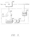
- FIG. 3 is a block diagram illustrating the AGC unit 23 and AGC detector unit 25 of the preamplifier which is denoted by the reference numeral 50A.
- the AGC unit 23 comprises a voltage control amplifier (VCA) 200 for amplifying an input signal Vin.
- the AGC detector unit 25 includes a full-wave rectifier 300 for outputting a full-wave rectified signal in response to the amplified signal from the VCA 200, a logarithmic amplifier 500 for receiving a linear signal, which may be the full-wave rectified signal from the full-wave rectifier 300, and outputting a logarithmically amplified signal, and an integrator 600 for receiving the output signal from the logarithmic amplifier 500 and converting it into a DC signal.
- the AGC detector unit 25 further includes a comparator 400 coupled at one input terminal to an AGC level controlling terminal 90 which provides a reference signal.
- the comparator 400 receives the output signal from the integrator 600 at the other input terminal thereof.
- the comparator 400 sends its output obtained by its comparison operation to the VCA 200.
- embodiments of the present invention provide a signal-processing preamplifier which uses an automatic gain control (AGC) system, thereby obtaining a constant response and a stable output signal for input signals of a certain amplitude.
- AGC automatic gain control
Landscapes
- Engineering & Computer Science (AREA)
- Multimedia (AREA)
- Signal Processing (AREA)
- Control Of Amplification And Gain Control (AREA)
- Optical Recording Or Reproduction (AREA)
- Signal Processing For Digital Recording And Reproducing (AREA)
Applications Claiming Priority (2)
| Application Number | Priority Date | Filing Date | Title |
|---|---|---|---|
| KR1019960004650A KR100206334B1 (ko) | 1996-02-26 | 1996-02-26 | 신호처리를 위한 광디스크의 프리앰프 |
| KR9604650 | 1996-02-26 |
Publications (2)
| Publication Number | Publication Date |
|---|---|
| EP0792016A1 true EP0792016A1 (de) | 1997-08-27 |
| EP0792016B1 EP0792016B1 (de) | 2000-08-16 |
Family
ID=19451787
Family Applications (1)
| Application Number | Title | Priority Date | Filing Date |
|---|---|---|---|
| EP97301230A Expired - Lifetime EP0792016B1 (de) | 1996-02-26 | 1997-02-25 | Signalverarbeitungsvorverstärker für eine Vorrichtung für optische Platte |
Country Status (7)
| Country | Link |
|---|---|
| US (1) | US5745469A (de) |
| EP (1) | EP0792016B1 (de) |
| JP (1) | JP2820676B2 (de) |
| KR (1) | KR100206334B1 (de) |
| CN (1) | CN1086047C (de) |
| DE (1) | DE69702788T2 (de) |
| ES (1) | ES2151228T3 (de) |
Families Citing this family (9)
| Publication number | Priority date | Publication date | Assignee | Title |
|---|---|---|---|---|
| KR100197619B1 (ko) * | 1996-10-04 | 1999-06-15 | 윤종용 | 가변속 재생이 가능한 광디스크시스템의 등화기특성 보상장치 |
| JP4036515B2 (ja) * | 1997-12-22 | 2008-01-23 | 松下電器産業株式会社 | 光ディスク装置 |
| CN1295685C (zh) * | 2003-11-24 | 2007-01-17 | 联发科技股份有限公司 | 光碟机的自动增益控制装置的控制电路 |
| KR100555704B1 (ko) * | 2004-03-09 | 2006-03-03 | 삼성전자주식회사 | 광 재생장치 및 그의 자동 이득 조정방법 |
| JP4244907B2 (ja) * | 2004-10-25 | 2009-03-25 | ソニー株式会社 | 光ディスク装置 |
| KR100790967B1 (ko) * | 2005-07-27 | 2008-01-02 | 삼성전자주식회사 | 자동이득 조절기의 제어전압을 디지털적으로 제어할 수있는 자동이득 조절기 및 제어방법 |
| KR100802125B1 (ko) | 2005-08-22 | 2008-02-11 | 삼성전자주식회사 | 자동이득 제어기 |
| CN100541621C (zh) * | 2006-06-05 | 2009-09-16 | 联发科技股份有限公司 | 自动增益控制器及自动控制输入信号的增益的方法 |
| US20090074993A1 (en) * | 2007-09-18 | 2009-03-19 | Gm Global Technology Operations, Inc. | Active material activated cover |
Citations (6)
| Publication number | Priority date | Publication date | Assignee | Title |
|---|---|---|---|---|
| US3725646A (en) * | 1971-04-19 | 1973-04-03 | Minnesota Mining & Mfg | System for reproducing digital information |
| US4380777A (en) * | 1979-12-18 | 1983-04-19 | Fuji Xerox Co., Ltd. | Keyed AGC circuit for video data transmitting device |
| US4433254A (en) * | 1980-11-27 | 1984-02-21 | Sony Corporation | Level detecting circuit |
| EP0406852A2 (de) * | 1989-07-06 | 1991-01-09 | Hitachi, Ltd. | Verfahren und Gerät zur automatischen Pegelregelung in einem optischen Plattensystem |
| EP0429045A2 (de) * | 1989-11-20 | 1991-05-29 | Matsushita Electric Industrial Co., Ltd. | Wiedergabegerät für optische Platte |
| JPH06334459A (ja) * | 1993-05-18 | 1994-12-02 | Yamaha Corp | ディジタル信号処理装置 |
Family Cites Families (1)
| Publication number | Priority date | Publication date | Assignee | Title |
|---|---|---|---|---|
| JP2852165B2 (ja) * | 1991-11-12 | 1999-01-27 | 三星電子株式会社 | ディジタル磁気記録再生装置のピックアップ信号補正装置 |
-
1996
- 1996-02-26 KR KR1019960004650A patent/KR100206334B1/ko not_active Expired - Fee Related
-
1997
- 1997-02-24 CN CN97102807A patent/CN1086047C/zh not_active Expired - Fee Related
- 1997-02-25 EP EP97301230A patent/EP0792016B1/de not_active Expired - Lifetime
- 1997-02-25 DE DE69702788T patent/DE69702788T2/de not_active Expired - Lifetime
- 1997-02-25 JP JP9040986A patent/JP2820676B2/ja not_active Expired - Fee Related
- 1997-02-25 US US08/805,726 patent/US5745469A/en not_active Expired - Lifetime
- 1997-02-25 ES ES97301230T patent/ES2151228T3/es not_active Expired - Lifetime
Patent Citations (6)
| Publication number | Priority date | Publication date | Assignee | Title |
|---|---|---|---|---|
| US3725646A (en) * | 1971-04-19 | 1973-04-03 | Minnesota Mining & Mfg | System for reproducing digital information |
| US4380777A (en) * | 1979-12-18 | 1983-04-19 | Fuji Xerox Co., Ltd. | Keyed AGC circuit for video data transmitting device |
| US4433254A (en) * | 1980-11-27 | 1984-02-21 | Sony Corporation | Level detecting circuit |
| EP0406852A2 (de) * | 1989-07-06 | 1991-01-09 | Hitachi, Ltd. | Verfahren und Gerät zur automatischen Pegelregelung in einem optischen Plattensystem |
| EP0429045A2 (de) * | 1989-11-20 | 1991-05-29 | Matsushita Electric Industrial Co., Ltd. | Wiedergabegerät für optische Platte |
| JPH06334459A (ja) * | 1993-05-18 | 1994-12-02 | Yamaha Corp | ディジタル信号処理装置 |
Non-Patent Citations (1)
| Title |
|---|
| PATENT ABSTRACTS OF JAPAN vol. 095, no. 003 28 April 1995 (1995-04-28) * |
Also Published As
| Publication number | Publication date |
|---|---|
| US5745469A (en) | 1998-04-28 |
| KR100206334B1 (ko) | 1999-07-01 |
| KR970063155A (ko) | 1997-09-12 |
| ES2151228T3 (es) | 2000-12-16 |
| DE69702788T2 (de) | 2000-12-28 |
| CN1086047C (zh) | 2002-06-05 |
| CN1162816A (zh) | 1997-10-22 |
| JP2820676B2 (ja) | 1998-11-05 |
| JPH09320057A (ja) | 1997-12-12 |
| DE69702788D1 (de) | 2000-09-21 |
| EP0792016B1 (de) | 2000-08-16 |
Similar Documents
| Publication | Publication Date | Title |
|---|---|---|
| EP0425033B1 (de) | Anordnung zum Lesen einer auf einem Informationsträger aufgezeichneten digitalen Information | |
| US4306115A (en) | Automatic volume control system | |
| US5548594A (en) | Compact AGC circuit with stable characteristics | |
| EP0792016A1 (de) | Signalverarbeitungsvorverstärker für eine Vorrichtung für optische Platte | |
| JP2766230B2 (ja) | 受信増幅装置 | |
| JP2773524B2 (ja) | ディジタル移動無線受信機 | |
| US6930553B2 (en) | Automatic gain control device and automatic gain control method | |
| US20030006839A1 (en) | Extended range power detector and amplifier and method | |
| EP0471551A2 (de) | Videoentzerrerschaltung | |
| CA2233624C (en) | Speech-operated noise attenuation device (sonad) control system method and apparatus | |
| US7397873B2 (en) | Adaptive signal weighting system | |
| EP0312266B1 (de) | Gerät zur Wiedergabe von aufgezeichneten Informationen mit Kreuzmodulationsunterdrückung | |
| JP2901372B2 (ja) | ノイズリダクション回路 | |
| JPH0314369A (ja) | フィードバッククランプ回路 | |
| JP3011959B2 (ja) | 信号処理回路 | |
| JP2901371B2 (ja) | ノイズリダクション回路 | |
| JPH02172309A (ja) | 電力増幅装置 | |
| JP3038721B2 (ja) | Rf信号補正回路 | |
| JP2866188B2 (ja) | 集積化フイルタ回路及びこれを用いた信号再生装置 | |
| KR200147519Y1 (ko) | 고주파 안정화 회로 | |
| GB2068197A (en) | Noise reduction circtuits | |
| KR100241755B1 (ko) | 비교 특성이 개선된 필터 증폭기 | |
| JP2004048707A (ja) | 自動利得制御装置、及び自動利得制御方法 | |
| JPH10126175A (ja) | 信号レベル制御装置 | |
| JPH02165743A (ja) | Fmステレオラジオ受信機 |
Legal Events
| Date | Code | Title | Description |
|---|---|---|---|
| PUAI | Public reference made under article 153(3) epc to a published international application that has entered the european phase |
Free format text: ORIGINAL CODE: 0009012 |
|
| 17P | Request for examination filed |
Effective date: 19970312 |
|
| AK | Designated contracting states |
Kind code of ref document: A1 Designated state(s): DE ES GB |
|
| 17Q | First examination report despatched |
Effective date: 19980806 |
|
| GRAG | Despatch of communication of intention to grant |
Free format text: ORIGINAL CODE: EPIDOS AGRA |
|
| GRAG | Despatch of communication of intention to grant |
Free format text: ORIGINAL CODE: EPIDOS AGRA |
|
| GRAH | Despatch of communication of intention to grant a patent |
Free format text: ORIGINAL CODE: EPIDOS IGRA |
|
| GRAH | Despatch of communication of intention to grant a patent |
Free format text: ORIGINAL CODE: EPIDOS IGRA |
|
| GRAA | (expected) grant |
Free format text: ORIGINAL CODE: 0009210 |
|
| AK | Designated contracting states |
Kind code of ref document: B1 Designated state(s): DE ES GB |
|
| REF | Corresponds to: |
Ref document number: 69702788 Country of ref document: DE Date of ref document: 20000921 |
|
| REG | Reference to a national code |
Ref country code: ES Ref legal event code: FG2A Ref document number: 2151228 Country of ref document: ES Kind code of ref document: T3 |
|
| EN | Fr: translation not filed | ||
| PLBE | No opposition filed within time limit |
Free format text: ORIGINAL CODE: 0009261 |
|
| STAA | Information on the status of an ep patent application or granted ep patent |
Free format text: STATUS: NO OPPOSITION FILED WITHIN TIME LIMIT |
|
| 26N | No opposition filed | ||
| REG | Reference to a national code |
Ref country code: GB Ref legal event code: IF02 |
|
| PGFP | Annual fee paid to national office [announced via postgrant information from national office to epo] |
Ref country code: DE Payment date: 20140211 Year of fee payment: 18 |
|
| PGFP | Annual fee paid to national office [announced via postgrant information from national office to epo] |
Ref country code: ES Payment date: 20140218 Year of fee payment: 18 |
|
| PGFP | Annual fee paid to national office [announced via postgrant information from national office to epo] |
Ref country code: GB Payment date: 20140211 Year of fee payment: 18 |
|
| REG | Reference to a national code |
Ref country code: DE Ref legal event code: R119 Ref document number: 69702788 Country of ref document: DE |
|
| GBPC | Gb: european patent ceased through non-payment of renewal fee |
Effective date: 20150225 |
|
| PG25 | Lapsed in a contracting state [announced via postgrant information from national office to epo] |
Ref country code: DE Free format text: LAPSE BECAUSE OF NON-PAYMENT OF DUE FEES Effective date: 20150901 Ref country code: GB Free format text: LAPSE BECAUSE OF NON-PAYMENT OF DUE FEES Effective date: 20150225 |
|
| REG | Reference to a national code |
Ref country code: ES Ref legal event code: FD2A Effective date: 20160329 |
|
| PG25 | Lapsed in a contracting state [announced via postgrant information from national office to epo] |
Ref country code: ES Free format text: LAPSE BECAUSE OF NON-PAYMENT OF DUE FEES Effective date: 20150226 |