EP0793204A2 - Lese-/Schreibeinrichtung für Speichereinrichtungen für elektronisches Geld und ihr Betriebsverfahren - Google Patents
Lese-/Schreibeinrichtung für Speichereinrichtungen für elektronisches Geld und ihr Betriebsverfahren Download PDFInfo
- Publication number
- EP0793204A2 EP0793204A2 EP97103119A EP97103119A EP0793204A2 EP 0793204 A2 EP0793204 A2 EP 0793204A2 EP 97103119 A EP97103119 A EP 97103119A EP 97103119 A EP97103119 A EP 97103119A EP 0793204 A2 EP0793204 A2 EP 0793204A2
- Authority
- EP
- European Patent Office
- Prior art keywords
- electronic money
- writer
- money
- reader
- storing devices
- Prior art date
- Legal status (The legal status is an assumption and is not a legal conclusion. Google has not performed a legal analysis and makes no representation as to the accuracy of the status listed.)
- Withdrawn
Links
- 238000000034 method Methods 0.000 title claims description 16
- 238000012546 transfer Methods 0.000 claims abstract description 56
- 230000015572 biosynthetic process Effects 0.000 claims abstract 3
- 230000004044 response Effects 0.000 claims description 5
- 238000003780 insertion Methods 0.000 claims description 3
- 230000037431 insertion Effects 0.000 claims description 3
- 230000006870 function Effects 0.000 description 14
- 238000004891 communication Methods 0.000 description 11
- 230000008569 process Effects 0.000 description 4
- 238000010586 diagram Methods 0.000 description 3
- 239000003086 colorant Substances 0.000 description 2
- 238000013461 design Methods 0.000 description 2
- RWSOTUBLDIXVET-UHFFFAOYSA-N Dihydrogen sulfide Chemical compound S RWSOTUBLDIXVET-UHFFFAOYSA-N 0.000 description 1
- 239000003795 chemical substances by application Substances 0.000 description 1
- 239000000470 constituent Substances 0.000 description 1
- 238000011161 development Methods 0.000 description 1
- 238000009434 installation Methods 0.000 description 1
- 239000004973 liquid crystal related substance Substances 0.000 description 1
- 238000012986 modification Methods 0.000 description 1
- 230000004048 modification Effects 0.000 description 1
Images

Classifications
-
- G—PHYSICS
- G07—CHECKING-DEVICES
- G07F—COIN-FREED OR LIKE APPARATUS
- G07F7/00—Mechanisms actuated by objects other than coins to free or to actuate vending, hiring, coin or paper currency dispensing or refunding apparatus
- G07F7/08—Mechanisms actuated by objects other than coins to free or to actuate vending, hiring, coin or paper currency dispensing or refunding apparatus by coded identity card or credit card or other personal identification means
- G07F7/0866—Mechanisms actuated by objects other than coins to free or to actuate vending, hiring, coin or paper currency dispensing or refunding apparatus by coded identity card or credit card or other personal identification means by active credit-cards adapted therefor
Definitions
- the present invention relates to a reader/writer for electronic money storing devices and a method of operation of the same, and particularly to a reader/writer for electronic money storing devices and its operational method which are useful for the transfer of electronic money between electronic money storing devices.
- the IC card used in this system incorporates a microprocessor having a communication function and a memory, e.g., EEPROM, for storing a processing program and the balance of electronic money.
- a microprocessor having a communication function and a memory, e.g., EEPROM, for storing a processing program and the balance of electronic money.
- the IC card can be used for electronic money transaction with other IC cards through the electronic money transaction system which includes terminals installed in banks, retail stores, individual residences, etc. linked by a communication line, or by use of such dedicated terminals as electronic wallets that are based on IC cards.
- the above-mentioned card-based electronic wallet is designed to enter an amount of money to be transacted with other IC card by means of a ten-key set provided on it.
- JP-A-08-115389 discloses an electronic wallet system
- JP-A-08-180154 discloses an electronic wallet apparatus
- the electronic wallet system described in the former publication is capable of turning the IC card to the locked state automatically for the sake of enhanced security when it is pulled out of the IC card reader/writer, and unlocking the IC card automatically when it is put into the IC card reader/writer for the sake of the enhanced operability.
- the electronic wallet apparatus described in the latter publication has the provision of IC card protection for an IC card handling POS system for example, in which an illegality code is generated and recorded automatically in an IC card having a transaction record of a retail store or the like when it is pulled out of the register as illegal conduction, thereby provided the apparatus with the enhanced security and operability.
- the above-mentioned object is achieved based on making the appearance (any of the shape, size, color, ornamentation, letters and numbers, or a combination thereof) of the keytops of money selecting keys associative with current bank notes and coins so that the user can have a feel of handling actual money.
- the present invention resides in a reader/writer for electronic money storing devices used for transferring electronic money between multiple electronic money storing devices which can store electronic money, the reader/writer having multiple slots for putting the electronic money storing devices into the reader/writer, money selecting keys (money kind keys) which are used to enter an amount of electronic money to be transferred, and display means which displays the amount of money entered with the money selecting keys (money kind keys).
- the electronic money storing devices can be IC cards.
- the number of slots can be two, and the reader/writer may have a transfer direction key which is used to specify a transfer direction of electronic money between two electronic money storing devices put in the two slots.
- the money selecting keys can have their keytops shaped so as to evoke the association of current bank notes and coins. Alternatively, the money selecting keys can be keys that are displayed on a display window provided on the top of the main body of the reader/writer.
- the reader/writer for electronic money storing devices can operate to display the balance of electronic money in two electronic money storing devices at positions of the display window corresponding to the two slots when the two electronic money storing devices have been put in the two slots.
- the reader/writer for electronic money storing devices can have a transfer direction key which is used to specify a transfer direction of electronic money between two electronic money storing devices by reversing the transfer direction alternately each time it is pushed, with the selected transfer direction being displayed on the display window.
- the reader/writer for electronic money storing devices can have means of entering an amount of electronic money to be transferred between two electronic money storing devices, with the amount of money entered with the amount entry means being displayed on the display window, and the reader/writer transfers the displayed amount of money in the displayed transfer direction in response to the entry of a signal which establishes the amount of money transfer.
- the display window can display the balance of electronic money in two electronic money storing devices after the money transfer between the two electronic money storing devices.
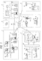
- FIG. 1 denotes a bank branch system
- 2 is a retail -store system
- 3 is an individual user system
- 4 is a vending machine system
- 5 is a bank computing center
- 6 is an electronic money originator
- 7 is a public telephone line
- 10 is an IC card
- 11 is an attached IC card reader/writer unit
- 12 is a banking teller terminal
- 13 is an internal communication line
- 14 is an auto-teller machine (ATM)
- 15 is a value box
- 16 is an electronic money transaction management terminal
- 17 is a relay computer
- 21 is an electronic money POS terminal
- 22 is a usual POS terminal
- 23 is a store controller
- 24 is a center facility
- 25 is a value control/management system
- 26 is a workstation
- 31 is an electronic wallet
- 32 is a personal computer
- 33 is a PC-attached card reader/writer
- 34 is an IC card telephone
- 41 is a built-in IC card reader/writer
- the electronic money transaction system shown in Fig. 1 is made up of a bank branch system 1, retail store system 2 installed in a large retail dealer such as a department store or supermarket, individual user system 3 including a personal computer 32 and IC card telephone 34 all linked through the public telephone line 7, and a vending machine system 4 which is not linked to the telephone line 7.
- the bank branch system 1 also has a direct connection through the leased line 70 to a bank computing center 5, which is connected to an electronic money originator 6.
- IC cards 10 each including a microprocessor with a communication function and a memory, e.g., EEPROM, for storing a processing program and the balance of electronic money, are possessed by individual users, banks, retail stores, vending machines, etc. that are members of the electronic money transaction system.
- a microprocessor with a communication function
- a memory e.g., EEPROM
- the bank branch system 1 which already has the connection with an existing banking teller terminals 12 and auto-teller machine 14 through an internal communication line 13, is further connected with the bank computing center 5 by way of a relay computer 17.
- the banking teller terminals 12 have associated IC card reader/writer units 11 and the auto-teller machine 14 has a built-in IC card reader/writer, and these terminals and machine are connected with a value box 15 by way of an electronic money transaction control terminal 16.
- the bank computing center 5 includes a host accounting system 51 and external accounting system 52, which includes an external system control terminal 53, relay computer 17 and value box 15.
- the retail store system 2 with its POS terminals being generally connected to a center facility 24 through an internal communication line 13 by way of a store controller 23, is further provided with IC card reader/writer units 11 attached to POS terminals 22 or provided with electronic money POS terminals 21.
- the center facility 24 includes a value control/management system 25, work station 26 and value box 15.
- the user system 3 which mainly supports individual users can be as simple as only an electronic wallet 31 with the ability of displaying the balance of electronic money stored in the IC card and possibly with an additional calculator function.
- the user's personal computer 32 has the provision of a PC-type IC card reader/writer 33 for the monetary settlement of electronic money and the ability of linkage to the public telephone line 7.
- the user can also use the IC card telephone 34 which can handle IC cards of electronic money.
- the personal computer 32 and IC card telephone 34 of the individual user system 3 have the provision of two IC card reader/writers so as to perform the electronic money transfer between two IC cards, and it is possible, for example, to transfer electronic money from the husband's IC card to the wife's IC card.
- the vending machine system 4 includes a vending machine 42 having a built-in IC card reader/writer 41.
- the electronic money originator 6 distributes IC cards 10 to banks, retail stores, vending machines and individual users that are members of the system.
- the bank receives electronic money in exchange for currency, and stores the electronic money in the value box 15 in the external accounting system 52.
- the value box 15 stores many IC cards, to which electronic money received from the electronic money originator 6 is distributed and stored. Electronic money stored in the IC cards in the value box 15 of the external accounting system 52 is distributed to IC cards in the value box 15 of the bank branch system 1.
- Each individual member (user) of the electronic money transaction system possesses a distributed IC card 10.
- the user draws one's deposit of bank account in the form of electronic money and stores it in one's IC card 10 by using the banking teller terminals 12 or auto-teller machine 14 in the bank branch system 1.
- the user connects one's personal computer 32 equipped with the PC-type IC card reader/writer 33 or one's card telephone 34 to the bank branch system 1 through the public telephone line 7 and can convert the deposit account money into electronic money and store it in one's IC card 10.
- the user's IC card is linked based on its communication function to a specific IC card in the value box 15 of the bank branch system 1 by way of the banking teller terminal 12, auto-teller machine 14, personal computer 32, or IC card telephone 34.
- Electronic money stored in the IC card 10 of the value box 15 of the bank branch system 1 is transferred and stored in the user's IC card 10 under control of the transaction management terminal 16.
- the balance of electronic money stored in the IC card in the value box 15 of the bank branch system 1 is subtracted-by the amount of electronic money transferred to the user's IC card 10.
- the drawing of deposits of bank accounts of individuals is the same as the convention.
- Electronic money stored in the user's IC card can be transferred back to the IC card in the value box 15 of the bank branch system 1 by way of the banking teller terminal 12, auto-teller machine 14 or personal computer 32, and deposited in the user's bank account.
- the user having electronic money stored in one's IC card as explained above can use the IC card to buy goods and services in retail stores and agents that are members of the system.
- the IC card user who intends to buy goods brings the things to the POS terminal counter in the retail store.
- the clerk operates the POS terminal 21 or 22 to read the barcode label of each thing thereby to enter its price and total the prices of all things, and -charges the total price to the customer.
- the customer who intends to pay for the goods with the IC card puts the card into the card inlet of the electronic money POS terminal 12 or the IC card reader/writer unit 11 attached to the usual POS terminal 22.
- the user's IC card is linked to the relevant IC card in the value box 15 in the center facility 24 of the retail store by way of the store controller 23 and work station 26 over the internal communication line 13.
- Electronic money in the user's IC card is transferred to the IC card in the value box 15 of the center facility 24, and the POS terminal issues a receipt to complete the transaction process.
- Electronic money in the user's IC card is subtracted by the amount of payment, and it is added to electronic money in the IC card of the retail store.
- a small retail shop having only a cash register has the installation of an IC card reader/writer and has a shop's IC card for the cash register, thereby allowing customers to pay with their IC cards through the linkage to the shop's IC card by the IC card reader/writer attached to the cash register.
- Electronic money stored in the shop's IC card can be deposited to the bank account or can also be cashed at the bank.
- these terminals are provided with individual IC cards so that transactions with customer's IC cards are carried out temporarily based on the IC cards of POS terminals, and the contents of IC cards are transferred from the POS terminals to the IC cards in the value box 15 of the center facility 24 afterward when necessary.
- the vending machine 42 included in the electronic money transaction system is provided with the IC card reader/writer 41 built in the machine and its own IC card so that transaction is carried out with a customer's IC card coupled to the IC card reader/writer 41 by the customer.
- Fig. 2 shows the external structure of an electronic wallet 31 which incorporates the reader/writer for electronic money storing devices based on an embodiment of this invention.
- reference numeral 101 denotes a main body of the electronic wallet
- 102 is a flap section
- 103 is a pocket formed on the flap section
- 104 is one slot for IC card 10A
- 105 is another slot for IC card 10B
- 106 is a display window
- 107 is a hinge of the flap section
- 108 is Power key
- 109 Function key
- 110 is Transfer key
- 111 is a set of Money kind keys (Money selecting keys)
- 112 is Enter key
- 113 is Cancel key.
- Fig. 3 shows the electronic wallet 31 with its flap section 102 in closed state
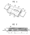
- Fig. 4 shows the bottom of the main body 101.
- Indicated by 114 in Fig. 4 is an opening used to eject the IC card 10B
- Fig. 5 shows the cross section of the electronic wallet taken along the line A-A of Fig. 4, in which symbols "a" and "b" indicate dimensions of the depth of the card slots 104 and 105 for the IC card 10A and 10B, respectively.
- the electronic wallet 31 based on this embodiment of invention consists of a main body 101, a flap section 102 and a hinge 107 which connects these sections.
- Formed in the main body 101 are two card slots 104 and 105 for putting in IC cards 10A and 10B which can store electronic money, a liquid crystal display window 106, Power key 108, Function key 109 used for menu selection, Transfer key 110, Money kind keys 111 used for entering an amount of money transfer, Enter key 112, Cancel key 113, and opening 114 used to eject the IC card 10B.
- a pocket which can contain IC cards.
- one card slot 104 has its depth dimensioned as shown by "a” in Fig. 5 such that at least one third in longitudinal dimension of the IC card 10A is placed horizontally in the main body 101 while another card slot 105 has its depth dimensioned as shown by "b” such that the entirety of the IC card 10B is placed horizontally in the main body 101.
- the IC card 10B can be taken out of the electronic wallet 31 by sliding it backward with a finger through the opening 114.
- the card slot 105 formed in the right side wall of the main body 101 is used for the IC card 10B possessed by the owner of the electronic wallet. Since the whole IC card 10B is accommodated in the main body 101, it does not hamper the carrying of the electronic wallet and is protected from damage and loss (fall off).
- Both IC cards 10A and 10B in their set positions come in contact with the IC card reader/writer equipped in the main body 101, and electronic money can be transferred between these cards.
- the Power key 108 used to turn on the electronic wallet is located on the left end of the top
- Function key 109 used to invoke an intended function and Transfer key 110 are located on the left end of the top
- the Money kind keys 111 used to enter an amount of money transfer are located in the center of the top
- the Enter key 112 and Cancel key 113 used to establish and cancel the keyed-in amount are located on the right end of the top.
- the Money kind keys 111 have their keytops given the appearance of current bank notes and coins (rectangular keytops having patterns of bank notes of ⁇ 10000, ⁇ 5000 and ⁇ 1000, and round keytops having patterns of coins of ⁇ 500, ⁇ 100, ⁇ 50, ⁇ 10 and ⁇ 1 in the example shown) so that even users who are not familiar with electronic appliances can enter amounts of money transfer easily and surely.
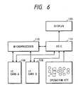
- Fig. 6 shows the functional arrangement of the electronic wallet based on this invention.
- reference numeral 115 denotes a microprocessor for the control of electronic money
- 106 is the display window
- 116 is an special-purpose integrated circuit. The functions of these devices will be explained later.
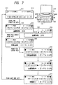
- the transfer of electronic money between two IC cards based on the foregoing electronic wallet can be practiced for the borrowing and lending of money between the husband and wife or between the parent and child in a family and between individuals. It is also possible for the user of the electronic wallet to transact electronic money with other electronic wallet or a terminal of a bank through the telephone line.
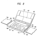
- Fig. 8 shows another external structure of an electronic wallet which incorporates the reader/writer for electronic money storing devices based on this invention.
- the electronic wallet has Power key 108 located at the top-left corner of the top, Function key 109, a large display window 106' located at the center of the top, and Transfer key 110, Cancel key 113 and Enter key 112 located at the right end of the top.
- the display window 106' displays money data for the IC cards 10A and 10B and also functions as a touch-panel for Money kind keys.
- the adoption of a touch-panel enables the switching among units of money (e.g., Japanese ⁇ and U.S. $) for Money kind keys, the entry of an amount of money with a simulated ten-key set, and the entry of an amount of money by hand writing depending on electronic money stored in each IC card and the preference of each user.
- the electronic wallets based on the foregoing embodiments of this invention allow users to conduct transactions of electronic money between IC cards by using Money kind keys (Money selecting keys) while having a feel of handling actual money.
- the keytops of Money kind keys having different shapes and sizes allows users who are not familiar with electronic appliances to enter amounts of money transfer easily and surely.
- the keytops of Money kind keys having different shapes and sizes allows weak-sighted users to identify individual Money kind keys by touching and enter amounts of money transfer easily and surely.
- the card-based electronic wallets based on the foregoing embodiments of this invention has the card holders which allow easy insertion and ejection of IC cards and the well-organized layout of the keys.
- the electronic wallet based on this invention can be designed to have the keytops of Money kind keys illuminated in different colors so that the balance of electronic money in IC cards can be read out in terms of colors (e.g., highlighted keytops of the ⁇ 10000 key and ⁇ 5000 key indicate stored electronic money of ⁇ 15000).
- the personal computer 32 which is used to transfer electronic money between IC cards linked through the telephone line, to display such keytops of Money kind keys as explained above on its display screen, with these keys being operated with a mouse device or keyboard, or to have such a touch-panel as explained above, thereby allowing users to enter amounts of money transfer easily.
- the entry of an amount of money to be transferred is based on Money kind keys, allowing users who are not familiar with electronic appliances to enter amounts of money transfer easily and surely while having a feel of handling actual money.
Landscapes
- Physics & Mathematics (AREA)
- General Physics & Mathematics (AREA)
- Financial Or Insurance-Related Operations Such As Payment And Settlement (AREA)
- Control Of Vending Devices And Auxiliary Devices For Vending Devices (AREA)
Applications Claiming Priority (2)
| Application Number | Priority Date | Filing Date | Title |
|---|---|---|---|
| JP4246296A JPH09237296A (ja) | 1996-02-29 | 1996-02-29 | 電子通貨用のリ−ダ/ライタおよび電子通貨用のリ−ダ/ライタの操作方法 |
| JP42462/96 | 1996-02-29 |
Publications (1)
| Publication Number | Publication Date |
|---|---|
| EP0793204A2 true EP0793204A2 (de) | 1997-09-03 |
Family
ID=12636748
Family Applications (1)
| Application Number | Title | Priority Date | Filing Date |
|---|---|---|---|
| EP97103119A Withdrawn EP0793204A2 (de) | 1996-02-29 | 1997-02-26 | Lese-/Schreibeinrichtung für Speichereinrichtungen für elektronisches Geld und ihr Betriebsverfahren |
Country Status (2)
| Country | Link |
|---|---|
| EP (1) | EP0793204A2 (de) |
| JP (1) | JPH09237296A (de) |
Cited By (8)
| Publication number | Priority date | Publication date | Assignee | Title |
|---|---|---|---|---|
| GB2356964A (en) * | 1999-12-03 | 2001-06-06 | Ncr Int Inc | Self-service terminal for local dispensing |
| US6622015B1 (en) | 1999-01-29 | 2003-09-16 | International Business Machines | Method and apparatus for using electronic documents within a smart phone |
| US6814285B1 (en) * | 2001-07-13 | 2004-11-09 | Chip B. Stroup | Credit information storage and transferring device |
| US7089194B1 (en) | 1999-06-17 | 2006-08-08 | International Business Machines Corporation | Method and apparatus for providing reduced cost online service and adaptive targeting of advertisements |
| EP1708147A1 (de) * | 2005-04-01 | 2006-10-04 | Conserve Italia Soc. Coop. A.R.L. | Verbessertes Zahlungssystem mit elektronischem Schlüssel für Ausgabevorrichtungen für Nahrungsmittel und/oder Getränke |
| US7229007B1 (en) | 1999-12-03 | 2007-06-12 | Ncr Corporation | Self-service terminal |
| US10089619B1 (en) * | 2017-10-04 | 2018-10-02 | Capital One Services, Llc | Electronic wallet device |
| US10592896B2 (en) | 2017-10-04 | 2020-03-17 | Capital One Services, Llc | Smart transaction card that facilitates use of transaction tokens of transaction cards |
Families Citing this family (2)
| Publication number | Priority date | Publication date | Assignee | Title |
|---|---|---|---|---|
| JP5202276B2 (ja) * | 2008-12-17 | 2013-06-05 | パナソニック株式会社 | カード装着装置 |
| JP6934498B2 (ja) * | 2019-09-04 | 2021-09-15 | 三井住友カード株式会社 | 資金移動システムおよび資金移動方法 |
-
1996
- 1996-02-29 JP JP4246296A patent/JPH09237296A/ja active Pending
-
1997
- 1997-02-26 EP EP97103119A patent/EP0793204A2/de not_active Withdrawn
Cited By (8)
| Publication number | Priority date | Publication date | Assignee | Title |
|---|---|---|---|---|
| US6622015B1 (en) | 1999-01-29 | 2003-09-16 | International Business Machines | Method and apparatus for using electronic documents within a smart phone |
| US7089194B1 (en) | 1999-06-17 | 2006-08-08 | International Business Machines Corporation | Method and apparatus for providing reduced cost online service and adaptive targeting of advertisements |
| GB2356964A (en) * | 1999-12-03 | 2001-06-06 | Ncr Int Inc | Self-service terminal for local dispensing |
| US7229007B1 (en) | 1999-12-03 | 2007-06-12 | Ncr Corporation | Self-service terminal |
| US6814285B1 (en) * | 2001-07-13 | 2004-11-09 | Chip B. Stroup | Credit information storage and transferring device |
| EP1708147A1 (de) * | 2005-04-01 | 2006-10-04 | Conserve Italia Soc. Coop. A.R.L. | Verbessertes Zahlungssystem mit elektronischem Schlüssel für Ausgabevorrichtungen für Nahrungsmittel und/oder Getränke |
| US10089619B1 (en) * | 2017-10-04 | 2018-10-02 | Capital One Services, Llc | Electronic wallet device |
| US10592896B2 (en) | 2017-10-04 | 2020-03-17 | Capital One Services, Llc | Smart transaction card that facilitates use of transaction tokens of transaction cards |
Also Published As
| Publication number | Publication date |
|---|---|
| JPH09237296A (ja) | 1997-09-09 |
Similar Documents
| Publication | Publication Date | Title |
|---|---|---|
| CA2192017C (en) | Ic card reader/writer and method of operation thereof | |
| US5936220A (en) | Electronic wallet and method of operation of the same | |
| US5945652A (en) | Electronic wallet and method for operating the same | |
| US6339638B1 (en) | Telephone used for electronic money card transaction and method of operation of the same | |
| EP0793204A2 (de) | Lese-/Schreibeinrichtung für Speichereinrichtungen für elektronisches Geld und ihr Betriebsverfahren | |
| EP0793206A2 (de) | Lese-/Schreibeinrichtung für Chipkarten und ihr Betriebsverfahren | |
| JPH09237300A (ja) | 電子財布 | |
| JP3580974B2 (ja) | 電子財布及びその操作方法 | |
| GB2346245A (en) | Electronic wallet with a plurality of card slots | |
| JPH09218928A (ja) | Icカードリーダ/ライタ及びその操作方法 | |
| JPH09114892A (ja) | 決済装置および決済システム | |
| JP2003132400A (ja) | プリペイドシステム | |
| GB2319104A (en) | IC card reader/writer | |
| JPWO1998015929A1 (ja) | Icカード読み取り書き込み機 | |
| JPH10134255A (ja) | 電子貨幣用支払い処理装置および電子貨幣用支払い処理方法 | |
| JP2003044936A (ja) | コイン型ic記憶媒体を用いる代金支払装置 | |
| JP3723953B2 (ja) | 自動取引装置 | |
| JP5098100B2 (ja) | 自動販売機、電子マネーシステム、及び自動販売機の決済方法 | |
| JPH097035A (ja) | 現金自動支払いシステム | |
| JPH09307660A (ja) | Icカードリーダ/ライタ及びその操作方法 | |
| JP2002215305A (ja) | 入力装置 | |
| KR100355243B1 (ko) | 신용거래시 비밀번호에 의한 부정거래 식별방법 | |
| JP2001060280A (ja) | 硬貨両替カード発行装置 | |
| JPH1186090A (ja) | 自動取引装置 | |
| CA2191905A1 (en) | Reader/writer for electronic money card for use in personal computer and personal computer including the same |
Legal Events
| Date | Code | Title | Description |
|---|---|---|---|
| PUAI | Public reference made under article 153(3) epc to a published international application that has entered the european phase |
Free format text: ORIGINAL CODE: 0009012 |
|
| AK | Designated contracting states |
Kind code of ref document: A2 Designated state(s): DE FR GB |
|
| STAA | Information on the status of an ep patent application or granted ep patent |
Free format text: STATUS: THE APPLICATION IS DEEMED TO BE WITHDRAWN |
|
| 18D | Application deemed to be withdrawn |
Effective date: 20000901 |