EP0793733B1 - Verfahren zur Herstellung von Zylinderteil und Nickelbasisauftragslegierungen - Google Patents
Verfahren zur Herstellung von Zylinderteil und Nickelbasisauftragslegierungen Download PDFInfo
- Publication number
- EP0793733B1 EP0793733B1 EP95940978A EP95940978A EP0793733B1 EP 0793733 B1 EP0793733 B1 EP 0793733B1 EP 95940978 A EP95940978 A EP 95940978A EP 95940978 A EP95940978 A EP 95940978A EP 0793733 B1 EP0793733 B1 EP 0793733B1
- Authority
- EP
- European Patent Office
- Prior art keywords
- alloy
- maximum
- facing
- temperature
- precipitation hardening
- Prior art date
- Legal status (The legal status is an assumption and is not a legal conclusion. Google has not performed a legal analysis and makes no representation as to the accuracy of the status listed.)
- Expired - Lifetime
Links
Images


Classifications
-
- C—CHEMISTRY; METALLURGY
- C21—METALLURGY OF IRON
- C21D—MODIFYING THE PHYSICAL STRUCTURE OF FERROUS METALS; GENERAL DEVICES FOR HEAT TREATMENT OF FERROUS OR NON-FERROUS METALS OR ALLOYS; MAKING METAL MALLEABLE, e.g. BY DECARBURISATION OR TEMPERING
- C21D6/00—Heat treatment of ferrous alloys
- C21D6/02—Hardening by precipitation
-
- B—PERFORMING OPERATIONS; TRANSPORTING
- B23—MACHINE TOOLS; METAL-WORKING NOT OTHERWISE PROVIDED FOR
- B23K—SOLDERING OR UNSOLDERING; WELDING; CLADDING OR PLATING BY SOLDERING OR WELDING; CUTTING BY APPLYING HEAT LOCALLY, e.g. FLAME CUTTING; WORKING BY LASER BEAM
- B23K35/00—Rods, electrodes, materials, or media, for use in soldering, welding, or cutting
- B23K35/22—Rods, electrodes, materials, or media, for use in soldering, welding, or cutting characterised by the composition or nature of the material
- B23K35/24—Selection of soldering or welding materials proper
- B23K35/30—Selection of soldering or welding materials proper with the principal constituent melting at less than 1550°C
- B23K35/3033—Ni as the principal constituent
- B23K35/304—Ni as the principal constituent with Cr as the next major constituent
-
- C—CHEMISTRY; METALLURGY
- C21—METALLURGY OF IRON
- C21D—MODIFYING THE PHYSICAL STRUCTURE OF FERROUS METALS; GENERAL DEVICES FOR HEAT TREATMENT OF FERROUS OR NON-FERROUS METALS OR ALLOYS; MAKING METAL MALLEABLE, e.g. BY DECARBURISATION OR TEMPERING
- C21D2251/00—Treating composite or clad material
- C21D2251/04—Welded or brazed overlays
-
- F—MECHANICAL ENGINEERING; LIGHTING; HEATING; WEAPONS; BLASTING
- F05—INDEXING SCHEMES RELATING TO ENGINES OR PUMPS IN VARIOUS SUBCLASSES OF CLASSES F01-F04
- F05C—INDEXING SCHEME RELATING TO MATERIALS, MATERIAL PROPERTIES OR MATERIAL CHARACTERISTICS FOR MACHINES, ENGINES OR PUMPS OTHER THAN NON-POSITIVE-DISPLACEMENT MACHINES OR ENGINES
- F05C2201/00—Metals
- F05C2201/02—Light metals
- F05C2201/021—Aluminium
Definitions
- the invention relates to a method of manufacturing a cylinder member, such as a valve, a seat portion, a piston or a cylinder liner, in an internal combustion engine, particularly a large two-stroke crosshead engine, which member is provided with a welded high-temperature corrosion-resistant facing alloy, the hardness of said facing alloy being increased by means of a precipitation hardening mechanism, and relates to a nickel-based facing alloy which may, for example, be welded on to such a cylinder member.
- a cylinder member such as a valve, a seat portion, a piston or a cylinder liner
- WO92/13179 describes, for example, the use of the nickel-based alloy, Alloy 50, the cobalt-based alloy, Stellite 6, and a nickel-based alloy, the most important alloy components of which are 20-24% Cr, 0.2-0.55% C and 4-7% Al.
- EP-A-0 521 821 describes a valve made of Nimonic provided with a welded layer of Inconel 625, or provided in a manner not further explained with a layer of Inconel 671 which, apart from unavoidable impurities, consists of 0.04-0.05% C, 47-49% Cr, 0.3-0.40% Ti and the balance Ni. It is mentioned that the alloy Inconel 671 does not provide a corrosion resistance as good as that of Inconel 625, which contains among other things 20-22% Cr, 8.0-9.5% Mo, 3.15-4.15% Nb+Ta and the balance Ni.
- DT-OS 24 46 517 describes a facing alloy for nuclear reactors, attempting to avoid intercrystalline corrosion by means of a welding alloy consisting of maximum 0.05% C, 1.0-5.0% Si, maximum 1.0% Mn, 20-50% Cr, 0.5-3.0% B, maximum 3.0% Cu, maximum 5.0% Fe and the balance Ni, where % Cr ⁇ 10 x % B + 13. Concrete examples mention alloys with a B content ranging from 1.13 to 2.86%.
- DE-A-2705344 describes a method of making a cylinder member in which a facing alloy is welded onto the member and then treated at a temperature higher than the operating temperature of the alloy.
- SE-B-422 338 describes a valve for an internal combustion engine having a basic body of a chromium-containing nickel alloy which is coated with a chromium-containing cobalt alloy at a temperature exceeding 3000°C, whereupon the member is subjected to mechanical machining and ageing at a temperature higher than the working temperature, the aim of which is to stabilize the structure and dimensions of the alloy and counteract intercrystalline corrosion.
- DK-B-165125 describes an exhaust valve for an internal combustion engine with a high-temperature corrosion-resistant facing alloy comprising 13-17% Cr, 2-6% Al, 0.1-8% Mo, 1.5-3.5% B, 0.5-3% Ti, 4-7% Co and the balance Ni.
- the purpose of the known facings on valves is, among other things, to provide a surface on the member with excellent high-temperature corrosion resistance so that the material is not corroded by the highly corroding environment in a heavy fuel oil diesel engine, and in case of seat areas, a surface of high hardness so that the formation of dent marks is counteracted, and at the same time the material deposited should have a high ductility counteracting the formation of cold cracks in the material.
- the hardness of the facing has mainly been provided by precipitation of carbide networks, borides and/or intermetals, such as Ni 3 Al ( ⁇ '), ⁇ -phase, ⁇ -phase or Laves-phase in the basic matrix of the alloy, and by solution hardening.
- the known welded facing alloys are very exposed to cold cracking in the welding material at the cooling of the member following welding, viz. cracks present immediately following the conclusion of welding.
- the cold cracks require either rejection or repair of the members with the welded facing.
- the problem of cold cracking is particularly pronounced in the known boron-containing facing alloys, because these known alloys have very low ductility.
- B is here used for precipitation of borides to increase the hardness and abrasion resistance of the alloy.
- the alloy comprises a nickel-rich ⁇ -phase and a chromium-rich ⁇ -phase where both phases, depending on the precise analysis of the alloy, may constitute the primary dendrite structure.
- EP-A-0529208 describes a chromium-based hardfacing alloy for welding in the valve seat area on the valves in a car engine.
- the alloy contains 30-48% Ni, 1.5-15% W and/or 1.0-6.5% Mo, and the balance is of at least 40% Cr.
- the welding is performed by means of laser welding, and at the cooling of the solidified chromium-containing ⁇ -phase, a nickel-containing phase is precipitated.
- W and Mo have a solution enhancing effect on the alloy and contribute vitally to its strength.
- C can be added in amounts of 0.3-2.0% to increase the hardness by formation of carbides, and B can be added in amounts of 0.1-1.5% to increase the hardness by formation of chromium borides.
- Nb can be added in amounts of 1.0-4.0% to form hardness-increasing intermetallic compounds as well as carbides and borides.
- the hardness of the alloy is thus created immediately upon welding by precipitation of carbide networks, borides and/or intermetals in the chromium-containing basic matrix of the alloy and by solution hardening like in the above alloys. Consequently, great care and special welding methods must be applied, such as laser welding, to avoid cracking in immediate connection with the welding process.
- the object of the invention is to provide a method of manufacturing a cylinder member and a facing alloy which have a high resistance to hot corrosion in the environment existing in the working chamber of an internal combustion engine, while at the same time the risk of cracking in connection with welding is substantially lower than in the known alloys so that welding methods with a suitably high melting rate can be used to weld the alloy on to large members on a commercial basis.
- the method of manufacturing cylinder member according to the invention is defined in claim 1 and the facing alloy is defined in claim 5.
- the precipitation hardening mechanism in the welded facing alloy is based on a solid-state phase transformation, that the temperature of activating the precipitation hardening mechanism is above the operating temperature of the alloy, and the precipitation hardening mechanism acts so slowly that the alloy substantially does not harden at welding on the cylinder member, but hardens during a subsequent heat treatment at a temperature higher than the activation temperature for the precipitation hardening mechanism.
- the desired hardness has been achieved with a substantially smaller precipitation of eutectics and hard phases during solidification than in the known alloys. This strengthens the mutual bonds between the primary dendritic precipitates, which counteracts hot cracking.
- the slow-acting hardening mechanism only increases the hardness of the alloy at the subsequent heat treatment after the alloy has been stress-relieved, as will be explained in detail below.
- the welded facing alloy retains a high ductility of, for example, 25%, which prevents the residual stresses after welding corresponding to the yield stress of the alloy from generating cracks.
- the yield stress of facing alloys of the type mentioned here increases with the increasing hardness of the alloy, just as the temperature for achieving stress relieving also increases.
- the welded, still very ductile alloy becomes exposed to a temperature level which releases the residual stresses by means of stress relieving.
- the low hardness of the alloy before hardening causes the stresses to be relieved quickly and at a low temperature.
- the composition of the alloy must be chosen so that in the area around the chosen analysis, the main elements of the alloy depicted in a phase diagram exhibit an oblique dividing line for the state of equilibrium between two different phase areas, where, for example, one phase area may contain the crystal lattice form, BCC (Body Centered Cubic), and the other a mixture of BCC and the so-called FFC form (Face Centred Cubic).
- BCC Crystal lattice form
- FFC form Feace Centred Cubic
- the alloy does not have time to adjust itself to the state of equilibrium, i.e., judged in relation to the state of equilibrium the alloy will have too large a proportion of one phase.
- the underrepresented phase will be point) precipitated in the overrepresented phase, which generates internal stresses with crystal distortions preventing dislocations from travelling through the crystal grains, whereby the alloy achieves high hardness.
- the transformation from one to the other phase takes place through diffusion of the alloy components, and extremely small point precipitates occur which are so finely distributed that the resulting alloy has a very uniform microhardness.
- Such solid-state phase transformations are in themselves known from other alloys, but the feature of importance to the invention is that for the chosen analysis of the facing alloy, the transformation takes so long that it does not become active in the period passing until the just welded material has cooled below the hardening temperature. As the welded material retains high ductility until hardening, the cylinder member may without problems be exposed to mechanical machining to the finished geometry, whereupon hardening is performed.
- the cylinder member is preferably provided with a facing alloy which solidifies on welding primarily in an austenitic phase, part of which becomes transformed into a ferritic phase at temperatures above the activation temperature for the precipitation hardening mechanism.
- This precipitation of the ferritic BCC form in the austenitic FCC form is advantageous for achieving high hardness and is extremely suitable in connection with facing alloys which normally contain nickel and chromium, as the binary Cr-Ni phase diagram has a characteristic, slightly S-shaped dividing line between the austenitic nickel-rich phase and the more chromium-rich phase area.
- the activation temperature for precipitation hardening of the alloy may suitably be in the interval from 550 to 1100°C, preferably from 700 to 850°C, and at the same time activation of the precipitation hardening mechanism requires said activation temperature to be exceeded for more than 40 s, suitably for more than 20 min.
- the facing alloy of the cylinder member is especially adapted to the welding methods which have a melting rate advantageously high for the manufacture of the members, and to the operating temperatures occurring in cylinder members in a large two-stroke crosshead engine. If the cylinder members are to be used in smaller engines, other temperature levels may be chosen.
- the facing alloy of claim 5 comprises from 40 to 51% Cr, from 0 to 0.1% C, less than 1.0% Si, from 0 to 5.0% Mn, less than 1.0% Mo, from 0.05 to less than 0.5% B, from 0 to 1.0% Al, from 0 to 1.5% Ti, from 0 to 0.2% Zr, from 0.5 to 3.0% Nb, an aggregate content of Co and Fe of maximum 5.0%, maximum 0.2% O, maximum 0.3% N and the balance Ni.
- the large content of Cr promotes the corrosion properties of the nickel alloy in the relevant operating environment.
- the welded alloy has better corrosion properties and higher hardness at the operating temperatures from 500 to 700°C than the known hardfacings on cylinder members, and better mechanical properties than the above cast nickel alloys.
- the solid phase transformation cannot be achieved in a suitable manner, as the activation temperature becomes too low when the lower Cr interval limit is not reached, and if the upper Cr interval limit is exceeded, the solidification interval of the alloy is increased, and primarily ferrite may be precipitated in a hard and brittle phase resulting in an undesired fall in ductility.
- the amounts of the other alloy components determine the precise positioning of the dividing line in the phase diagram between the two relevant phases, which means that the optimum content of Cr can be adjusted finely by tests to achieve the desired activation temperature for the hardening when the other alloy components are known.
- the content of B has surprisingly turned out to be decisive for the weldability of the nickel alloy with the high Cr content.
- B causes the solidification of the melt to change from cellular solidification into dendritic solidification, where the dendritic branches interlock and produce a geometrical locking of the structural components so as to avoid more extended and plane film layers in the 5 melt which is the last to solidify.
- the content of B contributes substantially to the high resistance of the alloy to hot cracking at welding.
- B is largely insoluble in the ⁇ and ⁇ -phases, and it is presumed that the solidification involves a eutectic with a number of borides.
- Nb influences the solid phase transformation to provide globular precipitation rather than lamellar precipitation, which increases the ductility of the alloy remaining after heat treatment. This is of importance particularly to cylinder members which are exposed to mechanical influences during operation. A corresponding effect can be achieved with Ta, Ti and Zr, but Ta is very expensive, and more than 1.5% Ti may cause intermetallic precipitation making the alloy harden partially and embrittle at the welding, and a content of Zr exceeding 0.2% may cause hot cracking at welding.
- a content of Mo of less than 1.0% may contribute to strengthen the austenitic phase through a solutionenhancing effect which gives the alloy greater tensile strength.
- Si, Mn and Al have a de-oxidizing effect at welding and are therefore, to avoid welding defects, desirable as components in the filler material used at welding. Although some of the de-oxidising agent is burned away at welding, part of it will remain in the finished alloy. It is desired to limit Si to less than 1%, as Si reduces the desired effect of B and necessitates a larger addition thereof. Mn is not quite such an efficient de-oxidizing agent, and it is desired to limit the amount to maximum 5% so as not to dilute the active components in the finished alloy. An Al content of more than 1% may cause undesired precipitation of the intermetallic phase Ni 3 Al, which increases the hardness of the nickel matrix already during the welding process.
- C is a common impurity in commercial alloys, and it is expensive to remove C completely.
- the C content should be limited to maximum 0.1% to avoid or reduce carbide formations.
- O and N will normally be deposited in the alloy from the ambient air, but they do not contribute to the desired properties.
- Co and Fe are also impurities which it is desired to limit to an aggregate content of maximum 5%.
- the invention also relates to a nickel-based facing alloy which is characterized according to the invention in that expressed in percentage by weight and apart from commonly occurring impurities, it comprises from 40 to 51% Cr, from 0 to 0.1% C, less than 1.0% Si, from 0 to 5.0% Mn, less than 1.0% Mo, from 0.05 to less than 0.5% B, from 0 to 1.0% Al, from 0 to 1.5% Ti, from 0 to 0.2% Zr, from 0.5 to 3.0% Nb, an aggregate content of Co and Fe of maximum 5.0%, maximum 0.2% O, maximum 0.3% N and the balance Ni.
- this alloy is distinguished by very good high-temperature corrosion resistance and by being weldable largely without any risk of cracking and by being heat-treatable to high hardness at temperatures of, for example, 650-800°C with retention of a ductility which permits the use of the alloy on mechanically loaded members as a protective facing and/or a hard facing.
- the influence of the individual components on the properties of the alloy are mentioned above.
- the content of Al is maximum 0.1%
- the content of Ti is preferably maximum 0.1%.
- Such low contents of Al and Ti suppress precipitation during welding of the hardness-increasing and thus ductility-lowering intermetallic phase Ni 3 Al(Ti).
- the Cr content of the alloy may suitably be in the interval from 45 to 50%.
- a Cr content of minimum 45% provides the advantage that the precipitation hardening mechanism takes place in a more controlled manner and at a higher activation temperature, which means partly that the alloy at welding is cooled quickly below the activation temperature, partly that the subsequent machining of the member to the final geometry can take place largely without taking into consideration the heating of the member by the machining.
- the upper limit of 50% provides suitable certainty against formation of the hard and brittle primary ferrite phase.
- the alloy contains from 0.15 to 0.40% B, preferably maximum 0.25% B.
- the upper limit of 0.4% B provides suitable certainty that hardness-increasing borides are not precipitated in too large amounts when the alloy solidifies, and the lower limit of 0.15% ensures that at the dilution of the welding metal with the basic material of the member, the boron content does not in local areas become so low that hot cracks can easily arise.
- the ability of boron to produce the desired dendritic structure in the alloy is reduced at a falling Cr content in the alloy. At a Cr content of less than 45%, the content of B is therefore preferably from 0.20 to 0.30%.
- the preferred upper limit of 0.25% is suitable in alloys with at least 45% Cr.
- the content of Si in the welded alloy is preferably maximum 0.03%, and because, as mentioned, the content of Mn has a diluting effect, the Mn content may suitably be restricted to maximum 0.5%. For the same reason a content of Mo of maximum 0.5% is preferred, and/or an aggregate content of Co and Fe of maximum 1.0% and maximum 0.02% O and maximum 0.02% N.
- the advantageous change in the hardening mechanism to take place with globular precipitation is strengthened if the content of Nb is at minimum 1.0%, and for economic reasons the content of the relatively costly Nb may suitably be limited to 2.0%, as a higher content of Nb usually does not substantially improve the properties of the alloy.
- the risk of hot cracks at welding may suitably be limited by incorporating maximum 0.02% Zr in the alloy.
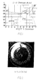
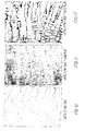
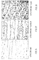
- the binary phase diagram shown in Fig. 1 shows the slightly S-shaped dividing line between the equilibrium phases ⁇ and ⁇ - ⁇ .
- the dividing line starts at a temperature of about 1345°C from a point at about 47% Cr and extends obliquely downwards to a point at about 38% Cr at a temperature of 500°C.
- Ni-Cr alloy in the above area is welded, the solidification of the weld pool and the subsequent cooling will take place so rapidly that mainly austenitic nickel phase ⁇ is formed.
- the ferritic ⁇ -phase will be precipitated in the nickel phase as very finely distributed globular precipitates.
- the exact position of the dividing line depends on the type and amount of all alloy components.
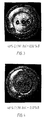
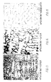
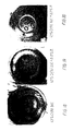
- Nickel alloys with a high content of Cr have so far been considered very difficult to weld owing to the high risk of hot cracking, which was confirmed at the two reference tests.
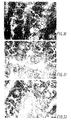
- Figs. 2 and 11 the well-known strong cracking due to hot cracking is seen.
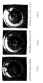
- Figs. 10 and 24 show that solidification has taken place cellularly with the dark extended plane film layers between the crystal grains.
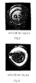
- Figs. 7-9 and 15-17 show alloys with an addition of Si in amounts of 0.09%, 0.17%,and 0.33%, respectively, and with an associated content of B of 0.06%, 0.11% and 0.21%, respectively. It can be seen that Si reduces the ability of B to produce a dendritic solidification structure.
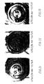
- An alloy according to the invention was prepared, having the following analysis: 48.6% Cr, 1.5% Nb, 0.67% Mn, 0.39% Si, 0.1% B, 0.012% C and the balance Ni.
- the alloy was welded on to a member in the same manner as mentioned above, only two weld beads were applied on top of each other. No cracking could be observed after the welding. After welding, the hardness of the alloy at 20°C was measured to 200 HV20. The member was then heat-treated for 72 hours at a temperature of 700°C. After the heat treatment no cracking could be observed either.
- the hardness of the alloy was measured to 511 HV20 and 460 HBW at 20°C and 415 HBW at 500°C, which shows that the alloy retains an extremely advantageous, high hardness at a high temperature.
- the sample was cut, ground and polished in the usual manner.
- Fig. 30 shows a photo of the alloy, and it can be seen immediately that the structure of the hardened alloy is so fine that the individual structural components can hardly be distinguished despite the powerful magnification.
- the alloy can be welded on as a corrosion protective facing on the surfaces that come into contact with the environment in the internal combustion chamber of an engine. Furthermore, the high-temperature hardness is so high that the alloys according to the invention are very suitable as welded hardfacing alloys for valve seat areas.
Landscapes
- Chemical & Material Sciences (AREA)
- Engineering & Computer Science (AREA)
- Mechanical Engineering (AREA)
- Physics & Mathematics (AREA)
- Thermal Sciences (AREA)
- Crystallography & Structural Chemistry (AREA)
- Materials Engineering (AREA)
- Metallurgy (AREA)
- Organic Chemistry (AREA)
- Chemically Coating (AREA)
- Pens And Brushes (AREA)
- Heat Treatment Of Articles (AREA)
- Materials For Medical Uses (AREA)
- Laminated Bodies (AREA)
- Arc Welding In General (AREA)
- Pistons, Piston Rings, And Cylinders (AREA)
- Forging (AREA)
- Diaphragms For Electromechanical Transducers (AREA)
- Laser Beam Processing (AREA)
- Cylinder Crankcases Of Internal Combustion Engines (AREA)
- Coating By Spraying Or Casting (AREA)
Claims (13)
- Verfahren zur Herstellung eines Zylinderteils, wie eines Ventils, eines Ventilsitzbereichs, eines Kolbens oder einer Zylinderbüchse, für eine Brennkraftmaschine, insbesondere eine Zweitakt-Kreuzkopf-Großbrennkraftmaschine, bei dem eine hochtemperaturkorrosionsbeständige Auftragslegierung auf das Teil aufgeschweißt wird und bei dem die Härte der Auftragslegierung mittels eines Präzipitationshärtungsmechanismus erhöht wird, dadurch gekennzeichnet, daß der Präzipitationshärtungsmechanismus in der geschweißten Auftragslegierung auf einer Festphasentransformation beruht, daß der Präzipitationshärtungsmechanismus so langsam wirkt, daß die Legierung im wesentlichen nicht beim Schweißen auf dem Zylinderteil härtet, daß die geschweißte Auftragslegierung spannungsfreigeglüht wird, bevor der Präzipitationshärtungsmechanismus bei einer Temperatur oberhalb der Betriebstemperatur der Legierung aktiviert wird, und daß die Auftragslegierung anschließend unter einer Wärmebehandlung bei einer Temperatur, die höher ist als die Aktivierungstemperatur für den Präzipitationshärtungsmechanismus, gehärtet wird.
- Verfahren nach Anspruch 1, dadurch gekennzeichnet, daß die Auftragslegierung beim Schweißen primär in einer austenitischen Phase (γ) sich verfestigt, von der ein Teil in eine ferritische Phase (α) bei Temperaturen transformiert wird, die oberhalb der Aktivierungstemperatur für den Präzipitationshärtungsmechanismus liegt.
- Verfahren nach Anspruch 1 oder 2, dadurch gekennzeichnet, daß die Aktivierungstemperatur für das Präzipitationshärten der Legierung im Intervall von 550 bis 1100°C, vorzugsweise von 700 bis 850°C liegt, und daß die Aktivierung des Präzipitationshärtungsmechanismus erfordert, daß die Aktivierunstemperatur um mehr als 40s, geeigneterweise mehr als 20 min überschritten wird.
- Verfahren nach einem der Ansprüche 1 bis 3, gekennzeichnet durch das Verwenden einer Legierung, welche, in Gew.-% ausgedrückt und abgesehen von üblicherweise auftretenden Verunreinigungen, 40 bis 51% Cr, 0 bis 0,1% C, weniger als 1,0% Si, 0 bis 5,0% Mn, weniger als 1,0% Mo, 0,05 bis weniger als 0,5% B, 0 bis 1,0% Al, 0 bis 1,5% Ti, 0 bis 0,2% Zr, 0,5 bis 3,0% Nb, einen Aggregatgehalt an Co und Fe von maximal 5,0%, maximal 0,2% O, maximal o,3% N, Rest Ni umfaßt, als Auftragslegierung für das Zylinderteil.
- Auftragslegierung auf der Basis von Nickel, gekennzeichnet durch, in Gew.-% ausgedrückt und abgesehen von üblicherweise auftretenden Verunreinigungen, 40 bis 51% Cr, 0 bis 0,1% C, weniger als 1,0% Si, 0 bis 5,0% Mn, weniger als 1,0% Mo, 0,05 bis weniger als 0,5% B, 0 bis 1,0% Al, 0 bis 1,5% Ti, 0 bis 0,2% Zr, 0,5 bis 3,0% Nb, einen Aggregatgehalt an Co und Fe von maximal 5,0%, maximal 0,2% O, maximal o,3% N, Rest Ni.
- Auftragslegierung nach Anspruch 5, gekennzeichnet durch einen Gehalt an Al von maximal 0,1% und einen Gehalt an Ti von maximal 0,1%.
- Auftragslegierung nach Anspruch 5 oder 6, dadurch gekennzeichnet, daß die Legierung 45 bis 50% Cr enthält.
- Auftragslegierung nach einem der Ansprüche 5 bis 7, dadurch gekennzeichnet, daß die Legierung 0,15 bis 0,40% B, vorzugsweise maximal 0,25% B enthält.
- Auftragslegierung nach einem der Ansprüche 5 bis 8, dadurch gekennzeichnet, daß die Legierung maximal 0,03% Si und vorzugsweise maximal 0,5% Mn enthält.
- Auftragslegierung nach einem der Ansprüche 5 bis 9, dadurch gekennzeichnet, daß die Legierung maximal 0,5% Mo enthält.
- Auftragslegierung nach einem der Ansprüche 5 bis 10, dadurch gekennzeichnet, daß die Legierung 1,0 bis 2,0% Nb und vorzugsweise maximal 0,02% Zr enthält.
- Auftragslegierung nach einem der Ansprüche 5 bis 11, dadurch gekennzeichnet, daß der Aggregatgehalt an Co und Fe der Legierung maximal 1,0% ist und daß die Legierung geeigneterweise maximal 0,02% O und 0,02 N enthält.
- Auftragslegierung nach einem der Ansprüche 5 bis 12, dadurch gekennzeichnet, daß sie zum Schweißen auf einem Zylinderteil, wie einem Auslaßventil, in einer Zweitakt-Großbrennkraftmaschine, insbesondere einer Vortriebsmaschine in einem Schiff oder einer stationären Stromerzeugungsmaschine verwendet wird.
Applications Claiming Priority (4)
| Application Number | Priority Date | Filing Date | Title |
|---|---|---|---|
| DK1428/94 | 1994-12-13 | ||
| DK199401428A DK172987B1 (da) | 1994-12-13 | 1994-12-13 | Cylinderelement, nikkelbaseret pålægningslegering og anvendelse af legeringen |
| DK142894 | 1994-12-13 | ||
| PCT/DK1995/000503 WO1996018747A1 (en) | 1994-12-13 | 1995-12-12 | A cylinder member and nickel-based facing alloys |
Publications (2)
| Publication Number | Publication Date |
|---|---|
| EP0793733A1 EP0793733A1 (de) | 1997-09-10 |
| EP0793733B1 true EP0793733B1 (de) | 1999-08-25 |
Family
ID=8104733
Family Applications (1)
| Application Number | Title | Priority Date | Filing Date |
|---|---|---|---|
| EP95940978A Expired - Lifetime EP0793733B1 (de) | 1994-12-13 | 1995-12-12 | Verfahren zur Herstellung von Zylinderteil und Nickelbasisauftragslegierungen |
Country Status (14)
| Country | Link |
|---|---|
| US (1) | US5958332A (de) |
| EP (1) | EP0793733B1 (de) |
| JP (1) | JP3370338B2 (de) |
| KR (1) | KR100353193B1 (de) |
| AT (1) | ATE183780T1 (de) |
| AU (1) | AU4253896A (de) |
| DE (1) | DE69511717T2 (de) |
| DK (1) | DK172987B1 (de) |
| ES (1) | ES2136893T3 (de) |
| HR (1) | HRP950590B1 (de) |
| NO (1) | NO314667B1 (de) |
| PL (1) | PL179454B1 (de) |
| TW (1) | TW305011B (de) |
| WO (1) | WO1996018747A1 (de) |
Families Citing this family (24)
| Publication number | Priority date | Publication date | Assignee | Title |
|---|---|---|---|---|
| DK173136B1 (da) | 1996-05-15 | 2000-02-07 | Man B & W Diesel As | Bevægeligt vægelement i form af en udstødsventilspindel eller et stempel i en forbrændingsmotor. |
| US6017591A (en) * | 1996-11-14 | 2000-01-25 | Ford Global Technologies, Inc. | Method of making adherently sprayed valve seats |
| DE19826138B4 (de) * | 1998-04-17 | 2007-06-28 | NU TECH Gesellschaft für Lasertechnik Materialprüfung und Meßtechnik mbH | Verfahren zur Herstellung eines Werkstücks mit einer verschleißbeständigen Oberfläche |
| DE19959292A1 (de) * | 1999-12-09 | 2001-06-13 | Rolls Royce Deutschland | Verfahren zum Herstellen einer Brennkammer eines Gasturbinen-Triebwerks |
| CA2348145C (en) | 2001-05-22 | 2005-04-12 | Surface Engineered Products Corporation | Protective system for high temperature metal alloys |
| US6475647B1 (en) | 2000-10-18 | 2002-11-05 | Surface Engineered Products Corporation | Protective coating system for high temperature stainless steel |
| US6655369B2 (en) * | 2001-08-01 | 2003-12-02 | Diesel Engine Transformations Llc | Catalytic combustion surfaces and method for creating catalytic combustion surfaces |
| US6508240B1 (en) | 2001-09-18 | 2003-01-21 | Federal-Mogul World Wide, Inc. | Cylinder liner having EGR coating |
| WO2003057933A1 (fr) * | 2002-01-08 | 2003-07-17 | Mitsubishi Materials Corporation | Alliage a base de nickel presentant une excellente resistance a la corrosion dans un milieu aqueux supercritique contenant de l'acide inorganique |
| US6749894B2 (en) * | 2002-06-28 | 2004-06-15 | Surface Engineered Products Corporation | Corrosion-resistant coatings for steel tubes |
| US7458358B2 (en) * | 2006-05-10 | 2008-12-02 | Federal Mogul World Wide, Inc. | Thermal oxidation protective surface for steel pistons |
| US8613886B2 (en) * | 2006-06-29 | 2013-12-24 | L. E. Jones Company | Nickel-rich wear resistant alloy and method of making and use thereof |
| US8568901B2 (en) * | 2006-11-21 | 2013-10-29 | Huntington Alloys Corporation | Filler metal composition and method for overlaying low NOx power boiler tubes |
| US7754143B2 (en) * | 2008-04-15 | 2010-07-13 | L. E. Jones Company | Cobalt-rich wear resistant alloy and method of making and use thereof |
| US20100119872A1 (en) * | 2008-11-13 | 2010-05-13 | Lundeen Calvin D | Iron-based hard facing alloys with rare earth additions |
| EP2366674A4 (de) * | 2008-12-16 | 2013-08-14 | Asahi Glass Co Ltd | Mit einem film überzogenes metallelement für eine anlage zur herstellung von floatglas und verfahren zur herstellung von floatglas |
| RU2434146C2 (ru) * | 2009-01-23 | 2011-11-20 | Ман Диесель, Филиаль Аф Ман Диесель Се, Тюскланд | Подвижный элемент стенки в форме стержня выпускного клапана или поршня для двигателя внутреннего сгорания и способ изготовления такого элемента |
| JP5036879B2 (ja) * | 2009-01-23 | 2012-09-26 | マン・ディーゼル・アンド・ターボ,フィリアル・アフ・マン・ディーゼル・アンド・ターボ・エスイー,ティスクランド | 内燃機関のための、排気弁スピンドルまたはピストンの形態にある可動壁部材、および当該部材を製造する方法 |
| DK177071B1 (en) * | 2009-10-30 | 2011-05-30 | Man Diesel & Turbo Deutschland | Exhaust valve spindle for an internal combustion engine and a method of manufacture thereof |
| KR101999569B1 (ko) * | 2011-12-08 | 2019-07-15 | 테네코 인코퍼레이티드 | 개선된 연소 보울 림 영역을 가진 원피스형 피스톤 및 그 제조 방법 |
| DK177487B1 (en) * | 2012-07-06 | 2013-07-15 | Man Diesel & Turbo Deutschland | An exhaust valve spindle for an exhaust valve in an internal combustion engine |
| JP6156316B2 (ja) * | 2014-10-09 | 2017-07-05 | トヨタ自動車株式会社 | 肉盛用合金粉末、これを用いた肉盛合金部材、およびエンジン用バルブ |
| ITUA20161551A1 (it) | 2016-03-10 | 2017-09-10 | Nuovo Pignone Tecnologie Srl | Lega avente elevata resistenza all’ossidazione ed applicazioni di turbine a gas che la impiegano |
| DE102016115026B4 (de) * | 2016-08-12 | 2018-03-08 | Vdm Metals International Gmbh | Verfahren zur Herstellung von walzplattierten Blechen sowie walzplattierte Bleche |
Family Cites Families (19)
| Publication number | Priority date | Publication date | Assignee | Title |
|---|---|---|---|---|
| DE2446517C3 (de) * | 1974-09-28 | 1979-08-30 | Vereinigte Edelstahlwerke Ag (Vew), Wien Niederlassung Vereinigte Edelstahlwerke Ag (Vew) Verkaufsniederlassung Buederich, 4005 Meerbusch | Karbidfreier Schweißzusatzwerkstoff für das Auftragschweißen |
| FR2341039A1 (fr) * | 1976-02-11 | 1977-09-09 | Dervaux Ets | Procede de fabrication d'organes mecaniques tels que des soupapes pour moteurs thermiques |
| JPS6249341B2 (de) * | 1978-03-16 | 1987-10-19 | Fukuda Metal Foil Powder | |
| DE3018007A1 (de) * | 1980-05-10 | 1981-11-12 | Metallgesellschaft Ag, 6000 Frankfurt | Pulverfoermiger zusatzverbundwerkstoff |
| KR890003345B1 (ko) * | 1984-11-26 | 1989-09-18 | 삼성전자 주식회사 | 전기 저항용 비정질 닉켈 합금 |
| DK165125C (da) * | 1985-01-31 | 1993-02-22 | Hitachi Shipbuilding Eng Co | Varmeresistent legering med hoej haardhed |
| US5556594A (en) * | 1986-05-30 | 1996-09-17 | Crs Holdings, Inc. | Corrosion resistant age hardenable nickel-base alloy |
| US4810467A (en) * | 1987-08-06 | 1989-03-07 | General Electric Company | Nickel-base alloy |
| JPS6452050A (en) * | 1987-08-19 | 1989-02-28 | Kobe Steel Ltd | Alloy powder for thermal spraying |
| US4844864A (en) * | 1988-04-27 | 1989-07-04 | Carpenter Technology Corporation | Precipitation hardenable, nickel-base alloy |
| JP2778705B2 (ja) * | 1988-09-30 | 1998-07-23 | 日立金属株式会社 | Ni基超耐熱合金およびその製造方法 |
| DE3907564A1 (de) * | 1989-03-09 | 1990-09-13 | Vdm Nickel Tech | Nickel-chrom-eisen-legierung |
| JPH03287736A (ja) * | 1990-04-04 | 1991-12-18 | Okano Valve Seizo Kk | 耐熱耐食性Cr―Ni基合金 |
| DK166219C (da) * | 1991-01-23 | 1993-08-16 | Man B & W Diesel Gmbh | Ventil med haardpaalaegning |
| DE59206839D1 (de) * | 1991-07-04 | 1996-09-05 | New Sulzer Diesel Ag | Auslassventil einer Diesel-Brennkraftmaschine und Verfahren zum Herstellen des Ventils |
| JP3148340B2 (ja) * | 1991-08-27 | 2001-03-19 | 福田金属箔粉工業株式会社 | ハードフェーシング用高靱性クロム基合金、その粉末、および該合金を肉盛した自動車用エンジンバルブ |
| US5495837A (en) * | 1993-06-11 | 1996-03-05 | Mitsubishi Materials Corporation | Engine valve having improved high-temperature wear resistance |
| US5753177A (en) * | 1994-03-10 | 1998-05-19 | Doryokuro Kakunenryo Kaihatsu Jigyodan | High-Ni austenitic stainless steel having excellent high-temperature strength |
| KR100194731B1 (ko) * | 1996-04-04 | 1999-06-15 | 류정열 | 자동차용 티타늄 배기 밸브 제조 방법 |
-
1994
- 1994-12-13 DK DK199401428A patent/DK172987B1/da not_active IP Right Cessation
-
1995
- 1995-11-23 TW TW084112476A patent/TW305011B/zh not_active IP Right Cessation
- 1995-12-11 HR HR1428/94A patent/HRP950590B1/xx not_active IP Right Cessation
- 1995-12-12 PL PL95320673A patent/PL179454B1/pl not_active IP Right Cessation
- 1995-12-12 JP JP51808996A patent/JP3370338B2/ja not_active Expired - Fee Related
- 1995-12-12 AU AU42538/96A patent/AU4253896A/en not_active Abandoned
- 1995-12-12 AT AT95940978T patent/ATE183780T1/de not_active IP Right Cessation
- 1995-12-12 ES ES95940978T patent/ES2136893T3/es not_active Expired - Lifetime
- 1995-12-12 DE DE69511717T patent/DE69511717T2/de not_active Expired - Fee Related
- 1995-12-12 KR KR1019970703944A patent/KR100353193B1/ko not_active Expired - Fee Related
- 1995-12-12 WO PCT/DK1995/000503 patent/WO1996018747A1/en not_active Ceased
- 1995-12-12 EP EP95940978A patent/EP0793733B1/de not_active Expired - Lifetime
-
1997
- 1997-06-11 NO NO19972689A patent/NO314667B1/no not_active IP Right Cessation
- 1997-06-11 US US08/873,246 patent/US5958332A/en not_active Expired - Fee Related
Also Published As
| Publication number | Publication date |
|---|---|
| WO1996018747A1 (en) | 1996-06-20 |
| US5958332A (en) | 1999-09-28 |
| DE69511717D1 (de) | 1999-09-30 |
| DK172987B1 (da) | 1999-11-01 |
| PL320673A1 (en) | 1997-10-27 |
| DE69511717T2 (de) | 2000-02-17 |
| NO972689L (no) | 1997-06-11 |
| ATE183780T1 (de) | 1999-09-15 |
| AU4253896A (en) | 1996-07-03 |
| JP3370338B2 (ja) | 2003-01-27 |
| NO314667B1 (no) | 2003-04-28 |
| KR100353193B1 (ko) | 2002-12-28 |
| TW305011B (de) | 1997-05-11 |
| HRP950590B1 (en) | 2000-02-29 |
| EP0793733A1 (de) | 1997-09-10 |
| PL179454B1 (en) | 2000-09-29 |
| JPH10510323A (ja) | 1998-10-06 |
| HRP950590A2 (en) | 1997-08-31 |
| NO972689D0 (no) | 1997-06-11 |
| ES2136893T3 (es) | 1999-12-01 |
| DK142894A (da) | 1996-06-14 |
Similar Documents
| Publication | Publication Date | Title |
|---|---|---|
| EP0793733B1 (de) | Verfahren zur Herstellung von Zylinderteil und Nickelbasisauftragslegierungen | |
| US4219592A (en) | Two-way surfacing process by fusion welding | |
| US4787736A (en) | Laser clad valve for internal combustion engine | |
| CA1295096C (en) | Hardsurfaced power-generating turbine components and method of hardsurfacing metal substrates using a buttering layer | |
| Wagner et al. | Physical metallurgy of alloy 718 | |
| RU2175722C2 (ru) | Подвижный перегородочный элемент в виде выпускного клапана или поршня в двигателе внутреннего сгорания | |
| US5431136A (en) | Internal combustion valve having an iron based hard-facing alloy contact surface | |
| EP1338663A1 (de) | Hitzebeständige, auf nickel basierende legierung und diese beinhaltende schweissverbindung | |
| US11732331B2 (en) | Ni-based alloy, and Ni-based alloy product and methods for producing the same | |
| US4213026A (en) | Age hardenable nickel superalloy welding wires containing manganese | |
| US5495837A (en) | Engine valve having improved high-temperature wear resistance | |
| CA2491754C (en) | Wear-resistant, corrosion-resistant cobalt-based alloys | |
| CN1080769C (zh) | 缸体构件及镍基表面加硬用硬合金 | |
| US5192625A (en) | Cobalt-base wrought alloy compositions and articles | |
| EP0568598B1 (de) | Ventil mit aufpanzerung | |
| GB1592407A (en) | Age hardenable nickel superalloy welding wires containing manganese | |
| Klarstrom et al. | A new gas turbine combustor alloy | |
| JP3332771B2 (ja) | ごみ焼却装置用耐食耐熱Ni基鋳造合金 | |
| KR100254939B1 (ko) | 내연기관용 엔진밸브 | |
| JPH06277876A (ja) | ディーゼル機関用弁棒とその製造方法 | |
| Kiser | Special metallurgical welding considerations for nickel and cobalt alloys and superalloys | |
| Sato et al. | Development of a Cobalt Base Superalloy for Heavy Duty Gas Turbine Nozzles | |
| Witter et al. | Cast iron-base alloy for cylinder/regenerator housing | |
| JPH0558835B2 (de) | ||
| JPS59100248A (ja) | 内燃機関のバルブおよびバルブシ−ト用Ni基合金 |
Legal Events
| Date | Code | Title | Description |
|---|---|---|---|
| PUAI | Public reference made under article 153(3) epc to a published international application that has entered the european phase |
Free format text: ORIGINAL CODE: 0009012 |
|
| 17P | Request for examination filed |
Effective date: 19970609 |
|
| AK | Designated contracting states |
Kind code of ref document: A1 Designated state(s): AT DE ES GB NL SE |
|
| 17Q | First examination report despatched |
Effective date: 19980306 |
|
| GRAG | Despatch of communication of intention to grant |
Free format text: ORIGINAL CODE: EPIDOS AGRA |
|
| GRAG | Despatch of communication of intention to grant |
Free format text: ORIGINAL CODE: EPIDOS AGRA |
|
| GRAG | Despatch of communication of intention to grant |
Free format text: ORIGINAL CODE: EPIDOS AGRA |
|
| GRAH | Despatch of communication of intention to grant a patent |
Free format text: ORIGINAL CODE: EPIDOS IGRA |
|
| GRAH | Despatch of communication of intention to grant a patent |
Free format text: ORIGINAL CODE: EPIDOS IGRA |
|
| GRAA | (expected) grant |
Free format text: ORIGINAL CODE: 0009210 |
|
| AK | Designated contracting states |
Kind code of ref document: B1 Designated state(s): AT DE ES GB NL SE |
|
| REF | Corresponds to: |
Ref document number: 183780 Country of ref document: AT Date of ref document: 19990915 Kind code of ref document: T |
|
| REF | Corresponds to: |
Ref document number: 69511717 Country of ref document: DE Date of ref document: 19990930 |
|
| REG | Reference to a national code |
Ref country code: ES Ref legal event code: FG2A Ref document number: 2136893 Country of ref document: ES Kind code of ref document: T3 |
|
| PLBE | No opposition filed within time limit |
Free format text: ORIGINAL CODE: 0009261 |
|
| STAA | Information on the status of an ep patent application or granted ep patent |
Free format text: STATUS: NO OPPOSITION FILED WITHIN TIME LIMIT |
|
| 26N | No opposition filed | ||
| REG | Reference to a national code |
Ref country code: GB Ref legal event code: IF02 |
|
| PGFP | Annual fee paid to national office [announced via postgrant information from national office to epo] |
Ref country code: NL Payment date: 20081216 Year of fee payment: 14 |
|
| PGFP | Annual fee paid to national office [announced via postgrant information from national office to epo] |
Ref country code: ES Payment date: 20081217 Year of fee payment: 14 Ref country code: AT Payment date: 20081215 Year of fee payment: 14 |
|
| PGFP | Annual fee paid to national office [announced via postgrant information from national office to epo] |
Ref country code: SE Payment date: 20081212 Year of fee payment: 14 |
|
| PGFP | Annual fee paid to national office [announced via postgrant information from national office to epo] |
Ref country code: DE Payment date: 20081219 Year of fee payment: 14 |
|
| PGFP | Annual fee paid to national office [announced via postgrant information from national office to epo] |
Ref country code: GB Payment date: 20081216 Year of fee payment: 14 |
|
| REG | Reference to a national code |
Ref country code: NL Ref legal event code: V1 Effective date: 20100701 |
|
| EUG | Se: european patent has lapsed | ||
| GBPC | Gb: european patent ceased through non-payment of renewal fee |
Effective date: 20091212 |
|
| PG25 | Lapsed in a contracting state [announced via postgrant information from national office to epo] |
Ref country code: AT Free format text: LAPSE BECAUSE OF NON-PAYMENT OF DUE FEES Effective date: 20091212 |
|
| PG25 | Lapsed in a contracting state [announced via postgrant information from national office to epo] |
Ref country code: NL Free format text: LAPSE BECAUSE OF NON-PAYMENT OF DUE FEES Effective date: 20100701 |
|
| PG25 | Lapsed in a contracting state [announced via postgrant information from national office to epo] |
Ref country code: DE Free format text: LAPSE BECAUSE OF NON-PAYMENT OF DUE FEES Effective date: 20100701 |
|
| PG25 | Lapsed in a contracting state [announced via postgrant information from national office to epo] |
Ref country code: GB Free format text: LAPSE BECAUSE OF NON-PAYMENT OF DUE FEES Effective date: 20091212 |
|
| REG | Reference to a national code |
Ref country code: ES Ref legal event code: FD2A Effective date: 20110301 |
|
| PG25 | Lapsed in a contracting state [announced via postgrant information from national office to epo] |
Ref country code: SE Free format text: LAPSE BECAUSE OF NON-PAYMENT OF DUE FEES Effective date: 20091213 |
|
| PG25 | Lapsed in a contracting state [announced via postgrant information from national office to epo] |
Ref country code: ES Free format text: LAPSE BECAUSE OF NON-PAYMENT OF DUE FEES Effective date: 20110228 |
|
| PG25 | Lapsed in a contracting state [announced via postgrant information from national office to epo] |
Ref country code: ES Free format text: LAPSE BECAUSE OF NON-PAYMENT OF DUE FEES Effective date: 20091213 |