EP0794594A2 - Verbinder und Fahrzeugteile mit einem solchen Verbinder - Google Patents
Verbinder und Fahrzeugteile mit einem solchen Verbinder Download PDFInfo
- Publication number
- EP0794594A2 EP0794594A2 EP97103785A EP97103785A EP0794594A2 EP 0794594 A2 EP0794594 A2 EP 0794594A2 EP 97103785 A EP97103785 A EP 97103785A EP 97103785 A EP97103785 A EP 97103785A EP 0794594 A2 EP0794594 A2 EP 0794594A2
- Authority
- EP
- European Patent Office
- Prior art keywords
- connector
- parts
- auto
- attached
- male
- Prior art date
- Legal status (The legal status is an assumption and is not a legal conclusion. Google has not performed a legal analysis and makes no representation as to the accuracy of the status listed.)
- Withdrawn
Links
Images


Classifications
-
- H—ELECTRICITY
- H01—ELECTRIC ELEMENTS
- H01R—ELECTRICALLY-CONDUCTIVE CONNECTIONS; STRUCTURAL ASSOCIATIONS OF A PLURALITY OF MUTUALLY-INSULATED ELECTRICAL CONNECTING ELEMENTS; COUPLING DEVICES; CURRENT COLLECTORS
- H01R13/00—Details of coupling devices of the kinds covered by groups H01R12/70 or H01R24/00 - H01R33/00
- H01R13/73—Means for mounting coupling parts to apparatus or structures, e.g. to a wall
- H01R13/74—Means for mounting coupling parts in openings of a panel
-
- H—ELECTRICITY
- H01—ELECTRIC ELEMENTS
- H01R—ELECTRICALLY-CONDUCTIVE CONNECTIONS; STRUCTURAL ASSOCIATIONS OF A PLURALITY OF MUTUALLY-INSULATED ELECTRICAL CONNECTING ELEMENTS; COUPLING DEVICES; CURRENT COLLECTORS
- H01R13/00—Details of coupling devices of the kinds covered by groups H01R12/70 or H01R24/00 - H01R33/00
- H01R13/62—Means for facilitating engagement or disengagement of coupling parts or for holding them in engagement
- H01R13/629—Additional means for facilitating engagement or disengagement of coupling parts, e.g. aligning or guiding means, levers, gas pressure electrical locking indicators, manufacturing tolerances
- H01R13/631—Additional means for facilitating engagement or disengagement of coupling parts, e.g. aligning or guiding means, levers, gas pressure electrical locking indicators, manufacturing tolerances for engagement only
- H01R13/6315—Additional means for facilitating engagement or disengagement of coupling parts, e.g. aligning or guiding means, levers, gas pressure electrical locking indicators, manufacturing tolerances for engagement only allowing relative movement between coupling parts, e.g. floating connection
-
- H—ELECTRICITY
- H01—ELECTRIC ELEMENTS
- H01R—ELECTRICALLY-CONDUCTIVE CONNECTIONS; STRUCTURAL ASSOCIATIONS OF A PLURALITY OF MUTUALLY-INSULATED ELECTRICAL CONNECTING ELEMENTS; COUPLING DEVICES; CURRENT COLLECTORS
- H01R13/00—Details of coupling devices of the kinds covered by groups H01R12/70 or H01R24/00 - H01R33/00
- H01R13/62—Means for facilitating engagement or disengagement of coupling parts or for holding them in engagement
- H01R13/629—Additional means for facilitating engagement or disengagement of coupling parts, e.g. aligning or guiding means, levers, gas pressure electrical locking indicators, manufacturing tolerances
Definitions
- the present invention relates to a connector and auto-parts having the connector attached thereto, which are suitable for achieving automatic assembling of automobile, and especially to a connector and auto-parts having the connector attached thereto, in which electrical connection is accomplished in the early stage of mechanical connection between the auto parts.
- Assembling of automobile is carried out by attaching various auto-parts to the body in a predetermined order. In this case, it is more efficient to prepare some partial assemblies by assembling some auto-parts outside the body of the automobile ( i.e. in open space) where such a assembling of parts can be easily carried out. Then, such partial assemblies are finally assembled to the body of the automobile.
- the typical prior art connector has a female member20 and male member10. Both the female member 20 and the male member 10 of the connector may be extended outside of the bodies of the automobile and partial assembly by electric cable5, as shown. Both the female member 20 and the male member 10 of the connector are joined together to accomplish electrical connection, after mechanical connection between the body and the partial assembly has been accomplished.
- one of the female member 20 or the male member10 of a connector ( in this case, male member 10 ) is rigidly attached to either the body or partial assembly, wheres the other member ( in this case, the female member20 ) of the connector is extended from either the body of the automobile or partial assembly by electric cable 5 to accomplish electrical connection with the male member10, after mechanical connection has been accomplished.
- At least one of the female member20 or male member10 of a connector is extended outside of the auto-parts or partial assembly or body of automobile by electric cable5. Therefore, the location of at least one member of the connector which is attached to a tip portion of the flexible electric cables becomes indefinite.
- making the electrical connection automatically between both the female member 20 and the male member10 of the connector becomes a far more difficult problem than making the mechanical connection automatically between the auto-parts or the partial assemblies or the body of the automobile, because of indefiniteness of location of at least one member of the connector. This makes it difficult to realize automatic assembly of automobile.
- a connector in which both of female member and male member are attached to solid structures directly, instead of being attached to the tip portions of flexible electric cables extended outside from the solid structures.
- the solid structures include auto-parts or partial assemblies composed of assembled auto-parts or bodies of automobile to be assembled together and have a larger size than the size of the connector.
- one member of the connector either the male member or the female member, includes at least one guide-pin protruding forwardly therefrom, whereas the other member of the connector includes at least one guide-hole for accepting and guiding said guide-pin thereinto.
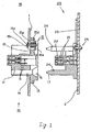
- Fig.1 is a sectional view showing the structure of a connector according to an embodiment of the present invention with an outer wall of device (i.e., auto-parts) to be assembled together.
- an outer wall of device i.e., auto-parts
- Fig.2 is a perspective view showing structure of a male member of the connector.
- Fig.3 is a perspective view showing the structure of a female member of the connector.
- Fig. 4 is a sectional view showing a structure of the connector in which the male and female members are joined together.
- Fig.5 (A)-(E) are perspective views showing differing aspects of the male member centrally located and moving up, down, to the left and to the right.
- Fig.6 is a perspective view showing an example of a prior art conventional connector.
- Fig.7 is a perspective view showing another example of a prior art conventional connector.
- Fig.1 is a sectional view showing the structure of a connector according to an embodiment of the present invention with an outer wall of device ( i.e., auto-parts) to be assembled together.
- Fig.2 and Fig.3 are perspective views of a male member10 and a female member 20 of the connector, respectively.
- Fig.4 is a sectional view showing the structure of the connector in which the male and female members are joined together.
- the male member10 includes male electrical terminals11, a housing 12 to house the male terminals 11, base plate13, guide holes 14, and a slightly movable attaching mechanism 15.
- Electric wires (not shown in Fig.1), which are extended from the electrical equipment held in the parts to which the male member10 is to be attached, are connected to rear end portions of the male electrical terminals 11.
- Two guide-holes14 are formed outside the housing12, wherein each guide-hole14 having a tip portion16 with an inner diameter which gets wider toward the front end of the guide-hole14.
- the principal part of the male member10, including the housing 12, the base plate13 and the guide-holes14, are made as an indivisible unit by projection of resin.
- the female member 20 includes female terminals 21, a housing 22 to house the female terminals 21, a base plate 23, guide-pins 24 and an attaching mechanism 25.
- Electric wires (not shown in Fig.1 ), which are extended from electrical equipment held in the other parts to which female member 20 is to be attached, are connected to rear end portions of the female electrical terminals 21.
- the guide-pins 24 are protruded forwardly from the base plate 23 around the housing 23.
- the guide-pins 24 have tip portions17 with outer diameters that become narrower towards the front ends of the guide-pins 24.
- the principal part of the female member 20, including the housing 22, the base plate 23 and the guide-pins 24, are also made as a indivisible unit by projection of resin.
- the words male and female are derived maily from the shapes of electrical terminals 11 and 21.
- the male connector10 is attached to the outer wall1 of the device in slightly movable manner by two slightly movable attaching mechanism 15 (only one of the two such mechanism is shown in Fig. 1).
- the slightly movable mechanism 15 includes through-holes15a formed through the base plate 13, bolts 15b which are inserted through the through-holes 15a, nuts 15c which are threading engaged to the tip portions of the bolts15b at the back side of the base plate13, cylindrical collars 15d surrounding the bolts 15b, and washers 15e placed between the tip portions of the collars 15d and the neck portion of the bolts 15b.
- the bolts 15b of the slightly movable attaching mechanism 15 are attached to the outer wall 1 in a slightly movable manner.
- the length of the collars15e surrounding the bolts15b is made slightly larger than the thickness of the base plate13 of the male member10.
- the inner diameter of the through-holes15a is made slightly larger than the outer diameter of the collars 15e, in this case by approximately 6 mm.
- the male member10 of the connector is attached to the outer wall 1 in a manner so that it can slide along the surface of the outer wall 1 within a maximum range determined by the difference of inner diameter of the through-holes15a and the outer diameter of the collar15e ( in this case +/- 6mm).
- Figs. 5(A)-(E) are perspective views showing aspects of the male member 10 moving up, down, to the left and to the right from the center position in each direction by 3mm.
- Fig.5 (A) shows the female member 10 located in a central position
- Fig.5(B) shows the male member10 moved to the left by 3mm from the central position.
- Fig.5 (C) shows the male member10 moved to the right by 3mm from the central position.
- Fig.5(D) shows the male member10 moved downwards by 3mm from the central position.
- Fig.5(E) shows the male member10 moved upwards by 3mm from the central position.
- the female member 20 of the connector is attached to the outer wall 2 of the other parts by two conventional threadingly attaching mechanisms 25 composed of bolts, nuts and washers in order to keep the appropriate rigidness, although in Fig.1, only one attaching mechanism 25 is shown.
- the male member10 which is attached to the outer wall1 in a slightly movable manner, and the female member 20, which is attached to the outer wall 2 are moved closer to each other as the parts or partial assembly are moved closer to the body of the automobile by means of being held in a robot arm or similar of an automatic assembling system.
- the male member 10 and female member 20 of the connector work as an automatic positioning mechanism.
- the tip portions17 of the guide-pins 24 will be inserted into the guide-holes14 without contacting to the inner walls of the guide-holes 14. However, the tip portions 17 of the guide-pins 24 will usually contact the inner walls of the guide-holes 14, because positioning between two members is not usually perfect. In this usual case, when both the male and female members are further moved closer together, a centering force for making the central axis of the guide-holes 14 coincide with the central axis of the guide-pins 24, are transmitted from the female member 20 to the male member10.
- the male member 10 is forced to very slightly slide over the surface of the outer wall1 due to the centering force to accept female the femember 20 therein. Under so-called self-alignment by the centering force, a joining of the housings 12 and 22 will be completed to accomplish mechanical and electrical connection between the electrical terminals 11 and 21.
- inner diameters of tip portion 16 of the guide-holes14 are made larger than the outer diameters of base portion of the guide pins 24 by about 6 mm and the male member 10 is made slightly slidable over the surface of the outer wall 1 at most +/_ 3 mm from the center position as described above.
- guide-pins 24 are provided to the female member20 and the guide-holes14 are provided to the male member10 , it is also possible to provide guide-pins24 to the male member10 and to provide-guide holes14 to the female member 20.
- slightly movable attaching mechanism25 which compensates for the positioning errors and the sizing errors can be eliminated, in special cases in which the positioning errors and the sizing errors are negligibly small, because of the small size of the parts or similar to be assembled.
- a connector according to present invention is attached to auto-parts.
- the connector of the present invention can be attached to other appropriate solid structures such as device, parts, element, as long as they have larger size than the connector.
- a connector of the present invention locations of both male member and female member of the connector are made definite, because both members are directly attached to parts or similar with appropriate rigidness, instead of being attached to the tip portions of flexible electric cables 5, as was done in prior art.
- the connector of the present invention make it easy to realize an automatic assembly system for the auto-parts which include electric parts.
- self-alignment and compensation of positioning errors and sizing error can be accomplished, by providing guide-pins 24 and guide-holes14 to one of the male or the female member, and by attaching at least one member to solid structures in a slightly movable manner.
- Both of the male member(10) and the female member (20) of the connector are attached to solid structures( 1, 2 ) directly, instead of being attached to tip portions of flexible electric cables extended from outside of the solid structures.
- the solid structures are parts such as auto-parts or partial assembly composed of a plurality of the parts or body such as a body of an automobile which are to be assembled together and which have a larger size than the size of the connector.
- One of the male member and the female members of the connector(20) includes at least one guide-pin( 24) protruding forwardly therefrom, whereas another (10) includes guide-holes (14) for accepting and guiding at least one guide-pin thereinto. At least one(10) of the male member and the female members of said connector is attached slightly movably to the solid structure(1).
Landscapes
- Details Of Connecting Devices For Male And Female Coupling (AREA)
- Connector Housings Or Holding Contact Members (AREA)
- Coupling Device And Connection With Printed Circuit (AREA)
Applications Claiming Priority (2)
| Application Number | Priority Date | Filing Date | Title |
|---|---|---|---|
| JP79624/96 | 1996-03-07 | ||
| JP8079624A JPH09245887A (ja) | 1996-03-07 | 1996-03-07 | コネクタ及びこのコネクタを取付けた自動車用部品 |
Publications (2)
| Publication Number | Publication Date |
|---|---|
| EP0794594A2 true EP0794594A2 (de) | 1997-09-10 |
| EP0794594A3 EP0794594A3 (de) | 1998-12-02 |
Family
ID=13695237
Family Applications (1)
| Application Number | Title | Priority Date | Filing Date |
|---|---|---|---|
| EP97103785A Withdrawn EP0794594A3 (de) | 1996-03-07 | 1997-03-06 | Verbinder und Fahrzeugteile mit einem solchen Verbinder |
Country Status (6)
| Country | Link |
|---|---|
| US (1) | US6155857A (de) |
| EP (1) | EP0794594A3 (de) |
| JP (1) | JPH09245887A (de) |
| KR (1) | KR100464608B1 (de) |
| CN (1) | CN1096128C (de) |
| TW (1) | TW374260B (de) |
Cited By (9)
| Publication number | Priority date | Publication date | Assignee | Title |
|---|---|---|---|---|
| DE19915142A1 (de) * | 1999-03-26 | 2000-10-05 | Geesthacht Gkss Forschung | Metallhaltiger Elektrodenwerkstoff wenigstens für Sekundärelemente und Verfahren zu seiner Herstellung |
| EP1158845A1 (de) * | 2000-05-25 | 2001-11-28 | Lucent Technologies Inc. | Baugruppenanordnung zur Montage innerhalb vorgegebener Toleranzen |
| EP1306933A3 (de) * | 2001-10-25 | 2005-08-17 | Erni Elektroapparate Gmbh | Führungssystem für Kontaktstecker |
| WO2009153011A3 (de) * | 2008-06-20 | 2010-03-04 | Airbus Operations Gmbh | Schnittstellenelement, flugzeuginnenaustattungsbauteil und verfahren zur montage eines flugzeuginnenaustattungsbauteils |
| WO2011154127A1 (de) * | 2010-06-08 | 2011-12-15 | Phoenix Contact Gmbh & Co. Kg | Elektrisches gerät mit einem steckverbinder und elektrische steckverbindung |
| WO2013150302A1 (en) * | 2012-04-03 | 2013-10-10 | Ifpl Group Limited | Electrical connectors |
| EP3849028A1 (de) * | 2020-01-09 | 2021-07-14 | Rosenberger Hochfrequenztechnik GmbH & Co. KG | Steckverbinderanordnung und elektrischer steckverbinder |
| IT202200017349A1 (it) * | 2022-08-17 | 2024-02-17 | Te Connectivity Italia Distribution Srl | Metodo e sistema per connessione ad accoppiamento cieco |
| EP4376230A1 (de) * | 2022-08-17 | 2024-05-29 | TE Connectivity Italia Distribution S.r.l. | Verfahren und system für blindverbindung |
Families Citing this family (32)
| Publication number | Priority date | Publication date | Assignee | Title |
|---|---|---|---|---|
| DE29922718U1 (de) * | 1999-12-23 | 2001-05-03 | Robert Bosch Gmbh, 70469 Stuttgart | Elektrischer Steckverbinder mit Führungs- und Zentrierhilfe |
| DE10017335B4 (de) * | 2000-04-07 | 2011-03-10 | Conti Temic Microelectronic Gmbh | Elektronische Baugruppe |
| JP3567856B2 (ja) * | 2000-06-08 | 2004-09-22 | 住友電装株式会社 | コネクタの支持構造 |
| JP3979078B2 (ja) * | 2001-12-14 | 2007-09-19 | 住友電装株式会社 | コネクタの嵌合構造 |
| DE10230376B4 (de) * | 2002-06-28 | 2005-04-28 | Amphenol Tuchel Elect | Einschubsteckverbinder mit Leerhub |
| DE20221891U1 (de) | 2002-07-05 | 2008-11-13 | Amphenol-Tuchel Electronics Gmbh | Einschubsteckverbinder mit Leerhub |
| JP4535987B2 (ja) * | 2005-11-18 | 2010-09-01 | 矢崎総業株式会社 | 可動コネクタ |
| JP2007280839A (ja) * | 2006-04-10 | 2007-10-25 | Hitachi Kokusai Electric Inc | 電子機器 |
| JP4748368B2 (ja) * | 2006-08-24 | 2011-08-17 | 横河電機株式会社 | 誤挿入防止構造 |
| JP5050823B2 (ja) * | 2007-12-10 | 2012-10-17 | 住友電装株式会社 | コネクタ |
| JP4950862B2 (ja) * | 2007-12-10 | 2012-06-13 | 矢崎総業株式会社 | 複合端子の製造方法 |
| CN101470489A (zh) * | 2007-12-27 | 2009-07-01 | 鸿富锦精密工业(深圳)有限公司 | Usb接口定位结构 |
| JP5163377B2 (ja) * | 2008-09-09 | 2013-03-13 | パナソニック株式会社 | 電子部品実装装置およびパーツフィーダ交換用台車 |
| US7914318B2 (en) * | 2008-11-25 | 2011-03-29 | GM Global Technology Operations LLC | Electrical connector |
| US20100195302A1 (en) * | 2009-02-03 | 2010-08-05 | Rigby William J | Flexible guiding module |
| JP5421798B2 (ja) * | 2010-01-15 | 2014-02-19 | 矢崎総業株式会社 | コネクタの固定構造 |
| JP5784902B2 (ja) * | 2010-12-20 | 2015-09-24 | 矢崎総業株式会社 | ワイヤハーネス |
| CN204167602U (zh) * | 2014-09-16 | 2015-02-18 | 欧品电子(昆山)有限公司 | 具有导向柱的电连接器 |
| CN104332759A (zh) * | 2014-11-12 | 2015-02-04 | 成都缤果科技有限公司 | 一种用于usb连接的定位机构 |
| CN105048180B (zh) * | 2015-08-18 | 2017-10-03 | 海盐虎溪线缆有限公司 | 一种多功能的音箱线连接装置 |
| JP6561784B2 (ja) * | 2015-11-12 | 2019-08-21 | いすゞ自動車株式会社 | 変速機の組付構造 |
| JP6458745B2 (ja) * | 2016-02-18 | 2019-01-30 | オムロン株式会社 | 装置ユニット |
| CN106159561B (zh) * | 2016-07-08 | 2018-08-10 | 捷星显示科技(福建)有限公司 | 一种可自动调整角度的公头母头接口自插机构 |
| CN106252913B (zh) * | 2016-08-26 | 2019-09-03 | 新乡市光明电器有限公司 | 接线器及其组装方法 |
| DE102018101048B4 (de) * | 2018-01-18 | 2019-08-08 | Amphenol Tuchel Industrial GmbH | Steckverbindergehäuse zur Montage an einer Montagewand |
| JP7550644B2 (ja) * | 2018-08-07 | 2024-09-13 | 本田技研工業株式会社 | バッテリパック |
| DE112020001478T5 (de) | 2019-03-27 | 2021-12-23 | Ihi Corporation | Gaszufuhrvorrichtung mit integriertem Inverter |
| JP7279775B2 (ja) * | 2019-03-27 | 2023-05-23 | 株式会社Ihi | インバータ一体型気体供給装置 |
| KR102128686B1 (ko) * | 2019-11-12 | 2020-06-30 | 한전케이피에스 주식회사 | 커넥터 조립체 |
| EP4343982A1 (de) * | 2022-09-26 | 2024-03-27 | Valeo Vision | Elektrischer verbinder für eine kraftfahrzeuglampe |
| KR102805349B1 (ko) * | 2022-10-31 | 2025-05-14 | 주식회사 유라 | 커넥터 |
| DE102024120501A1 (de) | 2024-07-19 | 2026-01-22 | Connaught Electronics Ltd. | Steuergerätanordnung und Steckverbinderausrichtungsvorrichtung für eine Steuergerätanordnung |
Family Cites Families (15)
| Publication number | Priority date | Publication date | Assignee | Title |
|---|---|---|---|---|
| US4647130A (en) * | 1985-07-30 | 1987-03-03 | Amp Incorporated | Mounting means for high durability drawer connector |
| DE3536142A1 (de) * | 1985-10-10 | 1987-04-16 | Opel Adam Ag | Mehrpolige, als steckverbindung ausgebildete elektrische verbindung zwischen zwei gelenkig miteinander verbundenen bauteilen, insbesondere zwischen karosserie und seitentuer von kraftfahrzeugen |
| US4954085A (en) * | 1987-07-24 | 1990-09-04 | Honda Giken Kogyo Kabushiki Kaisha | Wiring structure |
| JPH02116486A (ja) * | 1988-10-25 | 1990-05-01 | Ohara Kk | ロボット用ガンチェンジャ |
| JPH0527814Y2 (de) * | 1988-02-09 | 1993-07-15 | ||
| US4943109A (en) * | 1988-08-09 | 1990-07-24 | Ford Motor Company | Automotive door assembly having a plug-in electrified interior panel |
| US4915641A (en) * | 1988-08-31 | 1990-04-10 | Molex Incorporated | Modular drawer connector |
| JPH0547438A (ja) * | 1991-08-17 | 1993-02-26 | Furukawa Electric Co Ltd:The | ワイヤハーネスの接続方法 |
| JPH074780Y2 (ja) * | 1991-10-30 | 1995-02-01 | モレックス インコーポレーテッド | 静電気防止コネクタ |
| US5385481A (en) * | 1991-12-20 | 1995-01-31 | Tandem Computers Incorporated | Alignment mechanism for blind-matable connection for two or more connectors |
| US5197896A (en) * | 1992-02-28 | 1993-03-30 | Amp Incorporated | Float mounting an electrical connector |
| JP2916564B2 (ja) * | 1992-12-04 | 1999-07-05 | 矢崎総業株式会社 | 多極コネクタの接続構造 |
| JPH06325823A (ja) * | 1993-05-11 | 1994-11-25 | Kansei Corp | コネクタ装置 |
| US5391091A (en) * | 1993-06-30 | 1995-02-21 | American Nucleonics Corporation | Connection system for blind mate electrical connector applications |
| US5622511A (en) * | 1995-12-11 | 1997-04-22 | Intel Corporation | Floating connector housing |
-
1996
- 1996-03-07 JP JP8079624A patent/JPH09245887A/ja active Pending
-
1997
- 1997-02-26 US US08/803,920 patent/US6155857A/en not_active Expired - Lifetime
- 1997-02-28 KR KR1019970006422A patent/KR100464608B1/ko not_active Expired - Fee Related
- 1997-03-06 EP EP97103785A patent/EP0794594A3/de not_active Withdrawn
- 1997-03-06 CN CN97109988.XA patent/CN1096128C/zh not_active Expired - Fee Related
- 1997-04-07 TW TW086104348A patent/TW374260B/zh not_active IP Right Cessation
Cited By (15)
| Publication number | Priority date | Publication date | Assignee | Title |
|---|---|---|---|---|
| DE19915142B4 (de) * | 1999-03-26 | 2006-05-04 | Gkss-Forschungszentrum Geesthacht Gmbh | Metallhaltiger Elektrodenwerkstoff für Primär- und Sekundärelemente |
| DE19915142A1 (de) * | 1999-03-26 | 2000-10-05 | Geesthacht Gkss Forschung | Metallhaltiger Elektrodenwerkstoff wenigstens für Sekundärelemente und Verfahren zu seiner Herstellung |
| EP1158845A1 (de) * | 2000-05-25 | 2001-11-28 | Lucent Technologies Inc. | Baugruppenanordnung zur Montage innerhalb vorgegebener Toleranzen |
| EP1306933A3 (de) * | 2001-10-25 | 2005-08-17 | Erni Elektroapparate Gmbh | Führungssystem für Kontaktstecker |
| US8602358B2 (en) | 2008-06-20 | 2013-12-10 | Airbus Operations Gmbh | Interface element, aircraft interior equipment component and method for installing an aircraft interior equipment component |
| WO2009153011A3 (de) * | 2008-06-20 | 2010-03-04 | Airbus Operations Gmbh | Schnittstellenelement, flugzeuginnenaustattungsbauteil und verfahren zur montage eines flugzeuginnenaustattungsbauteils |
| US8951055B2 (en) | 2010-06-08 | 2015-02-10 | Phoenix Contact Gmbh & Co. Kg | Electrical device with a plug-type connector and electrical plug-type connection |
| WO2011154127A1 (de) * | 2010-06-08 | 2011-12-15 | Phoenix Contact Gmbh & Co. Kg | Elektrisches gerät mit einem steckverbinder und elektrische steckverbindung |
| WO2013150302A1 (en) * | 2012-04-03 | 2013-10-10 | Ifpl Group Limited | Electrical connectors |
| GB2515710A (en) * | 2012-04-03 | 2014-12-31 | Ifpl Group Ltd | Electrical connectors |
| EP3849028A1 (de) * | 2020-01-09 | 2021-07-14 | Rosenberger Hochfrequenztechnik GmbH & Co. KG | Steckverbinderanordnung und elektrischer steckverbinder |
| WO2021140091A1 (de) * | 2020-01-09 | 2021-07-15 | Rosenberger Hochfrequenztechnik Gmbh & Co. Kg | Steckverbinderanordnung und elektrischer steckverbinder |
| US12294179B2 (en) | 2020-01-09 | 2025-05-06 | Rosenberger Hochfrequenztechnik Gmbh & Co. Kg | Plug-in connector arrangement and electrical plug-in connector |
| IT202200017349A1 (it) * | 2022-08-17 | 2024-02-17 | Te Connectivity Italia Distribution Srl | Metodo e sistema per connessione ad accoppiamento cieco |
| EP4376230A1 (de) * | 2022-08-17 | 2024-05-29 | TE Connectivity Italia Distribution S.r.l. | Verfahren und system für blindverbindung |
Also Published As
| Publication number | Publication date |
|---|---|
| CN1096128C (zh) | 2002-12-11 |
| US6155857A (en) | 2000-12-05 |
| JPH09245887A (ja) | 1997-09-19 |
| EP0794594A3 (de) | 1998-12-02 |
| CN1169043A (zh) | 1997-12-31 |
| KR970068027A (ko) | 1997-10-13 |
| TW374260B (en) | 1999-11-11 |
| KR100464608B1 (ko) | 2006-03-14 |
Similar Documents
| Publication | Publication Date | Title |
|---|---|---|
| EP0794594A2 (de) | Verbinder und Fahrzeugteile mit einem solchen Verbinder | |
| JP3204397B2 (ja) | マイクロピンのコネクタ機構 | |
| US5980290A (en) | Coaxial electric connector element with movable contact and coaxial electrical connector comprising such a connector | |
| JP3006662B2 (ja) | 電気接続箱 | |
| EP0889559B1 (de) | Verfahren zum Herstellen eines Verbinders für eine Leiterplatte | |
| US4629351A (en) | Fitting indicating mechanism in screw type connector housings | |
| EP0582264B1 (de) | Elektrischer Verbinder für gedruckte Leiterplatten | |
| EP1608044B1 (de) | Konstruktion und Verfahren zum Verbinden eines Zwischensteckers und einem oder mehreren elektrischen Komponenten | |
| DE19809492A1 (de) | Elektrischer Verbinder | |
| JP2019096471A (ja) | 端子ホルダ、ワイヤハーネス、固定構造 | |
| US5676552A (en) | Wire harness device for instrument panel | |
| US4813885A (en) | Wiring harness connector retainer | |
| JP3698244B2 (ja) | 樹脂充填コネクタとその製造方法 | |
| JP2516089B2 (ja) | コネクタの結線構造とその方法 | |
| US4929182A (en) | Mounting construction for on-vehicle electrical connection apparatus | |
| US20070281543A1 (en) | Multipole Pin Strip | |
| US6428332B1 (en) | Connector for use on board | |
| JPH08213104A (ja) | 電気接続装置 | |
| CN1202598C (zh) | 用于阴性bnc连接部件的导向器和包括该导向器的电气设备 | |
| US4859198A (en) | Contact assembly | |
| US6893271B2 (en) | Circuit board assembly, main and connector boards, and connector pins for same | |
| US5910347A (en) | Precision molded cylinders | |
| EP0779680A2 (de) | Steckverbinderzusammenbau für Kabelbündel und Verbindungsmethode | |
| US11296438B1 (en) | Electrical connector assembly having a terminal-less connection system | |
| JP3273975B2 (ja) | コネクタ |
Legal Events
| Date | Code | Title | Description |
|---|---|---|---|
| PUAI | Public reference made under article 153(3) epc to a published international application that has entered the european phase |
Free format text: ORIGINAL CODE: 0009012 |
|
| AK | Designated contracting states |
Kind code of ref document: A2 Designated state(s): FR IT |
|
| PUAL | Search report despatched |
Free format text: ORIGINAL CODE: 0009013 |
|
| AK | Designated contracting states |
Kind code of ref document: A3 Designated state(s): FR IT |
|
| 17P | Request for examination filed |
Effective date: 19990225 |
|
| STAA | Information on the status of an ep patent application or granted ep patent |
Free format text: STATUS: THE APPLICATION IS DEEMED TO BE WITHDRAWN |
|
| 18D | Application deemed to be withdrawn |
Effective date: 20060728 |