EP0795340B1 - Ballonkatheter - Google Patents
Ballonkatheter Download PDFInfo
- Publication number
- EP0795340B1 EP0795340B1 EP97301599A EP97301599A EP0795340B1 EP 0795340 B1 EP0795340 B1 EP 0795340B1 EP 97301599 A EP97301599 A EP 97301599A EP 97301599 A EP97301599 A EP 97301599A EP 0795340 B1 EP0795340 B1 EP 0795340B1
- Authority
- EP
- European Patent Office
- Prior art keywords
- balloon
- tube portion
- tube
- stent
- stretched
- Prior art date
- Legal status (The legal status is an assumption and is not a legal conclusion. Google has not performed a legal analysis and makes no representation as to the accuracy of the status listed.)
- Expired - Lifetime
Links
- 239000004033 plastic Substances 0.000 claims description 26
- 229920003023 plastic Polymers 0.000 claims description 26
- 229920001169 thermoplastic Polymers 0.000 claims description 7
- 239000004416 thermosoftening plastic Substances 0.000 claims description 7
- 229920001778 nylon Polymers 0.000 claims description 6
- -1 polyethylene Polymers 0.000 claims description 6
- 239000004698 Polyethylene Substances 0.000 claims description 5
- 229920000573 polyethylene Polymers 0.000 claims description 5
- 239000004677 Nylon Substances 0.000 claims description 4
- 238000005482 strain hardening Methods 0.000 claims description 4
- 238000002513 implantation Methods 0.000 claims description 3
- 238000009472 formulation Methods 0.000 claims description 2
- 239000000203 mixture Substances 0.000 claims description 2
- 238000000034 method Methods 0.000 description 8
- 210000001367 artery Anatomy 0.000 description 5
- 239000000463 material Substances 0.000 description 5
- 238000004519 manufacturing process Methods 0.000 description 4
- JHWNWJKBPDFINM-UHFFFAOYSA-N Laurolactam Chemical compound O=C1CCCCCCCCCCCN1 JHWNWJKBPDFINM-UHFFFAOYSA-N 0.000 description 3
- 229920000299 Nylon 12 Polymers 0.000 description 3
- 238000001356 surgical procedure Methods 0.000 description 3
- 210000004351 coronary vessel Anatomy 0.000 description 2
- IFNDEOYXGHGERA-UHFFFAOYSA-N 2-methoxy-5-methylphenol Chemical compound COC1=CC=C(C)C=C1O IFNDEOYXGHGERA-UHFFFAOYSA-N 0.000 description 1
- 239000004952 Polyamide Substances 0.000 description 1
- 229920006020 amorphous polyamide Polymers 0.000 description 1
- 238000002399 angioplasty Methods 0.000 description 1
- 230000015572 biosynthetic process Effects 0.000 description 1
- 210000004204 blood vessel Anatomy 0.000 description 1
- 229920006147 copolyamide elastomer Polymers 0.000 description 1
- 229920001577 copolymer Polymers 0.000 description 1
- 230000001419 dependent effect Effects 0.000 description 1
- PRAKJMSDJKAYCZ-UHFFFAOYSA-N dodecahydrosqualene Natural products CC(C)CCCC(C)CCCC(C)CCCCC(C)CCCC(C)CCCC(C)C PRAKJMSDJKAYCZ-UHFFFAOYSA-N 0.000 description 1
- 230000000694 effects Effects 0.000 description 1
- 238000010438 heat treatment Methods 0.000 description 1
- 230000008520 organization Effects 0.000 description 1
- 229920002647 polyamide Polymers 0.000 description 1
- 229920000728 polyester Polymers 0.000 description 1
- 229920000642 polymer Polymers 0.000 description 1
- 208000037803 restenosis Diseases 0.000 description 1
- 239000002904 solvent Substances 0.000 description 1
- 230000002269 spontaneous effect Effects 0.000 description 1
- 230000001954 sterilising effect Effects 0.000 description 1
- 238000004659 sterilization and disinfection Methods 0.000 description 1
- 239000012815 thermoplastic material Substances 0.000 description 1
Images
Classifications
-
- A—HUMAN NECESSITIES
- A61—MEDICAL OR VETERINARY SCIENCE; HYGIENE
- A61M—DEVICES FOR INTRODUCING MEDIA INTO, OR ONTO, THE BODY; DEVICES FOR TRANSDUCING BODY MEDIA OR FOR TAKING MEDIA FROM THE BODY; DEVICES FOR PRODUCING OR ENDING SLEEP OR STUPOR
- A61M25/00—Catheters; Hollow probes
- A61M25/10—Balloon catheters
- A61M25/1027—Making of balloon catheters
- A61M25/1029—Production methods of the balloon members, e.g. blow-moulding, extruding, deposition or by wrapping a plurality of layers of balloon material around a mandril
Definitions
- a balloon catheter in which the balloon in its non-inflated configuration has a smooth, cylindrical wall, and is no greater in diameter than the remainder of the catheter.
- the balloon in its original form, is a tube made of an elastically expandable, work-hardenable plastic, such as known forms of nylon or polyethylene (polyethylene terephalate).
- a stated advantage of such a balloon lies on the fact that as the balloon expands with increasing internal pressure, there is a pressure range which the work-hardening primarily takes place which has an effect of reducing or eliminating the expansion of the balloon with increasing pressure.
- a doctor expands the balloon within a patient to this pressure range, he or she can know with confidence that the balloon diameter is no greater than a predetermined maximum diameter, without the need for a direct observation.
- a popular surgical procedure for preventing restenosis in arteries utilizes a catheter dilatation balloon which is surrounded by an expandable tubular stent, for example a wire stent, or an apertured tube stent of the type sold by the Johnson and Johnson Corporation.
- the balloon and stent are positioned as desired within an artery or other vessel lumen of a patient. Then the balloon is expanded, to expand the stent to a desired configuration. It is desirable to avoid overexpansion from such a balloon as the stent is being expanded.
- a stent balloon tends to expand one end or the other first, rather than first in the middle while in the process of expanding the stent, the stent can be driven off the balloon by such asymmetric expansion, so that the stent becomes only partially expanded. This of course can be a great problem during surgery, and may result in the stent becoming positioned improperly in the expanded configuration.
- a catheter balloon which can be very narrow prior to inflation, and which can inflate in a circumferentially uniform manner, which is predictably dependent on the inflation pressure, for optimum implantation of stents within the body, and also for other medical uses which are customary for catheter balloons.
- Claim 1 is drafted such that features known from EP-A-0 485 903 are placed in the preamble.
- a catheter balloon having a stent thereover is provided.
- the balloon may comprise:
- a balloon may be made from thermoplastic tube by radially stretching at least a portion of the thermoplastic tube while causing a central section of the tube portion to stretch to a lesser wall thickness than end sections of the tube portion.
- the balloon can be biaxially oriented by the radial stretching step and the longitudinal stretching step. This characteristic of many plastics is a well-known and understood property.
- a central section of the tube portion preferably may be of lesser wall thickness than end sections of the same tube portion, at least initially more radial expansion of the central section of the tube portion takes place than end sections thereof.
- a central portion of the stent can be expanded first within the patient, with the entire stent being subsequently expanded by further inflation of the balloon formed from the tube portion, to provide spontaneous assurance that the stent will not shift on the balloon during the inflation of the balloon and expansion of the stent.
- the balloon's radial expansion tends to begin in the middle, and spreads to the ends.
- a surrounding, centered stent is not pushed off of the balloon, as may be the case if the balloon expands at one end first.
- the balloon's radial expansion may cause molecular orientation of the tube portion, resulting in work-hardening, so that, at a predetermined pressure range, the diameter of the balloon formed from the tube portion is relatively constant and known.
- step A above at least some of the plastic tube portion may be longitudinally stretched to create increased longitudinal molecular orientation.
- the details of this and the above stretching steps may be performed as described in Pinchuk et al. U.S. Patent No. 5,156,612, with the exception of that, contrary to the teachings of that patent, the final balloon inflation step disclosed therein takes place within the patient, and not as a process step in the manufacturing of the balloon and catheter.
- the balloon-forming plastic tube may be made of stretchable forms of nylon and polyethylene polymers or copolymers (such as poly(ethylene-propylene) which exhibit desired properties for use herein.
- nylons 612, 11, and 12 may be used,typically of a relative solution viscosity of about 1.6 to 2.2 as determined by the Internation Standards Organization Test ISO 307/DIN 53 727, with m-creosol as a solvent, employing a concentration of 0.5 gm. of nylon 12 per 100 ml. of M-creosol. With nylon 12, a relative solution viscosity of about 2.1 is preferred.
- the tube portion which is to be inserted into the patient preferably has a diameter prior to said pressurizing of step (C) above within the patient of no more than about twice the minimum diameter of adjacent tubing of the catheter.
- the pre-expanded tube portion discussed above may have a diameter of less than 50 percent over the minimum diameter of adjacent catheter tubing, and is preferably of substantially equal diameter to such catheter tubing, so that the tube portion which is to become the balloon may slide easily along with the rest of the catheter tubing into a non-expanded, tubular stent, and into a blood vessel or body lumen without difficulty.
- the formed balloon preferably has an outer wall that is smooth and free of folds, contrary to the presently conventional catheter dilatation balloons for angioplasty and the like. This is rendered possible by the stretching capabil ity of the catheter tube portion to form the desired balloon, while at the same time one or more desired maximum balloon expansion diameters (one larger than the other) may optionally be achieved at predetermined pressure ranges in the manner described in the cited Miller patent application.
- the length of the plastic portion which is radially stretched in step (A) above may be less than and included in the length of the plastic portion which is longitudinally stretched in step (B).
- the stent when applied to the balloon described herein, may be preferably longitudinally centered on the length of the plastic portion which is radially stretched in step (A).
- a central portion of the balloon of this invention preferably tends to expand first, causing a central portion of the stent to expand first relative to end portions thereof.
- the end parts of the plastic tube portion longitudinally stretched will expand also, to cause end portions of the stent to expand as well.
- the stent will not slide off the balloon, avoiding the problem which has been encountered in some surgical procedures.
- orientable thermoplastic materials may be used as well as nylon and polyethylene as orientable thermoplastics for use as a catheter balloon in accordance with this invention. They may be selected from other materials such as polyamide block copolymers, polyamide copolymers, amorphous polyamides, and polyester copolymers, for example.
- the molecular orientation of the tube is accomplished by applying a force greater than the material's yield point to cause stretching, but less that its ultimate tensile strength.
- control of the location of the material which is stretched may be made by the local application of heat, to lower the yield point of the desired area where radial expansion is to be achieved.
- a gradation of heat applied can cause the middle of the newly-formed balloon to stretch more than end portions and thus to have a lower wall thickness.
- the tube may initially have a thinner central portion.
- the tubing section may be re-oriented sequentially by longitudinal stretching, followed by radial pressurized stretching, without a significant loss of shape-forming capability. It may be desirable in some cases to sequentially repeat the respective steps (A) and (B) several times, as may be desired.
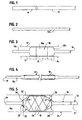
- Fig. 1 is a perspective view of a portion of a plastic tube, or if desired, an entire length of tube, which is to be biaxially oriented in accordance with this invention for the formation of a catheter balloon;
- a method for preparing a catheter balloon for inflation and for inflating the balloon is illustrated.
- a plastic tube 10 is provided in accordance with Fig. 1, the plastic material of the tube preferably having the capability to undergo biaxial orientation.
- a relatively low crystalline nylon 12 may be used to manufacture tube 10.
- Tube 10 may be either bonded to a catheter tube 12 during the manufacturing steps of the method of this invention, or subsequently, prior to use of expanding the balloon within the patient. Alternatively, tube 10 may be integrally extruded with catheter tube 12.
- tube 10 is longitudinally stretched as in Fig. 2 to create a desired, increased, longitudinal molecular orientation relative to the tube, as illustrated by tube 10a, which comprises the stretched portion of tube 10 after the first step of processing.
- Specific conditions for this processing may vary, depending upon the materials, but are generally familiar to those skilled in the art of the molecular orientation of plastics.
- the pertinent disclosures of Pinchuk et al. U.S. Patent No. 5,156,612 may be utilized in developing a specific process, the disclosures of that patent being incorporated by reference herein.
- Fig. 3 corresponds to method step (A) above, as previously discussed.
- Tubing 10a from Fig. 2 may have a portion thereof heated by a conventional heater 14, so that the yield point of the heated plastic drops relative to the remaining plastic of tube 10b, which is tube 10a as modified by the processing step of Fig. 3.
- lumen 16 of the tube may be pressurized in a mold 17 to restrict balloon expansion and to cause a preliminary balloon 18 to form.
- a desired, increased radial expansion and molecular orientation is provided to balloon 18, resulting in at least a degree of biaxial orientation to balloon 18.
- Heater 14 may have a central section 19 that heats a central portion 18a of balloon 18 slightly more than the terminal portions 18b of the balloon.
- the wall thickness of balloon 18a may be slightly reduced relative to the wall thickness of balloon end portions 18b.
- Mold 17 may have an appropriate outward bulge if desired to accommodate the added stretching and thinning of the walls of central section 18a.
- the wall thickness of central catheter balloon portion 18a may be approximately 7.6 ⁇ m to 38.1 ⁇ m (0.0003 to 0.0015 inch) while the wall thicknesses of end portions 18b may be approximately 5 ⁇ m (0.0002 inch) thicker than the wall thickness of portion 18a after the expansion of Fig. 3 and prior to the processing of Fig. 4.
- step (B) is step (B) as previously described, in which tube portion 10b is longitudinally stretched to form tube portion 10c as shown in Fig. 4.
- Balloon 18 exhibits a reduction in diameter, with the prior internal pressurizing within the tube being released to facilitate the desired longitudinal stretching, for further longitudinal molecular orientation of the plastic tube.
- the balloon formed has an equal diameter at its opposed ends.
- catheter portion 10c may be attached to the rest of the catheter if that has not been previously done.
- catheter 12 is shown carrying plastic tube portion 10c.
- Lumen 16 communicates with an inflation lumen 17 of the rest of catheter 12.
- Tube portion has a closed, distal end 19 in this embodiment.
- multiple lumen catheters may be provided in which at least one lumen passes through end 19 while the inflation lumen terminates in the area of balloon 18.
- Balloon 18 carries a tubular, crossing-wire, or apertured-tube, expansible stent 22 of conventional design, with the catheter 12 and stent 22 being shown to be occupying an artery 24 of a patient.
- Stent 22 is placed about plastic tube portion 10c while in the collapsed configuration of Fig. 4. Then, when balloon 18 and stent 22 have been positioned at the proper place in artery 24, the lumen of catheter 10c is inflated to a predetermined pressure. Balloon 18 expands as shown in Fig. 5, with the middle of balloon portion 18 being centrally located within stent 22.
- the center of balloon 18 expands first, since it is of slightly reduced wall thickness, expanding a central portion 26 of stent 22 outwardly more rapidly than the expansion of the end portions 28 of the stent. This causes the stent to remain in position on the balloon, and not to be forced off the balloon by its expansion, as may take place when expansion begins at an end portion of the stent. Following this, end portions 30 of the balloon may be inflated more than shown, to drive added portions of the stent 22 radially outwardly into a fully expanded configuration, as shown in dotted lines.
- tubing 10c can be depressurized, causing balloon 18 to collapse, so that catheter 20 and its distal tube section 10c may be withdrawn, leaving the expanded stent 22 behind in the artery.
- the stent may be expanded with more uniform circumferential pressures against all of its inner surfaces (disregarding the issue of central preexpansion of the balloon). This results in better stent placement than can often be achieved with catheter balloons of the prior art. Also, balloon 18 can cease its expansion at a predetermined diameter in a predetermined elevated pressure range due to work hardening, which increases the assurance that the balloon will not be over inflated.
Landscapes
- Health & Medical Sciences (AREA)
- Heart & Thoracic Surgery (AREA)
- Engineering & Computer Science (AREA)
- Life Sciences & Earth Sciences (AREA)
- Anesthesiology (AREA)
- Child & Adolescent Psychology (AREA)
- Biophysics (AREA)
- Pulmonology (AREA)
- Manufacturing & Machinery (AREA)
- Biomedical Technology (AREA)
- Hematology (AREA)
- Animal Behavior & Ethology (AREA)
- General Health & Medical Sciences (AREA)
- Public Health (AREA)
- Veterinary Medicine (AREA)
- Media Introduction/Drainage Providing Device (AREA)
Claims (13)
- Katheterballon, umfassend ein elastisches thermoplastisches Rohr (10), wobei:dadurch gekennzeichnet, daß(A) mindestens ein Teil (10a) des Kunststoffrohres (10) radial gestreckt wurde, um einer Kaltverfestigung unterworfen zu werden, bis der radial gestreckte Rohrteil ((B) 10a) eine gewünschte Zunahme der molekularen Orientierung aufweist;(C) mindestens ein Teil (10b) des Rohrteils längs gestreckt wurde, um eine gewünschte, in Längsrichtung des Rohres (10) eine erhöhte molekulare Orientierung hervorzurufen,
und(D) der Rohrteil (10a) als Teil eines Katheters (12) zum Einsetzen in einen Patienten dient, wobei der
Rohrteil (10a) ein Lumen hat, das innerhalb des Patienten unter Druck gesetzt werden kann, das Unterdrucksetzen des Lumens dieses Rohrteils eine radiale Dehnung des Rohrteils bewirkt, derart, daß ein zentraler Abschnitt des Kunststoffrohrteils zumindest anfänglich um ein größeres Maß radial gedehnt wird als die äußeren Teile des Rohrteils;
das Lumen von einem dehnbaren Stent zum Implantieren in dem Patienten umgeben ist, wodurch der Stent (22) gedehnt und implantiert werden kann. - Ballon nach Anspruch 1, wobei das Kunststoffrohr (10) eine Formulierung umfaßt, die aus der Gruppe ausgewählt ist, die aus Nylon und Polyethylen besteht.
- Ballon nach Anspruch 1, wobei der Rohrteil (10b), vor dem Unterdrucksetzen des Lumens, einen Durchmesser von nicht mehr als dem zweifachen des Mindestdurchmessers des benachbarten Rohres des Katheters hat, und der Rohrteil eine Außenwand hat, die glatt und frei von Falten ist.
- Ballon nach einem der vorhergehenden Ansprüche, wobei die Länge des radial gestreckten Rohrteils geringer als die Länge des längs gestreckten Rohrteils ist und in der Länge desselben eingeschlossen ist.
- Ballon nach Anspruch 4, wobei der Stent (22) längs zentriert ist auf die Länge (10c) des radial gestreckten Rohrteils (10b).
- Ballon nach Anspruch 5, wobei der dehnbare Stent (22) länger als die Länge des radial gestreckten Rohrteils (10a) ist.
- Ballon nach einem der vorhergehenden Ansprüche, wobei der radial gestreckte Rohrteil (10a) des elastisch thermoplastischen Rohres einen zentralen Abschnitt des Rohrteils (10a) bildet, der auf eine geringere Wanddicke als äußere Abschnitte des Rohrteils gestreckt ist.
- Ballon nach einem der vorhergehenden Ansprüche, wobei das Lumen des Rohrteils (10c), nach Wegnahme des Drucks, seine radiale Dehnung verringert, so daß der Rohrteil (10c) aus dem gedehnten Stent (22) herausgezogen werden kann.
- Ballon nach einem der vorhergehenden Ansprüche, der an einem Katheterrohr (12) befestigt ist.
- Ballon nach einem der vorhergehenden Ansprüche, wobei die Moleküle des Kunststoffrohrteils biaxial orientiert sind.
- Ballon nach einem der vorhergehenden Ansprüche, wobei der Rohrteil vor dem Unterdrucksetzen des Lumens einen Durchmesser von nicht mehr als dem Zweifachen des Mindestdurchmessers des benachbarten Rohres des Katheters hat, und der Rohrteil eine Außenwand hat, die glatt und frei von Falten ist.
- Ballon nach einem der vorhergehenden Ansprüche, wobei die Länge des radial gestreckten Rohrteils geringer als die Länge des längs gestreckten Rohrteils ist.
- Ballon nach einem der vorhergehenden Ansprüche, wobei der Stent (22) auf die Länge (10c) des gestreckten Rohrteils längs zentriert ist.
Applications Claiming Priority (2)
| Application Number | Priority Date | Filing Date | Title |
|---|---|---|---|
| US614399 | 1996-03-12 | ||
| US08/614,399 US5643279A (en) | 1996-03-12 | 1996-03-12 | Method of catheter balloon manufacture and use |
Publications (3)
| Publication Number | Publication Date |
|---|---|
| EP0795340A2 EP0795340A2 (de) | 1997-09-17 |
| EP0795340A3 EP0795340A3 (de) | 1998-03-11 |
| EP0795340B1 true EP0795340B1 (de) | 2003-12-03 |
Family
ID=24461088
Family Applications (1)
| Application Number | Title | Priority Date | Filing Date |
|---|---|---|---|
| EP97301599A Expired - Lifetime EP0795340B1 (de) | 1996-03-12 | 1997-03-11 | Ballonkatheter |
Country Status (5)
| Country | Link |
|---|---|
| US (3) | US5643279A (de) |
| EP (1) | EP0795340B1 (de) |
| JP (2) | JP4509230B2 (de) |
| CA (1) | CA2199549C (de) |
| DE (1) | DE69726481T2 (de) |
Cited By (1)
| Publication number | Priority date | Publication date | Assignee | Title |
|---|---|---|---|---|
| US7654264B2 (en) | 2006-07-18 | 2010-02-02 | Nellcor Puritan Bennett Llc | Medical tube including an inflatable cuff having a notched collar |
Families Citing this family (47)
| Publication number | Priority date | Publication date | Assignee | Title |
|---|---|---|---|---|
| US8280682B2 (en) * | 2000-12-15 | 2012-10-02 | Tvipr, Llc | Device for monitoring movement of shipped goods |
| US6602281B1 (en) * | 1995-06-05 | 2003-08-05 | Avantec Vascular Corporation | Radially expansible vessel scaffold having beams and expansion joints |
| US5868705A (en) * | 1996-05-20 | 1999-02-09 | Percusurge Inc | Pre-stretched catheter balloon |
| US6554795B2 (en) | 1997-03-06 | 2003-04-29 | Medtronic Ave, Inc. | Balloon catheter and method of manufacture |
| US5868783A (en) * | 1997-04-16 | 1999-02-09 | Numed, Inc. | Intravascular stent with limited axial shrinkage |
| US5954737A (en) * | 1997-12-19 | 1999-09-21 | Neurovasx, Inc. | Thrombus macerator catheter |
| WO2009117663A2 (en) | 2008-03-20 | 2009-09-24 | Medrad, Inc. | Direct stream hydrodynamic catheter system |
| US9586023B2 (en) | 1998-02-06 | 2017-03-07 | Boston Scientific Limited | Direct stream hydrodynamic catheter system |
| US6319229B1 (en) | 1998-02-19 | 2001-11-20 | Medtronic Percusurge, Inc. | Balloon catheter and method of manufacture |
| DE19839646A1 (de) | 1998-08-31 | 2000-03-09 | Jomed Implantate Gmbh | Stent |
| AU6404899A (en) * | 1998-09-30 | 2000-04-17 | Jay S. Yadav | Stent delivery system |
| JP2000217924A (ja) * | 1999-02-01 | 2000-08-08 | Kanegafuchi Chem Ind Co Ltd | 拡張カテーテル用拡張体およびその製造方法 |
| JP2001269410A (ja) * | 2000-03-24 | 2001-10-02 | Aisin Seiki Co Ltd | バルーンカテーテル |
| SE524080C2 (sv) * | 2000-05-19 | 2004-06-22 | Premetec Ab | Anordning med slang |
| US7037318B2 (en) * | 2000-12-18 | 2006-05-02 | Boston Scientific Scimed, Inc. | Catheter for controlled stent delivery |
| US20040082859A1 (en) | 2002-07-01 | 2004-04-29 | Alan Schaer | Method and apparatus employing ultrasound energy to treat body sphincters |
| US7189229B2 (en) * | 2002-09-16 | 2007-03-13 | Prorhythm, Inc. | Balloon alignment and collapsing system |
| US6808524B2 (en) * | 2002-09-16 | 2004-10-26 | Prorhythm, Inc. | Balloon alignment and collapsing system |
| US7128868B2 (en) * | 2003-01-10 | 2006-10-31 | Boston Scientific Scimed, Inc. | Balloon wing forming apparatus and method |
| WO2004073505A2 (en) * | 2003-02-20 | 2004-09-02 | Prorhythm, Inc. | Cardiac ablation devices |
| DE10331169A1 (de) * | 2003-07-09 | 2005-02-10 | Basf Ag | Gehäuseschale für ein elektronisches Gerät |
| US7727442B2 (en) * | 2003-07-10 | 2010-06-01 | Boston Scientific Scimed, Inc. | Medical device tubing with discrete orientation regions |
| JP4898985B2 (ja) * | 2003-07-31 | 2012-03-21 | クック メディカル テクノロジーズ エルエルシー | 複数の医療装置を導入するためのシステム及び方法 |
| US7635510B2 (en) * | 2004-07-07 | 2009-12-22 | Boston Scientific Scimed, Inc. | High performance balloon catheter/component |
| US20080275393A1 (en) * | 2004-08-24 | 2008-11-06 | Bonnette Michael J | Isolation thrombectomy catheter system |
| US20060182907A1 (en) * | 2005-02-11 | 2006-08-17 | Boston Scientific Scimed, Inc. | Novel microfibrillar reinforced polymer-polymer composites for use in medical devices |
| US8162878B2 (en) * | 2005-12-05 | 2012-04-24 | Medrad, Inc. | Exhaust-pressure-operated balloon catheter system |
| US10499937B2 (en) | 2006-05-19 | 2019-12-10 | Recor Medical, Inc. | Ablation device with optimized input power profile and method of using the same |
| US8926620B2 (en) | 2006-08-25 | 2015-01-06 | Kyphon Sarl | Apparatus and methods for use of expandable members in surgical applications |
| US8043362B2 (en) * | 2006-08-25 | 2011-10-25 | Kyphon Sarl | Apparatus and methods for use of expandable members in surgical applications |
| ITMI20062333A1 (it) | 2006-12-05 | 2008-06-06 | Mario Salerno | Dispositivo per assistere il trattamento scloresante delle vene varicose |
| US8303538B2 (en) * | 2007-12-17 | 2012-11-06 | Medrad, Inc. | Rheolytic thrombectomy catheter with self-inflating distal balloon |
| EP2227285A4 (de) | 2007-12-26 | 2013-07-31 | Medrad Inc | Rheolytischer thrombektomiekatheter mit selbstaufblasendem proximalem ballon mit wirkstoffinfusionsfunktion |
| CA2835521C (en) | 2008-06-04 | 2016-04-19 | Gore Enterprise Holdings, Inc. | Controlled deployable medical device and method of making the same |
| WO2009148607A1 (en) | 2008-06-04 | 2009-12-10 | Gore Enterprise Holdings, Inc. | Controlled deployable medical device and method of making the same |
| US9265918B2 (en) | 2008-09-03 | 2016-02-23 | Boston Scientific Scimed, Inc. | Multilayer medical balloon |
| US8974445B2 (en) | 2009-01-09 | 2015-03-10 | Recor Medical, Inc. | Methods and apparatus for treatment of cardiac valve insufficiency |
| JP5566171B2 (ja) * | 2009-08-25 | 2014-08-06 | 雅之 山田 | カフ付きチューブ |
| JP2011101701A (ja) * | 2009-11-10 | 2011-05-26 | Fujifilm Corp | 光プローブ、その駆動制御方法及び内視鏡装置 |
| JP6035033B2 (ja) * | 2012-03-13 | 2016-11-30 | テルモ株式会社 | ステント拡張用バルーン、バルーンカテーテルおよびステントデリバリーシステム |
| CN105764561A (zh) | 2013-10-15 | 2016-07-13 | 波士顿科学国际有限公司 | 高压抗撕裂球囊 |
| US10207449B2 (en) | 2014-06-24 | 2019-02-19 | Cook Medical Technologies Llc | Sequential biaxial strain of semi-crystalline tubes |
| EP3442642B1 (de) | 2016-04-12 | 2025-10-15 | Boston Scientific Scimed, Inc. | Methode zur herstellung einer katheterbaugruppe |
| CN106178231A (zh) * | 2016-08-03 | 2016-12-07 | 武汉福脉医疗科技有限公司 | 医用双层耐高压球囊及其制备方法 |
| EP3554570B1 (de) | 2016-12-13 | 2023-01-25 | Boston Scientific Scimed, Inc. | Medizinischer ballon |
| EP3615099B1 (de) | 2017-04-25 | 2023-03-01 | Boston Scientific Scimed, Inc. | Medizinischer ballon |
| JP2023183917A (ja) * | 2022-06-17 | 2023-12-28 | 株式会社カネカ | バルーンカテーテル用バルーンの製造方法 |
Family Cites Families (19)
| Publication number | Priority date | Publication date | Assignee | Title |
|---|---|---|---|---|
| US4490421A (en) * | 1983-07-05 | 1984-12-25 | E. I. Du Pont De Nemours And Company | Balloon and manufacture thereof |
| JPH0771579B2 (ja) * | 1986-08-05 | 1995-08-02 | 住友ベークライト株式会社 | 医療用バル−ンカテ−テル |
| EP0274411A3 (de) * | 1987-01-09 | 1988-11-30 | C.R. Bard, Inc. | Dünnwandiger verstärkter Ballon und Verfahren zu seiner Herstellung |
| US4943278A (en) * | 1988-02-29 | 1990-07-24 | Scimed Life Systems, Inc. | Dilatation balloon catheter |
| US5156612A (en) * | 1988-10-04 | 1992-10-20 | Cordis Corporation | Balloons for medical devices and fabrication thereof |
| US5304197A (en) * | 1988-10-04 | 1994-04-19 | Cordis Corporation | Balloons for medical devices and fabrication thereof |
| US5290306A (en) * | 1989-11-29 | 1994-03-01 | Cordis Corporation | Puncture resistant balloon catheter |
| US5674192A (en) * | 1990-12-28 | 1997-10-07 | Boston Scientific Corporation | Drug delivery |
| JP2555298B2 (ja) * | 1990-11-10 | 1996-11-20 | テルモ株式会社 | カテーテル用バルーン、カテーテル用バルーンの製造方法およびバルーンカテーテル |
| US5479945A (en) * | 1990-12-31 | 1996-01-02 | Uromed Corporation | Method and a removable device which can be used for the self-administered treatment of urinary tract infections or other disorders |
| JPH05192408A (ja) * | 1991-09-06 | 1993-08-03 | C R Bard Inc | 膨張バルーン製造方法 |
| JPH0691006A (ja) * | 1992-09-16 | 1994-04-05 | Olympus Optical Co Ltd | 拡張用バルーンカテーテル |
| CA2107271A1 (en) * | 1992-09-30 | 1994-03-31 | Eugene Tedeschi | Process for preparing functionally coated expanded products from expandable tubing |
| US5490838A (en) * | 1993-06-16 | 1996-02-13 | Cordis Corporation | Method of inserting a balloon catheter |
| US5645560A (en) * | 1995-12-15 | 1997-07-08 | Cardiovascular Dynamics, Inc. | Fixed focal balloon for interactive angioplasty and stent implantation |
| US5456694A (en) * | 1994-05-13 | 1995-10-10 | Stentco, Inc. | Device for delivering and deploying intraluminal devices |
| JPH07303701A (ja) * | 1994-05-13 | 1995-11-21 | Takashi Nishimura | 造影剤回収用バルーンカテーテル |
| US5609605A (en) * | 1994-08-25 | 1997-03-11 | Ethicon, Inc. | Combination arterial stent |
| US5766201A (en) * | 1995-06-07 | 1998-06-16 | Boston Scientific Corporation | Expandable catheter |
-
1996
- 1996-03-12 US US08/614,399 patent/US5643279A/en not_active Expired - Lifetime
-
1997
- 1997-02-10 US US08/795,248 patent/US5728104A/en not_active Expired - Lifetime
- 1997-03-11 EP EP97301599A patent/EP0795340B1/de not_active Expired - Lifetime
- 1997-03-11 DE DE69726481T patent/DE69726481T2/de not_active Expired - Lifetime
- 1997-03-12 JP JP07463197A patent/JP4509230B2/ja not_active Expired - Lifetime
- 1997-03-17 CA CA2199549A patent/CA2199549C/en not_active Expired - Lifetime
-
1998
- 1998-01-27 US US09/014,225 patent/US5913861A/en not_active Expired - Lifetime
-
2010
- 2010-03-15 JP JP2010057090A patent/JP5005784B2/ja not_active Expired - Lifetime
Cited By (2)
| Publication number | Priority date | Publication date | Assignee | Title |
|---|---|---|---|---|
| US7654264B2 (en) | 2006-07-18 | 2010-02-02 | Nellcor Puritan Bennett Llc | Medical tube including an inflatable cuff having a notched collar |
| US8096299B2 (en) | 2006-07-18 | 2012-01-17 | Nellcor Puritan Bennett Llc | Medical tube including an inflatable cuff having a notched collar |
Also Published As
| Publication number | Publication date |
|---|---|
| DE69726481T2 (de) | 2004-09-16 |
| EP0795340A2 (de) | 1997-09-17 |
| JP5005784B2 (ja) | 2012-08-22 |
| US5643279A (en) | 1997-07-01 |
| JP2010131438A (ja) | 2010-06-17 |
| DE69726481D1 (de) | 2004-01-15 |
| JPH10238A (ja) | 1998-01-06 |
| JP4509230B2 (ja) | 2010-07-21 |
| EP0795340A3 (de) | 1998-03-11 |
| US5728104A (en) | 1998-03-17 |
| CA2199549A1 (en) | 1997-09-12 |
| CA2199549C (en) | 2010-08-31 |
| US5913861A (en) | 1999-06-22 |
Similar Documents
| Publication | Publication Date | Title |
|---|---|---|
| EP0795340B1 (de) | Ballonkatheter | |
| EP1556118B1 (de) | Ballon zur gesteuerten entfaltung | |
| US6200325B1 (en) | Balloon catheter and stent deploying catheter system | |
| JP2859150B2 (ja) | バルーンカテーテル、マルチ帯域バルーンカテーテル及びそれらを利用した方法 | |
| US6027486A (en) | Interactive angioplasty | |
| US7226472B2 (en) | Catheter balloon with advantageous cone design | |
| JP4316697B2 (ja) | 共に押し出されたバルーンおよびその製造方法 | |
| JP2555298B2 (ja) | カテーテル用バルーン、カテーテル用バルーンの製造方法およびバルーンカテーテル | |
| US5891386A (en) | Method for making catheter balloons | |
| US6863757B1 (en) | Method of making an expandable medical device formed of a compacted porous polymeric material | |
| US7753875B2 (en) | Preform and balloon having a non-uniform thickness | |
| US20030208255A1 (en) | Stent balloon assembly and methods of making same | |
| US20030100916A1 (en) | Angioplasty catheter system with adjustable balloon length | |
| JP2002512862A (ja) | 偏向した複数の羽根を備えるカテーテルのバルーン | |
| JPH0999087A (ja) | 医療用カテーテルに取付ける多層バルーン及びその製法と使用法 | |
| EP1683500B1 (de) | Katheter zur kontrollierten Stenteinfuhr | |
| US6949112B1 (en) | Medical device formed of polyester copolymer | |
| WO2006086131A1 (en) | Stent delivery balloon catheter having improved stent retention |
Legal Events
| Date | Code | Title | Description |
|---|---|---|---|
| PUAI | Public reference made under article 153(3) epc to a published international application that has entered the european phase |
Free format text: ORIGINAL CODE: 0009012 |
|
| AK | Designated contracting states |
Kind code of ref document: A2 Designated state(s): BE CH DE FR GB IE IT LI NL |
|
| PUAL | Search report despatched |
Free format text: ORIGINAL CODE: 0009013 |
|
| AK | Designated contracting states |
Kind code of ref document: A3 Designated state(s): BE CH DE FR GB IE IT LI NL |
|
| 17P | Request for examination filed |
Effective date: 19980821 |
|
| 17Q | First examination report despatched |
Effective date: 20020411 |
|
| GRAH | Despatch of communication of intention to grant a patent |
Free format text: ORIGINAL CODE: EPIDOS IGRA |
|
| RTI1 | Title (correction) |
Free format text: CATHETER BALLOON |
|
| GRAA | (expected) grant |
Free format text: ORIGINAL CODE: 0009210 |
|
| GRAS | Grant fee paid |
Free format text: ORIGINAL CODE: EPIDOSNIGR3 |
|
| AK | Designated contracting states |
Kind code of ref document: B1 Designated state(s): BE CH DE FR GB IE IT LI NL |
|
| REG | Reference to a national code |
Ref country code: GB Ref legal event code: FG4D |
|
| REG | Reference to a national code |
Ref country code: CH Ref legal event code: EP |
|
| REG | Reference to a national code |
Ref country code: IE Ref legal event code: FG4D |
|
| REF | Corresponds to: |
Ref document number: 69726481 Country of ref document: DE Date of ref document: 20040115 Kind code of ref document: P |
|
| PG25 | Lapsed in a contracting state [announced via postgrant information from national office to epo] |
Ref country code: LI Free format text: LAPSE BECAUSE OF NON-PAYMENT OF DUE FEES Effective date: 20040331 Ref country code: CH Free format text: LAPSE BECAUSE OF NON-PAYMENT OF DUE FEES Effective date: 20040331 |
|
| REG | Reference to a national code |
Ref country code: CH Ref legal event code: NV Representative=s name: E. BLUM & CO. PATENTANWAELTE Ref country code: CH Ref legal event code: AEN Free format text: LA POURSUITE DE LA PROCEDURE REQUISE LE 14.04.2004 A ETE ACCORDEE. LE BREVET EST REACTIVE. |
|
| ET | Fr: translation filed | ||
| PLBE | No opposition filed within time limit |
Free format text: ORIGINAL CODE: 0009261 |
|
| STAA | Information on the status of an ep patent application or granted ep patent |
Free format text: STATUS: NO OPPOSITION FILED WITHIN TIME LIMIT |
|
| REG | Reference to a national code |
Ref country code: CH Ref legal event code: PL |
|
| 26N | No opposition filed |
Effective date: 20040906 |
|
| REG | Reference to a national code |
Ref country code: FR Ref legal event code: PLFP Year of fee payment: 20 |
|
| PGFP | Annual fee paid to national office [announced via postgrant information from national office to epo] |
Ref country code: IE Payment date: 20160331 Year of fee payment: 20 Ref country code: NL Payment date: 20160326 Year of fee payment: 20 |
|
| PGFP | Annual fee paid to national office [announced via postgrant information from national office to epo] |
Ref country code: GB Payment date: 20160329 Year of fee payment: 20 Ref country code: BE Payment date: 20160328 Year of fee payment: 20 Ref country code: FR Payment date: 20160328 Year of fee payment: 20 |
|
| PGFP | Annual fee paid to national office [announced via postgrant information from national office to epo] |
Ref country code: DE Payment date: 20160331 Year of fee payment: 20 |
|
| PGFP | Annual fee paid to national office [announced via postgrant information from national office to epo] |
Ref country code: IT Payment date: 20160323 Year of fee payment: 20 |
|
| REG | Reference to a national code |
Ref country code: DE Ref legal event code: R071 Ref document number: 69726481 Country of ref document: DE |
|
| REG | Reference to a national code |
Ref country code: NL Ref legal event code: MK Effective date: 20170310 |
|
| REG | Reference to a national code |
Ref country code: GB Ref legal event code: PE20 Expiry date: 20170310 |
|
| REG | Reference to a national code |
Ref country code: IE Ref legal event code: MK9A |
|
| PG25 | Lapsed in a contracting state [announced via postgrant information from national office to epo] |
Ref country code: GB Free format text: LAPSE BECAUSE OF EXPIRATION OF PROTECTION Effective date: 20170310 |
|
| PG25 | Lapsed in a contracting state [announced via postgrant information from national office to epo] |
Ref country code: IE Free format text: LAPSE BECAUSE OF EXPIRATION OF PROTECTION Effective date: 20170311 |