EP0795507A2 - Dispositif pour plier des feuilles - Google Patents
Dispositif pour plier des feuilles Download PDFInfo
- Publication number
- EP0795507A2 EP0795507A2 EP97101699A EP97101699A EP0795507A2 EP 0795507 A2 EP0795507 A2 EP 0795507A2 EP 97101699 A EP97101699 A EP 97101699A EP 97101699 A EP97101699 A EP 97101699A EP 0795507 A2 EP0795507 A2 EP 0795507A2
- Authority
- EP
- European Patent Office
- Prior art keywords
- rollers
- folding
- arrangement according
- stop
- pressure rollers
- Prior art date
- Legal status (The legal status is an assumption and is not a legal conclusion. Google has not performed a legal analysis and makes no representation as to the accuracy of the status listed.)
- Granted
Links
- 239000000463 material Substances 0.000 claims description 18
- 230000002093 peripheral effect Effects 0.000 claims 1
- 230000032258 transport Effects 0.000 abstract description 3
- 238000000034 method Methods 0.000 description 4
- 230000006835 compression Effects 0.000 description 3
- 238000007906 compression Methods 0.000 description 3
- 238000007654 immersion Methods 0.000 description 1
- 239000013589 supplement Substances 0.000 description 1
Images



Classifications
-
- B—PERFORMING OPERATIONS; TRANSPORTING
- B65—CONVEYING; PACKING; STORING; HANDLING THIN OR FILAMENTARY MATERIAL
- B65H—HANDLING THIN OR FILAMENTARY MATERIAL, e.g. SHEETS, WEBS, CABLES
- B65H45/00—Folding thin material
- B65H45/12—Folding articles or webs with application of pressure to define or form crease lines
-
- B—PERFORMING OPERATIONS; TRANSPORTING
- B43—WRITING OR DRAWING IMPLEMENTS; BUREAU ACCESSORIES
- B43M—BUREAU ACCESSORIES NOT OTHERWISE PROVIDED FOR
- B43M3/00—Devices for inserting documents into envelopes
- B43M3/04—Devices for inserting documents into envelopes automatic
-
- B—PERFORMING OPERATIONS; TRANSPORTING
- B65—CONVEYING; PACKING; STORING; HANDLING THIN OR FILAMENTARY MATERIAL
- B65H—HANDLING THIN OR FILAMENTARY MATERIAL, e.g. SHEETS, WEBS, CABLES
- B65H15/00—Overturning articles
- B65H15/004—Overturning articles employing rollers
-
- B—PERFORMING OPERATIONS; TRANSPORTING
- B65—CONVEYING; PACKING; STORING; HANDLING THIN OR FILAMENTARY MATERIAL
- B65H—HANDLING THIN OR FILAMENTARY MATERIAL, e.g. SHEETS, WEBS, CABLES
- B65H45/00—Folding thin material
- B65H45/12—Folding articles or webs with application of pressure to define or form crease lines
- B65H45/14—Buckling folders
Definitions
- the invention relates to an arrangement for folding sheets by means of folding rollers and an adjustable stop.
- Folding devices are required to prepare letterhead for inserting or to fold sheets for bookbinding.
- the sheets are simply folded in the middle, for example if A4 sheets are to be filled in C5 envelopes, or folded twice if, for example, A4 sheets are in C6 format envelopes are to be filled in. In the latter case, the fold can be Z-shaped or a so-called folded fold.
- folding devices are an integral part of sorting and inserting devices, it is also sometimes necessary, for example in the case of account statements or booking receipts, that the sheets pass the folding device without being folded.
- Two fold principles have prevailed, the sword fold principle - compare DE 40 18 709 A1 and DE 43 24 199 C1.
- - and the pocket fold principle also known as the compression fold principle, compare DE 40 12 859 C2, EP 0 583 587 A1, EP 0 595 105 A1 and EP 0 641 733 A1.
- each folding roller is mounted in bearing levers which are adjustable about pivot axes.
- the folding roller gap is set by means of a swivel drive which engages a bearing lever.
- the setting of the folding nip must be precisely matched to the thickness of the folded material - one or more sheets - and the folding sword. Incorrect settings can damage the folded goods or lead to folding errors. Each time the thickness of the folded material changes, the folding nip must be readjusted.
- the pocket folding principle includes at least one pair of folding rollers and one folding pocket.
- the folded material is first fed into the folding pocket between transport rollers until it stops.
- the opening of the folding pocket, the folding pocket mouth is in the immediate vicinity of the folding area of the folding rollers.
- a jam occurs and the folded material bulges in front of the fold pocket mouth into the fold area of the folding rollers, is grasped and folded by them.
- a compression folding machine is known, see EP 0 583 587 A1, which has an adjustable stop rail in the folding pocket.
- the stop rail can be used to determine the fold length - corresponds to the immersion depth of the folded material in the fold pocket - and the fold shape individually with the help of an electric drive by a programmable control device or manually.
- the stop rail On its side facing the fold pocket mouth, the stop rail has a plurality of stop fingers, the front end faces of which, lying in a common plane, form the paper stop in the fold pocket.
- the stop rail can also assume a front deflection position in which the front end faces serve as paper deflectors and close the fold pocket mouth.
- the folded material arriving at the fold pocket mouth is then directed past the fold pocket through the fold rollers either to a subsequent fold pocket or into an inserting machine.
- both the "folding" function and the “smooth throughput" function as mentioned at the beginning, can be implemented.
- the problems with the slot width of the folding pocket still persist.
- a compression folding machine is also known, see EP 0 595 105 A1, which has at least one folding pocket and folding rollers that can be adjusted to different folding gap widths and that can be pivoted relative to one another in a resilient manner.
- the folding rollers are rotatably mounted in two-armed pairs of swivel levers and each form a pull-in or folding point with a further folding roller.
- the inlet gap of the folding pocket has a minimum width and can be resiliently changed according to the thickness of the folded goods.
- the bottom and top of the folding pocket are formed by grids that can be pivoted about axes on the bottom of the folding pocket.
- the inlet-side end sections of the grids are on angle rails running transversely to the filling direction attached, which on the other hand are coupled to the pairs of pivot levers of the folding rollers.
- the inlet gap of the folding pocket is adapted at the same time as the folding gap of the folding rollers changes.
- the folding pocket is generally wedge-shaped in profile with a variable wedge width, but the wedge tip is essentially of the same thickness. This means that the fold pocket mouth and the first two thirds of the fold pocket can be adjusted to the thickness of the folded material, but jamming at the fold pocket base is not excluded. An infeed stop and an adjustable stop are missing from this upset folding machine. As a result, only sheets of one length can be processed.
- a device for folding sheets or sheets of sheet-like materials by means of folding rollers is known, see DD-101 875, in which a pair of pressure rollers is arranged to be axially symmetrical to the pair of folding rollers. The center distance of the pressure rollers is smaller than that of the folding rollers. In this way, a folding sword can be dispensed with.
- the purpose of the invention is to increase the functional reliability and the area of application.
- the invention has for its object to provide an arrangement for folding sheets of different lengths and larger numbers by means of folding rollers and an adjustable stop, in which the folding gap is automatically adapted to the thickness of the material to be folded, dispensing with a folding blade or a folding pocket is possible and the functions : Single folds, multiple folds - wrap - or Z fold, fan fold - and smooth throughput are possible.
- the combination of active driven folding rollers and passive pressure rollers with a diameter smaller than half the diameter of the folding rollers enables gentle and safe folding.
- the resilient mounting of the folding rollers enables the folding gap to be automatically adjusted to the thickness of the folded material and the simultaneous folding of a large number of sheets.
- the appropriate choice of spring force is routine. Since the pressure rollers are driven by the folding rollers directly or via the folded material, synchronism between all rollers and a symmetrical paper feed into the folding nip are always guaranteed.
- the pressure rollers serve both to ensure that the folding of the folded goods takes place in the desired direction and also to ensure that the folding process takes place. Since only round elements act on the folded material, damage to the folded material, as with the sword fold principle, is completely excluded.
- the "smooth passage" function can also be realized.
- the lifting table with the pressure rollers are moved towards the folding rollers and the stop is pushed between the folding rollers before the sheets have run in in the area between the stop and folding rollers.
- the design with more than two pressure rollers and associated, driven additional guide rollers is suitable.
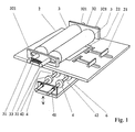
- the arrangement according to the invention for folding sheets consists of a sliding table 2 on which a pair of folding rollers 3 in bearings 32 and a stop 21 are adjustably arranged in slots, not specified.
- the bearings 32 are provided with elongated holes 321, in which the folding rollers 3 with their axes 31 are rotatably and displaceably held.
- Tension springs 33 tensioned between the axes 31 cause the folding rollers 3 to engage one another in a force-fitting manner or, adapted to folding material of different thicknesses, clamp the same between them.
- the sliding table 2 preferably takes a sloping position at an angle of 35 o ; for the sake of simplification not taken into account in the drawing.
- a pair of pressure rollers 4 are mounted on a lifting table 6 that can be adjusted parallel to the same.
- the lifting table 6 is positioned in relation to the sliding table 2 in such a way that the pressure rollers 4 lie axially symmetrical to the folding rollers 3.
- the pressure rollers 4 are subdivided in the axial direction, and a stop 21, also not shown, which is also subdivided, can be displaced into the gaps 42 between the axes 41.
- the diameter Db of the pressure rollers 4 is smaller than half the diameter Da of the folding rollers 3.
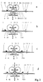
- Fig. 2 the sequence of a folding process is shown schematically with the arrangement according to the invention.
- a sheet 1 is moved on the sliding table 2 in the direction of the stop 21.
- the stop 21 is set accordingly to the arc length and the desired fold length.
- the stop 21 is flat in its part 211 adjacent to the sliding table 2.
- the more distant part 212 is concave, adapted to the curvature of the folding roller 3.
- the lifting table 6 is initially lowered. In this case, sheet 1 should be folded in the middle. After the sheet 1 has reached the stop 21, the lifting table 6 is moved upwards until the pressure rollers 4 press the sheet 1 against the folding rollers 3, see FIGS. 2b and 2c.
- the sheet 1 Due to the smaller diameter of the pressure rollers 4, the sheet 1 is pre-oriented in the direction of the folding rollers 3 before the clamping action occurs between the pressure rollers 4 and the folding rollers 3.
- the sheet 1 is pressed into the area between the folding rollers 3, gripped by them, folded and pushed on.
- the folding rollers 3 are automatically pushed apart by the double sheet thickness against the spring force of the tension spring 33.
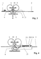
- Fig. 3 the sequence is shown when the sheet 1 passes the folding rollers 3 unfolded.
- the sheet 1 is moved on the sliding table 2 up to the vicinity of the area between the first folding roller 3 and the first pressure roller 4 and at the same time the lifting table 6 is moved upwards.
- the stop 21 is adjusted into the area between the folding rollers 3.
- the sheet 1 can assume the position in front of or between the pair of rollers 3, 4; that depends entirely on the control of the movement.
- the sheet 1 meets the concave flank 212 of the stop 21 and is guided by this between the folding rollers 3.
- the folding rollers 3 grip the sheet 1 and move it smoothly.
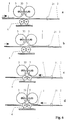
- Fig. 4 the adjustment options of the stop 21 are shown by means of a slot guide not specified.
- Fig. 5 the movement sequence "smooth passage” is illustrated without stop adjustment.
- the sheet 1 runs on the sliding table 2 up to the first pair of rollers 3, 4, is moved further by this, meets with its end edge on the second folding roller 3 and is deflected by this into the folding area and passes through it, see FIGS. 5b and 5c.
- Fig. 6 the sequence of movements of the function "turning and smooth passage" is shown.
- the sheet 1 passes the area between the pressure and folding rollers 4, 3 until the stop 21 is reached, see FIGS. 6a and 6b.
- the lifting table 6 assumes the lower, distant position.
- the stop 21 is set so that the adjacent sheet 1 is located with its rear part between the second pressure roller 4 and the second folding roller 3. If the lifting table 6 is moved upwards, the rear part of the sheet 1 is clamped between the rollers mentioned and guided in the direction of the first folding roller 3, deflected by the latter between the folding rollers 3 through which the sheet 2 thus turned passes smoothly, see FIG. 6c and 6d.
- guide rollers 9, which are still driving, are provided on both sides in parallel and in parallel with the folding rollers 3. Assigned to the guide rollers 9 are on a corresponding widened lifting table 6 additional pressure rollers stored. This arrangement is intended for safe guidance for particularly short folded goods or short sheets that are not to be folded.
- FIG. 9 shows an alternative to a resilient mounting of the folding rollers 3.
- the folding rollers 3 are mounted with their axes 31 in pivotable bearings 32 designed as rotatable levers, between which a tension spring 33 is tensioned.
- the bearings 32 are in turn fastened with their axis 322 in bearing blocks 34 so that they can move.
Landscapes
- Engineering & Computer Science (AREA)
- Mechanical Engineering (AREA)
- Folding Of Thin Sheet-Like Materials, Special Discharging Devices, And Others (AREA)
Applications Claiming Priority (2)
| Application Number | Priority Date | Filing Date | Title |
|---|---|---|---|
| DE19611788 | 1996-03-12 | ||
| DE19611788A DE19611788C2 (de) | 1996-03-12 | 1996-03-12 | Anordnung zum Falzen von Bögen |
Publications (3)
| Publication Number | Publication Date |
|---|---|
| EP0795507A2 true EP0795507A2 (fr) | 1997-09-17 |
| EP0795507A3 EP0795507A3 (fr) | 1998-07-08 |
| EP0795507B1 EP0795507B1 (fr) | 2001-10-17 |
Family
ID=7789378
Family Applications (1)
| Application Number | Title | Priority Date | Filing Date |
|---|---|---|---|
| EP97101699A Expired - Lifetime EP0795507B1 (fr) | 1996-03-12 | 1997-02-04 | Dispositif pour plier des feuilles |
Country Status (3)
| Country | Link |
|---|---|
| US (1) | US6042529A (fr) |
| EP (1) | EP0795507B1 (fr) |
| DE (2) | DE19611788C2 (fr) |
Cited By (1)
| Publication number | Priority date | Publication date | Assignee | Title |
|---|---|---|---|---|
| FR3012066A1 (fr) * | 2013-10-21 | 2015-04-24 | Nmc Company | Module de pliage pour machine de fabrication de plis courriers et machine obtenue |
Families Citing this family (13)
| Publication number | Priority date | Publication date | Assignee | Title |
|---|---|---|---|---|
| US6939284B2 (en) * | 2001-10-05 | 2005-09-06 | Hewlett-Packard Development Company, L.P. | Sheet folding apparatus with rounded fold blade |
| US7052005B2 (en) * | 2002-06-07 | 2006-05-30 | Konica Corporation | Sheet postprocessing apparatus for use with image forming apparatus and folding method |
| US6773388B2 (en) * | 2002-06-28 | 2004-08-10 | Pitney Bowes Inc. | Folder apparatus with transverse loading |
| SE523007C2 (sv) * | 2002-07-04 | 2004-03-23 | Plockmatic Int Ab | Valsanordning vid häft- och falsmaskin |
| US6905118B2 (en) * | 2002-07-31 | 2005-06-14 | Ricoh Company, Ltd. | Sheet finisher and image forming system using the same |
| US20040127845A1 (en) * | 2002-12-27 | 2004-07-01 | Playtex Products, Inc. | Breast pump system |
| US6939283B2 (en) * | 2003-08-12 | 2005-09-06 | Xerox Corporation | Booklet maker with flexible gate upstream of crease rolls |
| DE102004012930B4 (de) * | 2004-03-17 | 2007-04-05 | Man Roland Druckmaschinen Ag | Druckmaschine mit einer Vorrichtung zum Messen eines zu falzenden Druckproduktes |
| AT500981B1 (de) * | 2004-11-02 | 2006-10-15 | Zechner Karl | Stauchfalzmaschine |
| JP2009029523A (ja) * | 2007-07-24 | 2009-02-12 | Toshiba Corp | 折り処理装置とこれを備えた装置、及び折り処理方法 |
| US7537556B2 (en) * | 2007-10-25 | 2009-05-26 | Xerox Corporation | High capacity knife folding system |
| JP2010275111A (ja) * | 2009-04-27 | 2010-12-09 | Ricoh Co Ltd | 用紙処理装置、及び画像形成装置 |
| ITUB20155074A1 (it) * | 2015-10-23 | 2017-04-23 | Ima Spa | Apparato piegatore e relativo procedimento |
Citations (6)
| Publication number | Priority date | Publication date | Assignee | Title |
|---|---|---|---|---|
| DE4018709A1 (de) | 1989-06-30 | 1991-01-10 | Polygraph Brehmer Leipzig Veb | Einstelleinrichtung fuer falzmesser und falzwalzen |
| DE4012859C2 (de) | 1990-04-23 | 1993-12-16 | Baeuerle Gmbh Mathias | Stauchfalzmaschine mit Beilagenzuführeinrichtung |
| EP0583587A1 (fr) | 1992-08-17 | 1994-02-23 | Mathias Bäuerle GmbH | Machine de pliage à poches |
| EP0595105A1 (fr) | 1992-10-28 | 1994-05-04 | Mathias Bäuerle GmbH | Plieuse à poches avec rouleaux réglables ou mobiles |
| DE4324199C1 (de) | 1993-07-19 | 1994-09-15 | Binder & Co Masch Oppenweiler | Vorrichtung zur symmetrischen Verstellung eines Falzwalzenspaltes in einem Schwertfalzwerk |
| EP0641733A1 (fr) | 1993-09-02 | 1995-03-08 | MBO MASCHINENBAU OPPENWEILER BINDER GMBH & CO. | Plieuse à poches |
Family Cites Families (14)
| Publication number | Priority date | Publication date | Assignee | Title |
|---|---|---|---|---|
| DE101875C (fr) * | ||||
| GB727920A (en) * | 1951-11-14 | 1955-04-13 | Chemstrand Corp | Device for directing a running length of flexible material into a feeding mechanism |
| DD101875A1 (fr) * | 1972-12-15 | 1973-11-20 | ||
| CH623289A5 (fr) * | 1977-10-24 | 1981-05-29 | Ferag Ag | |
| DE2912839A1 (de) * | 1979-03-30 | 1980-10-16 | Meteor Siegen Apparat Schmeck | Vorrichtung zum falzen von bogen aus papier o.dgl. |
| EP0038942B1 (fr) * | 1980-04-30 | 1985-06-26 | ERNST NAGEL GmbH & Co. KG | Machine à plier et à brocher des feuilles de papier |
| EP0059357B1 (fr) * | 1981-02-26 | 1985-09-25 | Hasler AG | Plieuse |
| SU1050892A1 (ru) * | 1982-06-17 | 1983-10-30 | Омский политехнический институт | Устройство дл фальцовки бумажных листов |
| US4643705A (en) * | 1985-07-29 | 1987-02-17 | Xerox Corporation | Positive drive knife folder |
| US4824426A (en) * | 1987-05-11 | 1989-04-25 | Paper Converting Machine Company | Method and apparatus for interfolding webs |
| US4898570A (en) * | 1987-09-14 | 1990-02-06 | Pitney Bowes | Method and apparatus for half folding paper sheets |
| JP2634262B2 (ja) * | 1989-12-01 | 1997-07-23 | 三菱重工業株式会社 | 紙ガイド装置 |
| DE4101399A1 (de) * | 1991-01-18 | 1992-07-23 | Kodak Ag | Vorrichtung zum falten von blaettern |
| DE19543152C2 (de) * | 1995-11-18 | 1999-09-02 | Kodak Ag | Vorrichtung zum Falten von Blättern |
-
1996
- 1996-03-12 DE DE19611788A patent/DE19611788C2/de not_active Expired - Fee Related
-
1997
- 1997-02-04 DE DE59704916T patent/DE59704916D1/de not_active Expired - Fee Related
- 1997-02-04 EP EP97101699A patent/EP0795507B1/fr not_active Expired - Lifetime
- 1997-03-12 US US08/815,207 patent/US6042529A/en not_active Expired - Fee Related
Patent Citations (6)
| Publication number | Priority date | Publication date | Assignee | Title |
|---|---|---|---|---|
| DE4018709A1 (de) | 1989-06-30 | 1991-01-10 | Polygraph Brehmer Leipzig Veb | Einstelleinrichtung fuer falzmesser und falzwalzen |
| DE4012859C2 (de) | 1990-04-23 | 1993-12-16 | Baeuerle Gmbh Mathias | Stauchfalzmaschine mit Beilagenzuführeinrichtung |
| EP0583587A1 (fr) | 1992-08-17 | 1994-02-23 | Mathias Bäuerle GmbH | Machine de pliage à poches |
| EP0595105A1 (fr) | 1992-10-28 | 1994-05-04 | Mathias Bäuerle GmbH | Plieuse à poches avec rouleaux réglables ou mobiles |
| DE4324199C1 (de) | 1993-07-19 | 1994-09-15 | Binder & Co Masch Oppenweiler | Vorrichtung zur symmetrischen Verstellung eines Falzwalzenspaltes in einem Schwertfalzwerk |
| EP0641733A1 (fr) | 1993-09-02 | 1995-03-08 | MBO MASCHINENBAU OPPENWEILER BINDER GMBH & CO. | Plieuse à poches |
Cited By (2)
| Publication number | Priority date | Publication date | Assignee | Title |
|---|---|---|---|---|
| FR3012066A1 (fr) * | 2013-10-21 | 2015-04-24 | Nmc Company | Module de pliage pour machine de fabrication de plis courriers et machine obtenue |
| WO2015059543A1 (fr) | 2013-10-21 | 2015-04-30 | Nmc Company | Module de pliage pour machine de fabrication de plis courriers et machine obtenue |
Also Published As
| Publication number | Publication date |
|---|---|
| US6042529A (en) | 2000-03-28 |
| DE19611788A1 (de) | 1997-09-18 |
| EP0795507B1 (fr) | 2001-10-17 |
| EP0795507A3 (fr) | 1998-07-08 |
| DE59704916D1 (de) | 2001-11-22 |
| DE19611788C2 (de) | 1999-11-11 |
Similar Documents
| Publication | Publication Date | Title |
|---|---|---|
| EP0883566B1 (fr) | Plieuse a lames | |
| EP0795507B1 (fr) | Dispositif pour plier des feuilles | |
| DD276175A5 (de) | Sortier- und stapelvorrichtung fuer wertscheine, insbesondere banknoten | |
| EP0735979B1 (fr) | Procede et dispositif permettant de fa onner un pli longitudinal | |
| EP3533609B1 (fr) | Dispositif et procédé de traitement ultérieur séquentiel de feuilles imprimées | |
| DE68909706T2 (de) | Vorrichtung zum Öffnen und Füllen von Briefumschlägen. | |
| DE68914686T2 (de) | Vorrichtung zum ablegen von kopieblättern. | |
| EP0888242B1 (fr) | Dispositif de changement de la direction d'acheminement de feuilles individuelles | |
| EP0167982A2 (fr) | Plieuse à poches comportant un dispositif pour réguler le courant d'articles pliés | |
| DE19611787C2 (de) | Anordnung zum Falzen von Bögen | |
| EP2319788B1 (fr) | Plieuse dotée d'un dispositif d'extraction | |
| EP1112952B1 (fr) | Dispositif pour plier en continu de matériau plat | |
| DE2434360A1 (de) | Vorrichtung zum stapeln loser papierboegen | |
| DE4207069C2 (de) | Vorrichtung zum Leiten von Blättern auf eine Ablagefläche | |
| DE10203176A1 (de) | Vorrichtung zur Entgegennahme von gebündelten Scheinen wie Banknoten oder Scheckformularen | |
| EP1247775B1 (fr) | Plieuse pour les produits imprimés | |
| EP0322398B1 (fr) | Dispositif de pliage | |
| EP0418456B1 (fr) | Dispositif pour le guidage de feuilles en mouvement ainsi que son utilisation | |
| DE2301172C2 (de) | Faltmaschine | |
| DE3616804A1 (de) | Blattvereinzelungsvorrichtung | |
| EP1270481A2 (fr) | Dispositif pour le pliage de feuilles de papier, plastique ou similaire | |
| WO2006133936A1 (fr) | Systeme pour traiter des documents de valeur en forme de feuille | |
| DE29601452U1 (de) | Stapelvorrichtung für kartenförmige Güter | |
| EP1930262B1 (fr) | Dispositif destinés à ouvrir et aérer des piles de matériau constituées de feuilles | |
| DE1611360C3 (de) | Falztasche |
Legal Events
| Date | Code | Title | Description |
|---|---|---|---|
| PUAI | Public reference made under article 153(3) epc to a published international application that has entered the european phase |
Free format text: ORIGINAL CODE: 0009012 |
|
| AK | Designated contracting states |
Kind code of ref document: A2 Designated state(s): CH DE FR GB IT LI |
|
| PUAL | Search report despatched |
Free format text: ORIGINAL CODE: 0009013 |
|
| AK | Designated contracting states |
Kind code of ref document: A3 Designated state(s): CH DE FR GB IT LI |
|
| 17P | Request for examination filed |
Effective date: 19980917 |
|
| GRAG | Despatch of communication of intention to grant |
Free format text: ORIGINAL CODE: EPIDOS AGRA |
|
| GRAG | Despatch of communication of intention to grant |
Free format text: ORIGINAL CODE: EPIDOS AGRA |
|
| GRAH | Despatch of communication of intention to grant a patent |
Free format text: ORIGINAL CODE: EPIDOS IGRA |
|
| 17Q | First examination report despatched |
Effective date: 20001218 |
|
| GRAH | Despatch of communication of intention to grant a patent |
Free format text: ORIGINAL CODE: EPIDOS IGRA |
|
| GRAA | (expected) grant |
Free format text: ORIGINAL CODE: 0009210 |
|
| AK | Designated contracting states |
Kind code of ref document: B1 Designated state(s): CH DE FR GB IT LI |
|
| REG | Reference to a national code |
Ref country code: CH Ref legal event code: NV Representative=s name: ROTTMANN, ZIMMERMANN + PARTNER AG Ref country code: CH Ref legal event code: EP |
|
| REF | Corresponds to: |
Ref document number: 59704916 Country of ref document: DE Date of ref document: 20011122 |
|
| ET | Fr: translation filed | ||
| REG | Reference to a national code |
Ref country code: GB Ref legal event code: IF02 |
|
| PGFP | Annual fee paid to national office [announced via postgrant information from national office to epo] |
Ref country code: GB Payment date: 20020118 Year of fee payment: 6 |
|
| PGFP | Annual fee paid to national office [announced via postgrant information from national office to epo] |
Ref country code: DE Payment date: 20020123 Year of fee payment: 6 |
|
| PGFP | Annual fee paid to national office [announced via postgrant information from national office to epo] |
Ref country code: FR Payment date: 20020124 Year of fee payment: 6 |
|
| PGFP | Annual fee paid to national office [announced via postgrant information from national office to epo] |
Ref country code: CH Payment date: 20020130 Year of fee payment: 6 |
|
| GBT | Gb: translation of ep patent filed (gb section 77(6)(a)/1977) |
Effective date: 20020117 |
|
| RAP2 | Party data changed (patent owner data changed or rights of a patent transferred) |
Owner name: FRANCOTYP-POSTALIA AG & CO. KG |
|
| PLBE | No opposition filed within time limit |
Free format text: ORIGINAL CODE: 0009261 |
|
| STAA | Information on the status of an ep patent application or granted ep patent |
Free format text: STATUS: NO OPPOSITION FILED WITHIN TIME LIMIT |
|
| 26N | No opposition filed | ||
| PG25 | Lapsed in a contracting state [announced via postgrant information from national office to epo] |
Ref country code: GB Free format text: LAPSE BECAUSE OF NON-PAYMENT OF DUE FEES Effective date: 20030204 |
|
| PG25 | Lapsed in a contracting state [announced via postgrant information from national office to epo] |
Ref country code: LI Free format text: LAPSE BECAUSE OF NON-PAYMENT OF DUE FEES Effective date: 20030228 Ref country code: CH Free format text: LAPSE BECAUSE OF NON-PAYMENT OF DUE FEES Effective date: 20030228 |
|
| PG25 | Lapsed in a contracting state [announced via postgrant information from national office to epo] |
Ref country code: DE Free format text: LAPSE BECAUSE OF NON-PAYMENT OF DUE FEES Effective date: 20030902 |
|
| GBPC | Gb: european patent ceased through non-payment of renewal fee | ||
| REG | Reference to a national code |
Ref country code: CH Ref legal event code: PL |
|
| PG25 | Lapsed in a contracting state [announced via postgrant information from national office to epo] |
Ref country code: FR Free format text: LAPSE BECAUSE OF NON-PAYMENT OF DUE FEES Effective date: 20031031 |
|
| REG | Reference to a national code |
Ref country code: FR Ref legal event code: ST |
|
| PG25 | Lapsed in a contracting state [announced via postgrant information from national office to epo] |
Ref country code: IT Free format text: LAPSE BECAUSE OF NON-PAYMENT OF DUE FEES;WARNING: LAPSES OF ITALIAN PATENTS WITH EFFECTIVE DATE BEFORE 2007 MAY HAVE OCCURRED AT ANY TIME BEFORE 2007. THE CORRECT EFFECTIVE DATE MAY BE DIFFERENT FROM THE ONE RECORDED. Effective date: 20050204 |