EP0797237A2 - Flache kompakte Fluoreszenzlampe - Google Patents
Flache kompakte Fluoreszenzlampe Download PDFInfo
- Publication number
- EP0797237A2 EP0797237A2 EP97104533A EP97104533A EP0797237A2 EP 0797237 A2 EP0797237 A2 EP 0797237A2 EP 97104533 A EP97104533 A EP 97104533A EP 97104533 A EP97104533 A EP 97104533A EP 0797237 A2 EP0797237 A2 EP 0797237A2
- Authority
- EP
- European Patent Office
- Prior art keywords
- channel
- phosphor
- coating
- lamp
- front panel
- Prior art date
- Legal status (The legal status is an assumption and is not a legal conclusion. Google has not performed a legal analysis and makes no representation as to the accuracy of the status listed.)
- Granted
Links
Images



Classifications
-
- H—ELECTRICITY
- H01—ELECTRIC ELEMENTS
- H01J—ELECTRIC DISCHARGE TUBES OR DISCHARGE LAMPS
- H01J61/00—Gas-discharge or vapour-discharge lamps
- H01J61/02—Details
- H01J61/38—Devices for influencing the colour or wavelength of the light
- H01J61/42—Devices for influencing the colour or wavelength of the light by transforming the wavelength of the light by luminescence
-
- H—ELECTRICITY
- H01—ELECTRIC ELEMENTS
- H01J—ELECTRIC DISCHARGE TUBES OR DISCHARGE LAMPS
- H01J61/00—Gas-discharge or vapour-discharge lamps
- H01J61/02—Details
- H01J61/30—Vessels; Containers
- H01J61/305—Flat vessels or containers
- H01J61/307—Flat vessels or containers with folded elongated discharge path
-
- Y—GENERAL TAGGING OF NEW TECHNOLOGICAL DEVELOPMENTS; GENERAL TAGGING OF CROSS-SECTIONAL TECHNOLOGIES SPANNING OVER SEVERAL SECTIONS OF THE IPC; TECHNICAL SUBJECTS COVERED BY FORMER USPC CROSS-REFERENCE ART COLLECTIONS [XRACs] AND DIGESTS
- Y02—TECHNOLOGIES OR APPLICATIONS FOR MITIGATION OR ADAPTATION AGAINST CLIMATE CHANGE
- Y02B—CLIMATE CHANGE MITIGATION TECHNOLOGIES RELATED TO BUILDINGS, e.g. HOUSING, HOUSE APPLIANCES OR RELATED END-USER APPLICATIONS
- Y02B20/00—Energy efficient lighting technologies, e.g. halogen lamps or gas discharge lamps
Definitions
- the present invention relates to improvements in substantially flat compact fluorescent lamps, and especially to fluorescent lamps having at least one convoluted channel formed by convoluted partition disposed between a pair of substantially flat panels.
- the channel is molded as one part of one of the panels and forms an integral part of the panel.
- the other panel is sealed to the periphery of the partition forming the channel to form an envelope.
- Conventional fluorescent lamps have an elongated tubular envelope construction with electrodes disposed at either end. When a potential is imposed upon the electrodes, mercury ions and excited mercury atoms form and produce ultraviolet light which in turn excites a phosphor coating to emit visible light.
- a recent improvement in fluorescent lamps is a so-called compact fluorescent lamp.
- Such compact fluorescent lamps are fabricated by bending a tubular glass envelope into a U-shape, or even bending it several times to form quadruple U-shapes. Since the brightness of the fluorescent lamp is dependent upon the length of the envelope, such complex bending operations are necessary to obtain a high light output. Even with complex bending, the compact fluorescent lamps tend to be rather long and require external fixtures, especially when they are employed for uses which require directionality.
- compact fluorescent lamps can operate at excessively high temperatures which produce high mercury vapor pressures beyond the optimum value needed for maximum lumen efficiency. Such high operating temperatures can also reduce the life of the components of the lamp.
- Lamps in the form of flat panels with channels in them are well known to the art.
- U.S Patent to Polevitzky, No. 2,405,5108 discloses a molded cup formed of a ceramic, plastic or stamped metal.
- a spiral partition is disposed within the cup and electrodes are placed at each end of the spiral partition.
- a glass cover or top panel is disposed over the face of the chamber formed by the cup and is hermetically sealed to a flange to provide a closure.
- Other patents related to flat fluorescent lamps include the U.S. Patent to Holmes, No. 2,406,146, wherein a fluorescent lamp with a spiral channel discharge is disclosed.
- an opposing spiral channel discharge is disclosed.
- the Krefft patent, U.S. Patent 2,555,749, alto discloses a channel fluorescent lamp.
- the U.S. Patent to Martyny, No. 3,247,415 discloses a fluorescent panel lamp in which internal partitions were pressed with low pressure under heat.
- U.S. Patent to Scott, No. 3,258,630 discloses a channel discharge lamp with a sinuous path.
- the present invention relates to substantially flat compact fluorescent lamps, and especially to fluorescent lamps having at least one convoluted channel formed by a convoluted partition disposed between a pair of substantially flat panels.
- the channel is molded into one of the panels and forms an integral part of the panel.
- the other panel is sealed at the periphery of the partition forming the channel to form an envelope.
- UV radiation which is produced inside the tube goes in all directions with equal probability.
- the phosphor should be placed on the inner walls of the tubes in uniform thickness. The amount of phosphor coating is carefully optimized because if the phosphor coating is too thin then all UV photons will not be effectively utilized, thereby reducing the efficiency of the lamp. On the other hand, if the phosphor coating is too thick the visible radiation generated by the innermost portion of the phosphor layer will be absorbed by the portion of the layer adjacent the glass of the envelope, thereby reducing the efficiency of the lamp. At the same time the cost of the lamp is increased because of an excessive amount of phosphor.
- the present invention relates to a flat compact fluorescent lamp which contains a fill of mercury and an inert gas.
- the lamp includes a front panel and a bottom molded part, including a bottom panel with an integral convoluted glass partition disposed between the front and the bottom panel.
- the partition is arranged as a convoluted channel, preferably in a spiral shape with a substantially uniform width throughout its length.
- a phosphor coating of predetermined density is disposed on the front panel and another phosphor coating, also or predetermined density, is disposed on the convoluted channel.
- the density of the phosphor coating on the front panel is significantly less than the density of the coating on the convoluted channel.
- the predetermined density of the phosphor coating on the channel is between about 3 and 5mg/cm 2
- the predetermined density of the phosphor on the inner surface of the front panel is between about 0.5 and 1.5mg/cm 2 .
- the edge of the partition abutting the inner surface of the front panel can be seen through the front panel as a spirally-shaped dark area. Since it is necessary for the width of the edges of the partition to be between 2 and 3mm to prevent the arc within one channel from arcing across to an adjacent channel, these darker areas will be visible. Reduction of the dark areas is important. We have also found that if the inner surface of the top panel is either sandblasted or coated with a silica film (or both of these techniques), the observability of the dark areas can be reduced. Thus, the lamp has an appearance of being all white and of uniform intensity wherein the channels and electrodes will not be visible from the outside of the lamp.
- the invention relates to a flat compact fluorescent lamp wherein the configuration of the convoluted channel is designed to take advantage of the low operating voltage of the lamp whilst preventing the formation of dark areas in certain regions of the lamp.
- the region not occupied by a discharge are cooler than the regions which are occupied and the cooler regions start to accumulate mercury and mercuric compounds during operation of the lamp which produces a non-uniform intensity of light.
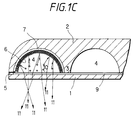
- Figures 1A, 1B, 1C are fragmentary cross-sectional views or a flat compact fluorescent lamp showing different density distributions of phosphor on the inner surface of the front panels of the lamps.
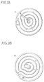
- Figures 2A, 2B and 2C are different embodiments of the shape of the concentric partitions forming the channels.
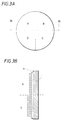
- Figure 3A is a front view of a compact flat fluorescent lamp divided into four quadrants which are coated with different densities of fluorescent material.
- Figure 3B is a cross-sectional view taken along the line 3B-3B of Figure 3A.
- Figure 3C is a curve showing the luminosity in each of the quadrants of the lamp in Figure 3A and comparing luminosity to phosphor surface density.
- phosphor coating densities in the order of 4mg/cm 2 of surface. Such coating densities are especially useful for tricalcium phosphate phosphors. They provide the maximum luminosity as a function of cost of the phosphor.
- the coverage on the inside of the fluorescent lamp is substantially uniform around the walls. As mentioned previously, in some applications a strip of the phosphor is removed. With such lamps it is conventional to place a reflective coating behind the phosphor such that the radiation passes through the slit and is directed on the work being illuminated.
- the lamp of the present invention is especially useful in down-light illumination.
- illumination from flat fluorescent lamps provides vary high brightness per unit surface area on the illuminated surface.
- the arc discharge goes from the periphery to the center or from one side of the periphery to the other side of the periphery depending upon the particular spiral configuration of the discharge which generates the UV photons.
- These UV photons have equal probability, as mentioned above, to be emitted in all the directions in any kind of a cross-sectional area of a lamp.
- the lamp has a front panel 1 and a bottom molded part 2 comprising a bottom panel and an integrally formed partition 3.
- the partition 3 forms channels 4.
- Front panel 3 is joined to the bottom molded part 2 by a frit seal 5 disposed on an outermost ring 3a.
- the partition 3 is integrally formed with the bottom molded part 2, however, in some cases the structure can be derived by sandwiching the convoluted partition 3 within two panels to form the channels 4 between them.
- the phosphor layer is shown only in the outermost portion of the channel 4, although it is to be understood all of the channel 4 is coated.
- a reflective coating 7 having a preferred surface density between about 6 and 9mg/cm 2 is disposed upon the interior of the channel 4 between the phosphor layer 6 and the walls of the channel 4.
- a protective, barrier layer 9 of aluminum oxide having a surface density between about 0.2 and 0.3mg/cm 2 is disposed upon the front panel 1 to prevent darkening of the interior of the panel by the amalgamation of mercury ions and components of the glass, such at soda lime.
- a photon of light is schematically represented at 10 as a circle with an arrowhead.
- the arrowhead depicts the direction of movement of the photon.
- some of the arrowheads are directed to the interior of the channel 4 where they will excite the phosphor 6 to produce light.
- some of the arrowheads are directed toward the front panel 1 where they will be absorbed by the glass and produce no visible radiation.
- photons which excite phosphors will cause the phosphor to emit visible light, as indicated by the straight arrows 11.
- FIG. 1B photons 10 again excite the phosphor 6 in the lamp.
- Figure 1B differs from Figure 1C in that there is a coating 8 of phosphor on the interior of the front panel 1.
- the density of the phosphor layer 8 on the front panel 1 in substantially the same as the density of the phosphor 6 on the channel 4.
- a UV photon excites the phosphor 6
- Some of the visible light that is emitted from the phosphor layer 6 encounters particles of the phosphor layer 8 and are reflected back to the phosphor layer 6. Some will be absorbed by the phosphor layer.
- a front surface of a compact fluorescent lamp is shown as divided into four quadrants (A, B, C, D).
- Quadrant A was covered with 1mg/cm 2 of phosphor
- quadrant B had 2mg/cm 2
- quadrant C had 3mg/cm 2
- quadrant D had 4mg/cm 2 .
- the phosphor layer (A and B) was laid over a thin, protective layer of aluminum oxide that was coated as a barrier layer on the inside surface of front plate 1.
- the measured luminosity is the light provided by both the phosphor coating on the channel plus light which is produced by the phosphor on the inner surface of the front panel.
- the phosphor coating on the channel was uniform throughout the lamp. Only the density of the phosphor on the inner surface of the front panel was varied.
- the density in quadrant D is equal to the density of phosphor disposed upon the channel, that is, a conventional density for a conventional fluorescent lamp.
- the results of the study are shown in Figure 3C in which quadrant A produced significantly more light per square meter than any of the other quadrants. Based on the trend of the curve, optimum coverage for the coating density on the lamp is between about 0.5 and 1.5mg/cm 2 .
- the lumen maintenance of the quadrant did not show any particular adverse effect because of the reduced coverage of the phosphor, especially when the inner surface of the front panel was first covered with the thin protective layer of fine particulate material, such as, aluminum oxide, titanium oxide, yttrium oxide, and similar oxides which are well known in the art, to form a barrier between the mercury ions and the glass. While such covering can produce a transmission loss when using a conventional particle size of less than about a micron, the transmission loss is less than about 1%. The covering, however, prevents amalgams from darkening the glass to reduce the effectiveness of the phosphor and to reduce the transmission of visible light. As can be seen with the results in quadrants B, C and D, the luminosity is significantly reduced as the density of the phosphor is increased.
- FIGS. 2A, 2B and 2C different embodiments of the shape of the spiral glass partition are shown.
- Each of the embodiments has an outer ring portion 3a.
- the rind portion 3a is used to seal the partition to the front panel 1 (not shown in this view).
- the frit used for sealing the components is placed upon the top of the circular outer ring portion 3a and fired to form a hermetically-sealed envelope.
- Electrodes 14a and 14b are disposed in wells in the lamp. Electrode 14a is centrally located in the lamp at the initial end of the channel 4 formed by the partition 3. Electrode 14b is disposed at the terminal end of the channel, adjacent ring 3a.
- the partition is exactly spirally-shaped, that is, the spacing between the various segments of the partition is identical, except where the partition 3 is adjacent to the outer ring portion 3a.
- the discharge does not hug the wall adjacent the outer ring portion 3a.
- the width of the channels is substantially uniform throughout the entire length of the spiral partition.
- Such uniform width is provided by narrowing the channel 4 between the electrode 14b and the section of the partition immediately adjacent it. In this way, the uniform spiral shape is distorted to maintain the uniform width of the channel 4.
- the spiral has significant sharp kinks. Such kinks, however, introduce high lamp voltages at the kinks at the locations indicated with arrowheads.
- any dark spirals due to the partitions can be further enhanced by sandblasting or depositing a silica film upon the inner surface of the front panel 1.
- the sandblasting or silica deposition (or both) or the inner surface of the front panel reduces the visibility or the channels and provides a more uniform light distribution.
- the light intensity with the flat compact fluorescent lamp of the present invention has bean found to be extremely bright. We found that glare from such a bright light source is better diffused with silica film and/or sandblasting, and results in a reasonably bright uniform radiation that is aesthetically pleasing.
- the lamp has a fairly uniform appearance across its surface during operation.
- a reduced density coverage of the inner surface of the front panel can be accomplished in a variety of ways, preferably a spray or a couple of drops of slurry can be dropped in the center of the front panel.
- the panel is spun at a high speed to provide uniform distribution of the droplets.
- Other manufacturing techniques for applying phosphors to the remainder of the lamp are well known in the art.
- a flat compact fluorescent lamp contains a fill of mercury and inert gas.
- the lamp includes a glass front panel (1) having on inner surface and a glass bottom penal (2) also having an inner surface.
- a convoluted glass partition (3) having an eccentric spiral shape and smooth bands is disposed between the inner surfaces of the front and bottom panels and with the bottom panel (2) defines a channel (4) in the lamp.
- the channel (4) has a fairly uniform width.
- a phosphor coating (6) of a predetermined density between about 3 and 5 mg./cm 2 is disposed on the inner surface of the channel (4) and a phosphor coating (8) of a predetermined density of between about 0.5 and 1.5 mg./cm 2 is disposed on the inner surface of the front panel (1).
- Two electrodes (14a & 14b) are disposed at opposite ends of the spiral in the lamp to form an arc which emits UV light to excite the phosphor (6 & 8) to emit light. Substantially all the light emerging from the phosphor 6 on the channel (4) passes through the thinner phosphor (8) coating on the front panel (1).
Landscapes
- Vessels And Coating Films For Discharge Lamps (AREA)
Applications Claiming Priority (2)
| Application Number | Priority Date | Filing Date | Title |
|---|---|---|---|
| US627905 | 1996-03-18 | ||
| US08/627,905 US5708324A (en) | 1996-03-18 | 1996-03-18 | Fluorescent lamp with different density phosphor coatings on the front panel and internal channels |
Publications (3)
| Publication Number | Publication Date |
|---|---|
| EP0797237A2 true EP0797237A2 (de) | 1997-09-24 |
| EP0797237A3 EP0797237A3 (de) | 1997-12-10 |
| EP0797237B1 EP0797237B1 (de) | 2002-01-02 |
Family
ID=24516636
Family Applications (1)
| Application Number | Title | Priority Date | Filing Date |
|---|---|---|---|
| EP97104533A Expired - Lifetime EP0797237B1 (de) | 1996-03-18 | 1997-03-17 | Flache kompakte Fluoreszenzlampe |
Country Status (4)
| Country | Link |
|---|---|
| US (1) | US5708324A (de) |
| EP (1) | EP0797237B1 (de) |
| JP (1) | JPH103883A (de) |
| DE (1) | DE69709423T2 (de) |
Cited By (1)
| Publication number | Priority date | Publication date | Assignee | Title |
|---|---|---|---|---|
| EP1659615A3 (de) * | 2004-05-29 | 2007-11-21 | Samsung Electronics Co., Ltd. | Flache lichterzeugende Vorrichtung und Anzeigevorrichtung mit derselben |
Families Citing this family (10)
| Publication number | Priority date | Publication date | Assignee | Title |
|---|---|---|---|---|
| WO2000026029A1 (en) * | 1998-11-04 | 2000-05-11 | Xenon Corporation | A spiral-shaped lamp for uv curing of coatings and bonding for a digital versatile disk (dvd) or compact disk (cd) |
| KR100362989B1 (ko) * | 2000-04-28 | 2002-11-29 | 주식회사 광운디스플레이기술 | 평판형 형광 램프 |
| JP2002083570A (ja) * | 2000-09-08 | 2002-03-22 | Sumitomo Chem Co Ltd | 真空紫外線励起発光素子 |
| KR100393190B1 (ko) * | 2001-03-06 | 2003-07-31 | 삼성전자주식회사 | 평판형광램프 제조방법 |
| US6747403B2 (en) * | 2001-08-22 | 2004-06-08 | Hewlett-Packard Development Company, L.P. | Lamp tube having a uniform lighting profile and a manufacturing method therefor |
| US7053555B2 (en) * | 2002-11-21 | 2006-05-30 | Matsushita Electric Industrial Co., Ltd. | Arc tube, discharge lamp, and production method of such arc tube, which enables brighter illuminance |
| JP2006085943A (ja) * | 2004-09-14 | 2006-03-30 | Matsushita Electric Ind Co Ltd | 発光管、蛍光ランプ及び照明装置 |
| US7462502B2 (en) * | 2004-11-12 | 2008-12-09 | Philips Lumileds Lighting Company, Llc | Color control by alteration of wavelength converting element |
| US8653732B2 (en) | 2007-12-06 | 2014-02-18 | General Electric Company | Ceramic metal halide lamp with oxygen content selected for high lumen maintenance |
| JP5759617B2 (ja) * | 2011-04-27 | 2015-08-05 | 振偉 ▲ミー▼ | 光学薄膜ランプ可視光線コーティングエリア出光構造を改善する装置 |
Family Cites Families (21)
| Publication number | Priority date | Publication date | Assignee | Title |
|---|---|---|---|---|
| US2446712A (en) * | 1942-04-13 | 1948-08-10 | Continental Electric Company | Lamp device |
| US2406146A (en) * | 1944-03-08 | 1946-08-20 | John E Holmes | Fluorescent lighting unit |
| FR922052A (fr) * | 1944-12-21 | 1947-05-28 | Gen Electric Co Ltd | Lampes électriques à décharge perfectionnées |
| US2405518A (en) * | 1945-11-14 | 1946-08-06 | Igor B Polevitzky | Illuminating device |
| US2555749A (en) * | 1947-12-17 | 1951-06-05 | Krefft Hermann Eduard | Fluorescent lamp |
| US3043983A (en) * | 1960-04-06 | 1962-07-10 | Sylvania Electric Prod | Electron discharge lamp |
| US3247415A (en) * | 1961-05-01 | 1966-04-19 | Gen Electric | Fluorescent panel lamp coating |
| US3258630A (en) * | 1962-02-09 | 1966-06-28 | Electric discharge lamps | |
| US3646383A (en) * | 1970-01-09 | 1972-02-29 | Gen Electric | Fluorescent panel lamp |
| JPS56143654A (en) * | 1980-04-08 | 1981-11-09 | Toshiba Corp | Fluorescent lamp |
| JPS62133663A (ja) * | 1985-12-04 | 1987-06-16 | Hitachi Ltd | 蛍光ランプ |
| US4839555A (en) * | 1986-05-13 | 1989-06-13 | Mahoney Patrick J O | Laminated lighting device |
| JPS63221550A (ja) * | 1987-03-09 | 1988-09-14 | Canon Inc | 蛍光灯 |
| JPH079796B2 (ja) * | 1987-03-28 | 1995-02-01 | 東芝ライテック株式会社 | 放電ランプ |
| AR244867A1 (es) * | 1987-11-27 | 1993-11-30 | Hartai Julius | Panel luminoso. |
| JPH03283344A (ja) * | 1990-03-30 | 1991-12-13 | Toshiba Lighting & Technol Corp | 金属蒸気放電ランプ |
| EP0449307B1 (de) * | 1990-03-30 | 1996-02-28 | Toshiba Lighting & Technology Corporation | Leuchtstofflampe und ihr Herstellungsverfahren |
| JPH076731A (ja) * | 1992-09-16 | 1995-01-10 | Sanyo Electric Co Ltd | フラット蛍光ランプ |
| JPH076732A (ja) * | 1993-06-21 | 1995-01-10 | Toshiba Lighting & Technol Corp | 屈曲形けい光ランプおよびこれを用いた照明器具 |
| HU217752B (hu) * | 1994-04-18 | 2000-04-28 | General Electric Co. | Elektród nélküli, fluoreszkáló reflektorlámpa |
| US5680005A (en) * | 1995-03-31 | 1997-10-21 | General Electric Company | Phosphor distribution for helical compact fluorescent lamp |
-
1996
- 1996-03-18 US US08/627,905 patent/US5708324A/en not_active Expired - Fee Related
-
1997
- 1997-03-17 EP EP97104533A patent/EP0797237B1/de not_active Expired - Lifetime
- 1997-03-17 DE DE69709423T patent/DE69709423T2/de not_active Expired - Fee Related
- 1997-03-18 JP JP9064852A patent/JPH103883A/ja active Pending
Cited By (1)
| Publication number | Priority date | Publication date | Assignee | Title |
|---|---|---|---|---|
| EP1659615A3 (de) * | 2004-05-29 | 2007-11-21 | Samsung Electronics Co., Ltd. | Flache lichterzeugende Vorrichtung und Anzeigevorrichtung mit derselben |
Also Published As
| Publication number | Publication date |
|---|---|
| EP0797237B1 (de) | 2002-01-02 |
| DE69709423T2 (de) | 2002-06-20 |
| DE69709423D1 (de) | 2002-02-07 |
| JPH103883A (ja) | 1998-01-06 |
| US5708324A (en) | 1998-01-13 |
| EP0797237A3 (de) | 1997-12-10 |
Similar Documents
| Publication | Publication Date | Title |
|---|---|---|
| US5708324A (en) | Fluorescent lamp with different density phosphor coatings on the front panel and internal channels | |
| US4546284A (en) | Low-pressure mercury vapor discharge lamp | |
| JPS6366025B2 (de) | ||
| US4393325A (en) | Low-pressure mercury vapor discharge lamp with mercury amalgam | |
| CN1022525C (zh) | 低压水银蒸汽放电灯 | |
| JP2005166638A (ja) | 冷陰極蛍光ランプおよび当該冷陰極蛍光ランプを搭載したバックライトユニット | |
| CA1081305A (en) | Low pressure gas discharge lamp with eccentrically located inner tube | |
| CN1118516A (zh) | 一种具有改进的荧光粉配置的无电极荧光灯及其制造方法 | |
| KR100372959B1 (ko) | 투영용금속할로겐화물가스방전램프 | |
| US6049164A (en) | Low-pressure mercury lamp with specific electrode screens | |
| US4069441A (en) | Electric gas discharge lamp having two superposed luminescent layers | |
| US4871942A (en) | Low-pressure discharge lamp | |
| JPS61185857A (ja) | 無電極放電灯 | |
| EP1063680A1 (de) | Leuchtstofflampe | |
| US20080203921A1 (en) | Single-ended Ceramic Discharge Lamp | |
| CA2336032A1 (en) | Dielectrically impeded discharge lamp with a spacer | |
| EP0907961B1 (de) | Niederdruckquecksilberentladungslampe | |
| JPH1050261A (ja) | 放電ランプ、照明装置、および表示装置 | |
| JP3374612B2 (ja) | 蛍光ランプの製造方法 | |
| JP3269105B2 (ja) | 照明装置 | |
| JPH04303548A (ja) | アパーチャ形けい光ランプ | |
| JPS60148043A (ja) | 金属蒸気放電灯 | |
| JP4257190B2 (ja) | 蛍光ランプ | |
| JPH10106502A (ja) | 蛍光ランプおよびこれを用いた表示装置 | |
| JPH0291682A (ja) | 発光素子 |
Legal Events
| Date | Code | Title | Description |
|---|---|---|---|
| PUAI | Public reference made under article 153(3) epc to a published international application that has entered the european phase |
Free format text: ORIGINAL CODE: 0009012 |
|
| AK | Designated contracting states |
Kind code of ref document: A2 Designated state(s): DE GB NL |
|
| PUAL | Search report despatched |
Free format text: ORIGINAL CODE: 0009013 |
|
| AK | Designated contracting states |
Kind code of ref document: A3 Designated state(s): DE GB NL |
|
| K1C3 | Correction of patent application (complete document) published |
Effective date: 19970924 |
|
| RAP1 | Party data changed (applicant data changed or rights of an application transferred) |
Owner name: MATSUSHITA ELECTRIC WORKS, LTD. |
|
| 17P | Request for examination filed |
Effective date: 19980212 |
|
| RAP1 | Party data changed (applicant data changed or rights of an application transferred) |
Owner name: MATSUSHITA ELECTRIC WORKS, LTD. |
|
| 17Q | First examination report despatched |
Effective date: 19991214 |
|
| GRAG | Despatch of communication of intention to grant |
Free format text: ORIGINAL CODE: EPIDOS AGRA |
|
| GRAG | Despatch of communication of intention to grant |
Free format text: ORIGINAL CODE: EPIDOS AGRA |
|
| GRAH | Despatch of communication of intention to grant a patent |
Free format text: ORIGINAL CODE: EPIDOS IGRA |
|
| GRAH | Despatch of communication of intention to grant a patent |
Free format text: ORIGINAL CODE: EPIDOS IGRA |
|
| GRAA | (expected) grant |
Free format text: ORIGINAL CODE: 0009210 |
|
| REG | Reference to a national code |
Ref country code: GB Ref legal event code: IF02 |
|
| AK | Designated contracting states |
Kind code of ref document: B1 Designated state(s): DE GB NL |
|
| REF | Corresponds to: |
Ref document number: 69709423 Country of ref document: DE Date of ref document: 20020207 |
|
| PLBE | No opposition filed within time limit |
Free format text: ORIGINAL CODE: 0009261 |
|
| STAA | Information on the status of an ep patent application or granted ep patent |
Free format text: STATUS: NO OPPOSITION FILED WITHIN TIME LIMIT |
|
| 26N | No opposition filed | ||
| PGFP | Annual fee paid to national office [announced via postgrant information from national office to epo] |
Ref country code: GB Payment date: 20070314 Year of fee payment: 11 |
|
| PGFP | Annual fee paid to national office [announced via postgrant information from national office to epo] |
Ref country code: NL Payment date: 20070315 Year of fee payment: 11 Ref country code: DE Payment date: 20070315 Year of fee payment: 11 |
|
| GBPC | Gb: european patent ceased through non-payment of renewal fee |
Effective date: 20080317 |
|
| PG25 | Lapsed in a contracting state [announced via postgrant information from national office to epo] |
Ref country code: NL Free format text: LAPSE BECAUSE OF NON-PAYMENT OF DUE FEES Effective date: 20081001 |
|
| NLV4 | Nl: lapsed or anulled due to non-payment of the annual fee |
Effective date: 20081001 |
|
| PG25 | Lapsed in a contracting state [announced via postgrant information from national office to epo] |
Ref country code: DE Free format text: LAPSE BECAUSE OF NON-PAYMENT OF DUE FEES Effective date: 20081001 |
|
| PG25 | Lapsed in a contracting state [announced via postgrant information from national office to epo] |
Ref country code: GB Free format text: LAPSE BECAUSE OF NON-PAYMENT OF DUE FEES Effective date: 20080317 |