EP0797376A2 - Elektrolumineszierende Anordnungen unter Verwendung von Blendsystemen - Google Patents
Elektrolumineszierende Anordnungen unter Verwendung von Blendsystemen Download PDFInfo
- Publication number
- EP0797376A2 EP0797376A2 EP97103671A EP97103671A EP0797376A2 EP 0797376 A2 EP0797376 A2 EP 0797376A2 EP 97103671 A EP97103671 A EP 97103671A EP 97103671 A EP97103671 A EP 97103671A EP 0797376 A2 EP0797376 A2 EP 0797376A2
- Authority
- EP
- European Patent Office
- Prior art keywords
- optionally substituted
- electroluminescent
- alkyl
- ring
- aryl
- Prior art date
- Legal status (The legal status is an assumption and is not a legal conclusion. Google has not performed a legal analysis and makes no representation as to the accuracy of the status listed.)
- Withdrawn
Links
Classifications
-
- C—CHEMISTRY; METALLURGY
- C09—DYES; PAINTS; POLISHES; NATURAL RESINS; ADHESIVES; COMPOSITIONS NOT OTHERWISE PROVIDED FOR; APPLICATIONS OF MATERIALS NOT OTHERWISE PROVIDED FOR
- C09K—MATERIALS FOR MISCELLANEOUS APPLICATIONS, NOT PROVIDED FOR ELSEWHERE
- C09K11/00—Luminescent materials, e.g. electroluminescent or chemiluminescent
- C09K11/06—Luminescent materials, e.g. electroluminescent or chemiluminescent containing organic luminescent materials
-
- H—ELECTRICITY
- H10—SEMICONDUCTOR DEVICES; ELECTRIC SOLID-STATE DEVICES NOT OTHERWISE PROVIDED FOR
- H10K—ORGANIC ELECTRIC SOLID-STATE DEVICES
- H10K85/00—Organic materials used in the body or electrodes of devices covered by this subclass
- H10K85/60—Organic compounds having low molecular weight
- H10K85/649—Aromatic compounds comprising a hetero atom
- H10K85/653—Aromatic compounds comprising a hetero atom comprising only oxygen as heteroatom
-
- C—CHEMISTRY; METALLURGY
- C09—DYES; PAINTS; POLISHES; NATURAL RESINS; ADHESIVES; COMPOSITIONS NOT OTHERWISE PROVIDED FOR; APPLICATIONS OF MATERIALS NOT OTHERWISE PROVIDED FOR
- C09B—ORGANIC DYES OR CLOSELY-RELATED COMPOUNDS FOR PRODUCING DYES, e.g. PIGMENTS; MORDANTS; LAKES
- C09B57/00—Other synthetic dyes of known constitution
- C09B57/02—Coumarine dyes
-
- H—ELECTRICITY
- H05—ELECTRIC TECHNIQUES NOT OTHERWISE PROVIDED FOR
- H05B—ELECTRIC HEATING; ELECTRIC LIGHT SOURCES NOT OTHERWISE PROVIDED FOR; CIRCUIT ARRANGEMENTS FOR ELECTRIC LIGHT SOURCES, IN GENERAL
- H05B33/00—Electroluminescent light sources
- H05B33/12—Light sources with substantially two-dimensional [2D] radiating surfaces
- H05B33/14—Light sources with substantially two-dimensional [2D] radiating surfaces characterised by the chemical or physical composition or the arrangement of the electroluminescent material, or by the simultaneous addition of the electroluminescent material in or onto the light source
-
- H—ELECTRICITY
- H10—SEMICONDUCTOR DEVICES; ELECTRIC SOLID-STATE DEVICES NOT OTHERWISE PROVIDED FOR
- H10K—ORGANIC ELECTRIC SOLID-STATE DEVICES
- H10K85/00—Organic materials used in the body or electrodes of devices covered by this subclass
- H10K85/60—Organic compounds having low molecular weight
- H10K85/649—Aromatic compounds comprising a hetero atom
- H10K85/654—Aromatic compounds comprising a hetero atom comprising only nitrogen as heteroatom
-
- H—ELECTRICITY
- H10—SEMICONDUCTOR DEVICES; ELECTRIC SOLID-STATE DEVICES NOT OTHERWISE PROVIDED FOR
- H10K—ORGANIC ELECTRIC SOLID-STATE DEVICES
- H10K85/00—Organic materials used in the body or electrodes of devices covered by this subclass
- H10K85/60—Organic compounds having low molecular weight
- H10K85/649—Aromatic compounds comprising a hetero atom
- H10K85/656—Aromatic compounds comprising a hetero atom comprising two or more different heteroatoms per ring
Definitions
- An electroluminescent (EL) arrangement is characterized in that it emits light when an electrical voltage is applied under current flow.
- LEDs light emitting diodes
- the emission of light occurs because positive charges ("holes”, holes) and negative charges (“electrons”, electrons) recombine while emitting light.
- inorganic semiconductors such as gallium arsenide are used today.
- Point-like display elements can be produced on the basis of such substances. Large-scale arrangements are not possible.
- electroluminescent arrangements based on evaporated low-molecular organic compounds are known (US Pat. No. 4,539,507, US Pat. No. 4,769,262, US Pat. No. 5,077,142, EP-A 406 762). With these materials too - due to the manufacturing process - only small-sized LEDs can be produced. In addition, these electroluminescent arrangements have very short lifetimes.
- Polymers such as poly (p-phenylene) and poly (p-phenylene vinylene (PPV)) are also described as electroluminescent polymers: G. Leising el al., Adv. Mater. 4 (1992) No. 1; Friend et al., J. Chem. Soc., Chem. Commun. 32 (1992); Saito et al., Polymer, 1990, Vol. 31, 1137; Friend et al., Physical Review B, Vol. 42, No. 18, 11670 or WO 90/13148. Further examples of PPV in electroluminescent displays are described in EP-A 443 861, WO-A-9203490 and 92003491.
- EP-A 0 294 061 presents an optical modulator based on polyacetylene.
- an EL arrangement consists of two electrodes, between which there is an organic layer that fulfills all functions - including the emission of light.
- organic layer that fulfills all functions - including the emission of light.
- a multilayer system can be built up by vapor deposition, in which the layers are applied successively from the gas phase, or by casting processes. Casting processes are preferred due to the higher process speeds. However, the dissolving process of a layer that has already been applied presents a difficulty when layering over with the next layer.
- the task is to provide blend systems based on fluorescent dyes and suitable binders for the construction of single and multilayer arrangements.
- fluorescent dyes of the general formulas (I) and (II) given below can be dispersed in transparent thermoplastics and processed into layer systems by casting processes.
- R 1 and R 8 meaning a 5- or 6-membered heterocyclic ring to which a benzene ring can be fused are: pyrazole, imidazole, thiazole, oxazole, 1,2,4-triazole, 1, 3,4-oxadiazole, 1,3,4-thiadiazole, benzimidazole, benzthiazole, benzoxazole, pyridine.
- Alkyl (R 5 , R 6 , R 7 , R 10 , R 11 and as a nonionic substituent of the 5- or 6-membered rings according to R 1 and R 8 ) preferably represents C 1 -C 6 alkyl.
- Alkenyl (R 5 , R 6 , R 7 , R 10 ) preferably represents C 2 -C 7 alkenyl, in particular allyl.
- Aryl (R 5 , R 6 , R 7 , R 11 and as a nonionic substituent of the 5- or 6-membered rings R 1 ) preferably represents phenyl.
- Cycloalkyl (R 5 , R 6 , R 7 , R 10 , R 11 and as a non-ionic substituent of the 5- or 6-membered rings according to R 1 and R 8 ) preferably represents C 3 -C 7 cycloalkyl, particularly preferably for cyclohexyl.
- Aralkyl (R 5 , R 6 , R 7 , R 10 , R 11 and as a nonionic substituent of the 5- or 6-membered rings R 1 ) preferably represents benzyl and phenethyl.
- Acyl (R 1 and R 8 ) preferably represents (C 1 -C 6 alkyl) carbonyl, benzoyl, C 1 -C 6 alkylsulfonyl and phenylsulfonyl.
- Halogen as a non-ionic substituent of the 5- or 6-membered rings according to R 1 and R 8 preferably represents chlorine, bromine and fluorine.
- Alkoxy as a non-ionogenic substituent of the 5- or 6-membered rings according to R 1 and R 8 preferably represents C 1 -C 6 alkoxy.
- Substituted alkyl (R 5 , R 6 , R 7 , R 10 , R 11 , R 4 ) stands for alkyl, for example by halogen such as chlorine and bromine, hydroxyl, cyano, trifluoromethyl, C 1 -C 6 alkoxy, C 1 -C 6 alkylsulfonyl, phenylsulfonyl, carbamoyl mono- and disubstituted by C 1 -C 6 alkyl and phenyl, sulfamoyl, mono- and disubstituted sulfamoyl by C 1 -C 6 alkyl and phenyl and by C 1 -C 6 phenyl mono- or disubstituted amino, may be substituted.
- halogen such as chlorine and bromine
- hydroxyl cyano
- trifluoromethyl C 1 -C 6 alkoxy
- C 1 -C 6 alkylsulfonyl
- Substituted aryl (R 5 , R 6 , R 7 , R 10 , R 11 , R 4 ) substituted cycloalkyl (R 2 and R 9 ) and substituted aralkyl (R 2 and R 9 ) represent aryl, cycloalkyl or aralkyl, (R 2 and R 9 ) represents aryl, cycloalkyl or aralkyl, which, in addition to the substituents mentioned above for alkyl, can also be substituted by C 1 -C 6 alkyl, for example.
- charge transport connections are understood to mean all connections which in some way transport holes and / or electrons. This also explicitly includes those compounds that are components of the emitter layer, i.e. represent photoluminescent materials, such as Fluorescent dyes or phenylamine derivatives or general tertiary amines.
- the photoluminescent dyes are dispersed in a soluble transparent binder.
- Soluble transparent polymers such as e.g. Polycarbonates, polystyrene and copolymers of polystyrene such as SAN, polysulfones, polymer based on monomers containing vinyl groups such as e.g. Polyacrylates, polyvinyl carbazole, polyvinyl pyrrolidone, vinyl acetate and vinyl alcohol polymers and copolymers, polyolefins, phenoxy resins, etc. are used.
- These inert binders can also be used as binders for the electron-conducting and / or hole-conducting materials.
- a comprehensive description of suitable polymeric binders is given in EP-A 532 798.
- the blends of the fluorescent dye and the inert binder stand out among others. characterized in that they are film-forming and can be applied to suitable substrates with a conductive layer by casting, knife coating or spin coating.
- a suitable combination of one or more fluorescent dyes and a transparent binder is set in a suitable solvent and the solution is applied to the transparent electrode by known methods - casting, knife coating, spin coating.
- This solution can be further added to substances, stabilizers effective against air, thermal oxidation, ozone and UV radiation, hole-conducting and / or electron-conducting compounds before the layer is produced.
- the hole-conducting substance which can be polymeric compounds, oligomers or monomers which are dispersed in a polymeric binder
- the transparent electrode is coated or vapor deposition processes.
- this layer is overlaid with the blend of fluorescent dye and binder.
- the electron-conducting layer can be applied separately to the light-emitting layer.
- the electron conductor which is a polymer or an oligomer dispersed in a binder or can act as monomers, dissolved in a suitable solvent and poured or evaporated onto the light-emitting layer.
- hole conductor and fluorescent dye in one blend and the electron conductor as a separate layer.
- a separate layer of a hole conductor can also be applied first, which is overlaid with a blend of fluorescent dye and electron conductor.
- the concentration of the fluorescent dye in the blend with the polymeric binder can be varied in the range from 2 to 85% by weight; the content is preferably 5 to 75% by weight, particularly preferably 10 to 70% by weight.
- the content of low molecular hole conductor in a polymeric binder can be varied in the range from 2 to 85% by weight; the content is preferably 5 to 75% by weight, particularly preferably 10 to 70% by weight.
- Film-forming hole conductors can also be used in pure form (100%).
- the content of low molecular weight electron conductors in polymeric binders can be varied in the range from 2 to 85% by weight; the content is preferably 5 to 75% by weight, particularly preferably 10 to 70% by weight.
- Film-forming electron conductors can also be used in pure form (100%).
- a transparent support e.g. Glass or plastic material, e.g. a film made of polyethylene terephthalate, polyethylene naphthalate, polycarbonate, polysulfone or polyimide is used.
- the metal oxide and semi-transparent metal film electrodes are applied in a thin layer using techniques such as vapor deposition, sputtering, platinum plating, etc.
- One of the electrodes is usually transparent in the visible spectral range.
- the thickness of the transparent electrode is 50 ⁇ to about several ⁇ m, preferably 100 ⁇ to 5000 ⁇ .
- the electroluminescent substance is applied directly to the transparent electrode or to a charge-transporting layer, if present, as a thin film.
- the thickness of the film is 30 ⁇ to 10 ⁇ m, preferably 50 ⁇ to 1 ⁇ m.
- a counter electrode This consists of a conductive substance that can be transparent.
- the arrangement according to the invention is brought into contact with the two electrodes by means of two electrical leads (e.g. metal wires).
- the arrangements emit light with a wavelength of 400 to 700 nm when a direct voltage is applied in the range up to 100 full. They show photoluminescence in the range from 400 to 700 nm.
- the blend systems according to the invention are distinguished by high quantum yields and low threshold voltages for electroluminescence. Different electroluminescent colors can be produced with them.
- blend systems according to the invention can be used in displays for lighting and for displaying information.
- the dyes Fb 1, Fb 2 and Fb 3 are used to build up the electroluminescent arrangements.
- the substrates are already supplied with sputtered transparent, conductive indium tin oxide (ITO). After cleaning the ITO surface with acetone and methanol, solutions of the polymeric materials are spun on with a spin coater from Hamatech, type HS 485, at defined speeds.
- ITO transparent, conductive indium tin oxide
- Low-molecular fluorescent dye Fb 1 (30% by weight) in the blend with the polymeric binder polyvinyl carbazole (PVC) (70% by weight). Both are in dichloroethane 0.5% solution and filtered with a 0.45 ⁇ m filter. After the solution has been pipetted onto the ITO anode, the substrate is rotated at a defined speed over a period of 30 seconds on the spin coater. The red blend films result in a layer thickness of 110 nm (at 500 rpm) or 35 nm (at 1000 rpm).
- Coumarin dye Fb 2 (30% by weight) in the blend with the polymeric binder polyvinyl carbazole (PVC) (70% by weight). Both are dissolved in 0.5% dichloroethane and filtered with a 0.45 ⁇ m filter.
- 500 and 1000 rpm on the spin coater result in layer thicknesses of the green blend films of 150 nm and 80 nm, respectively.
- Low-molecular fluorescent dye Fb 3 (30% by weight) in the blend with the polymeric binder polyvinyl carbazole (PVC) (70% by weight). Both are dissolved in 0.5% dichloroethane and filtered with a 0.45 ⁇ m filter. 500 or 1500 rpm set on the spin coater result in layer thicknesses of these blue blend films of 150 nm or 80 nm.
- the coated substrates are always temporarily stored in a vacuum oven at a pressure of 10 -3 mbar and a temperature of 50 ° C. in order to ensure that the solvents evaporate completely.
- the 2- (4-biphenyl) -5- (4-tert-butylphenyl) -1,3,4-oxadiazole (PBD) in the blend with polystyrene (PS) in a ratio of two parts is used as a polymer electron transport layer in a two-layer structure PBD and part PS used.
- the solution used for spin coating is 0.5% in ethyl acetate or in tetrahydrofuran (THF) and filtered with a 0.45 ⁇ m filter.
- This second layer in Multi-layer structure is spun on at 1500 rpm, which resulted in an additional thickness of approx. 40 nm.
- the cathode is applied in each case at a pressure of approximately 10 -7 mbar in a vapor deposition system from Leybold, Univex 450, aluminum (A1) being used as the cover electrode.
- the single-layer or two-layer PLEDs were characterized at computer-controlled measuring stations at which the diode characteristics, spectra of photoluminescence and electroluminescence were measured.
- Table 1 shows that different electroluminescent colors can be set with the blends according to the invention.
Landscapes
- Chemical & Material Sciences (AREA)
- Engineering & Computer Science (AREA)
- Materials Engineering (AREA)
- Physics & Mathematics (AREA)
- Spectroscopy & Molecular Physics (AREA)
- Organic Chemistry (AREA)
- Electroluminescent Light Sources (AREA)
- Luminescent Compositions (AREA)
Abstract
Gegenstand der Erfindung sind elektrolumineszierende Anordnungen, die mindestens 2 Elektroden, die Basiselektrode 2 und die Topelektrode 8 und eine die lichtemittierende Schicht 5, die einen Farbstoff der Formel (I) und/oder (II) enthält, enthalten: <IMAGE>
Description
- Eine elektrolumineszierende (EL) Anordnung ist dadurch charakterisiert, daß sie unter Anlegung einer elektrischen Spannung unter Stromfluß Licht aussendet. Derartige Anordnungen sind unter der Bezeichnung "Leuchtdioden" (LEDs = light emitting diodes) seit langem in der Technik bekannt. Die Emission von Licht kommt dadurch zustande, daß positive Ladungen ("Löcher", holes) und negative Ladungen ("Elektronen", electrons) unter Aussendung von Licht rekombinieren.
- Bei der Entwicklung lichtemittierender Bauteile für Elektronik oder Photonik kommen heute hauptsächlich anorganische Halbleiter, wie Galliumarsenid, zum Einsatz. Auf Basis derartiger Substanzen können punktförmige Anzeigeelemente hergestellt werden. Großflächige Anordnungen sind nicht möglich.
- Neben den Halbleiterleuchtdioden sind elektrolumineszierende Anordnungen auf Basis aufgedampfter niedermolekularer organischer Verbindungen bekannt (US-P 4 539 507, US-P 4 769 262, US-P 5 077 142, EP-A 406 762). Auch mit diesen Materialien können - bedingt durch das Herstellverfahren - nur kleindimensionierte LEDs hergestellt werden. Außerdem besitzen diese elektrolumineszierenden Anordnungen nur sehr geringe Lebensdauern.
- Weiterhin werden Polymere, wie Poly-(p-phenylene) und Poly-(p-phenylenvinylene (PPV)) als elektrolumineszierende Polymere beschrieben: G. Leising el al., Adv. Mater. 4 (1992) No. 1; Friend et al., J. Chem. Soc., Chem. Commun. 32 (1992); Saito et al., Polymer, 1990, Vol. 31, 1137; Friend et al., Physical Review B, Vol. 42, No. 18, 11670 oder WO 90/13148. Weitere Beispiele für PPV in Elektrolumineszenzanzeigen werden in EP-A 443 861, WO-A-9203490 und 92003491 beschrieben.
- EP-A 0 294 061 stellt einen optischen Modulator auf Basis von Polyacetylen vor.
- Zur Herstellung flexibler Polymer-LEDs haben Heeger at al. lösliche konjugierte PPV-Derivate vorgeschlagen (WO 92/16023).
- Polymerblends unterschiedlicher Zusammensetzung sind ebenfalls bekannt: M. Stolka et al., Pure & Appl. Chem., Vol. 67, No. 1, pp. 1775-182, 1995; H. Bässler et al., Adv. Mater. 1995, 7, No. 6, 551; K. Nagai et al., Appl. Phys. Lett. 67 (16), 1995, 2281; EP-A 532 798.
- Die organischen EL-Anordnungen enthalten in der Regel eine oder mehrere Schichten aus organischen Ladungstransportverbindungen. Der prinzipielle Aufbau in der Reihenfolge der Schichten ist wie folgt:
- 1
- Träger, Substrat
- 2
- Basiselektrode
- 3
- Löcher-injizierende Schicht
- 4
- Löcher-transportierende Schicht
- 5
- Licht-emittierende Schicht
- 6
- Elektronen-transportierende Schicht
- 7
- Elektronen-injizierende Schicht
- 8
- Topelektrode
- 9
- Kontakte
- 10
- Umhüllung, Verkapselung.
- Dieser Aufbau stellt den allgemeinsten Fall dar und kann vereinfacht werden, indem einzelne Schichten weggelassen werden, so daß eine Schicht mehrere Aufgaben übernimmt. Im einfachsten Fall besteht eine EL-Anordung aus zwei Elektroden, zwischen denen sich eine organische Schicht befindet, die alle Funktionen - inklusive der der Emission von Licht - erfüllt. Derartige Systeme sind z.B. in der Anmeldung WO 90/13148 auf der Basis von Poly-(p-phenylenvinylen) beschrieben.
- Der Aufbau von Mehrschichtsystem kann durch Aufdampfverfahren, bei denen die Schichten sukzessive aus der Gasphase aufgebracht werden oder durch Gießverfahren erfolgen. Gießverfahren sind aufgrund der höheren Prozeßgeschwindigkeiten bevorzugt. Allerdings stellt der Anlöseprozeß einer bereits aufgebrachten Schicht beim Überschichten mit der nächsten Schicht eine Schwierigkeit dar.
- Es besteht die Aufgabe, Blendsysteme auf Basis von Fluoreszenzfarbstoffen und geeigneten Bindern zum Aufbau von Ein- und Mehrschichtanordnungen bereitzustellen.
- Es wurde nun gefunden, daß Fluoreszenzfarbstoffe der unten angegebenen allgemeinen Formel (I) und (II) in transparenten Thermoplasten dispergiert und durch Gießverfahren zu Schichtsystemen verarbeitet werden können.
- Gegenstand der Erfindung sind elektrolumineszierende Anordnungen, die mindestens 2 Elektroden, die Basiselektrode 2 und die Topelektrode 8 und eine die lichtemittierende Schicht 5, die einen Farbstoff der Formel (I) und/oder (II) enthält, enthalten:

- T
- für Sauerstoff oder NR4 steht,
wobei - R4
- für Wasserstoff, gegebenenfalls substituiertes Alkyl oder gegebenenfalls substituiertes Aryl steht;
- R1 und R8
- ein über ein C-Atom gebundener carbo- oder heterocyclischer 5- oder 6-gliedriger Ring oder ein über ein N-Atom gebundener 5- oder 6-gliedriger heterocyclischer Ring bedeutet, der zu einer durch die Cumarin-N-Heterocyclus gelegten Achse rotationsunsymmetrisch ist, wobei die genannten 5- oder 6-gliedrigen Ringe nicht-ionogene Substituenten tragen können und an sie ein gegebenenfalls substituierter Benzol- oder ein gegebenenfalls substituierter Naphthalinring ankondensiert sein kann;
- R2 und R9
- gegebenenfalls substituiertes Alkyl, Alkenyl, gegebenenfalls substituiertes Cycloalkyl, gegebenenfalls substituiertes Aryl, gegebenenfalls substituiertes Aralkyl bedeutet oder für -O-R5 oder für
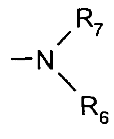
- R5, R6, R7 oder R10
- gleich oder verschieden sein können und für Wasserstoff, gegebenenfalls substituiertes Alkyl oder gegebenenfalls substituiertes Aryl stehen.
- R3
- für H oder CN sieht.
- R1 und R8
- stehen bevorzugt für einen 5- oder 6-gliedrigen heterocyclischen Ring, der 1, 2 oder 3 Heteroatome aus der Reihe N, O, S enthält und an den ein Benzolring ankondensiert sein kann, wobei sowohl der heterocyclische Ring wie auch der ankondensierte Benzolring durch beispielsweise Alkyl, Aryl, Aralkyl, Cycloalkyl, Halogen, Alkoxy, Cyan und Acyl substituiert sein können.
- Als Beispiele für R1 bzw. R8 in der Bedeutung eines 5- oder 6-gliedrigen heterocyclischen Ringes an den ein Benzolring ankondensiert sein kann, seien genannt: Pyrazol, Imidazol, Thiazol, Oxazol, 1,2,4-Triazol, 1,3,4-Oxadiazol, 1,3,4-Thiadiazol, Benzimidazol, Benzthiazol, Benzoxazol, Pyridin.
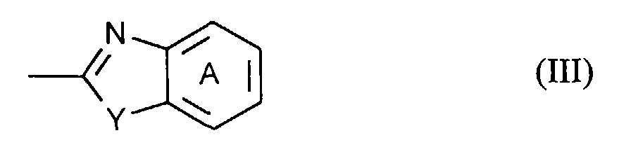
- Besonders bevorzugt stehen R1 und R8 für einen heterocyclischen Rest der Formel

- Y
- Sauerstoff, Schwefel oder NR11 bezeichnet, wobei
- R11
- für Wasserstoff, Alkyl, Aryl, Cycloalkyl oder Aralkyl sieht und der Ring A durch vorzugsweise 1 bis 2 Substituenten aus der Reihe C1-C4-Alkyl, C1-C4-Alkoxy, Brom, Chlor, Phenyl, Cyclohexyl, C1-C4-Alkylsulfonyl, Sulfamoyl oder C1-C4-Alkoxycarabonyl substituiert sein kann.
- Alkyl (R5, R6, R7, R10, R11 und als nicht-ionogener Substituent der 5- oder 6-gliedrigen Ringe gemäß R1 und R8) steht bevorzugt für C1-C6-Alkyl.
- Alkenyl (R5, R6, R7, R10) steht bevorzugt für C2-C7-Alkenyl, insbesondere Allyl.
- Aryl (R5, R6, R7, R11 und als nicht-ionogener Substituent der 5- oder 6-gliedrigen Ringe R1) steht bevorzugt für Phenyl.
- Cycloalkyl (R5, R6, R7, R10, R11 und als nicht-ionogener Substituent der 5- oder 6-gliedrigen Ringe gemäß R1 und R8) steht bevorzugt für C3-C7-Cycloalkyl, besonders bevorzugt für Cyclohexyl.
- Aralkyl (R5, R6, R7, R10, R11 und als nicht-ionogener Substituent der 5- oder 6-gliedrigen Ringe R1) steht bevorzugt für Benzyl und Phenethyl.
- Acyl (R1 und R8) steht bevorzugt für (C1-C6-Alkyl)-carbonyl, Benzoyl, C1-C6-Alkylsulfonyl und Phenylsulfonyl.
- Halogen als nicht-ionogener Substituent der 5- oder 6-gliedrigen Ringe gemäß R1 und R8 steht bevorzugt für Chlor, Brom und Fluor.
- Alkoxy als nicht-ionogener Substituent der 5- oder 6-gliedrigen Ringe gemäß R1 und R8 steht bevorzugt für C1-C6-Alkoxy.
- Substituiertes Alkyl (R5, R6, R7, R10, R11, R4) steht für Alkyl, das beispielsweise durch Halogen wie Chlor und Brom, Hydroxyl, Cyan, Trifluormethyl, C1-C6-Alkoxy, C1-C6-Alkylsulfonyl, Phenylsulfonyl, durch C1-C6-Alkyl und Phenyl mono- und disubstituiertes Carbamoyl, Sulfamoyl, durch C1-C6-Alkyl und Phenyl mono- und disubstituiertes Sulfamoyl und durch C1-C6-Phenyl mono- oder disubstituiertes Amino, substituiert sein kann.
- Substituiertes Aryl (R5, R6, R7, R10, R11, R4) substituiertes Cycloalkyl (R2 und R9) und substituiertes Aralkyl (R2 und R9) steht für Aryl, Cycloalkyl oder Aralkyl, (R2 und R9) steht für Aryl, Cycloalkyl oder Aralkyl, die neben den vorstehend für Alkyl genannten Substituenten beispielsweise noch durch C1-C6-Alkyl substituiert sein können.
- Bevorzugt als lichtemittierende Farbstoffe sind Farbstoffe der Formeln

- R'2
- C1-C4-Dialkylamino, insbesondere Dimethylamino und Diethylamino,
- R'3
- H oder CN
- Y'
- O, NR'5 oder S bezeichnen, wobei
- R'5
- C1-C4-Alkyl, insbesondere Methyl oder Phenyl bezeichnet und
- der Ring A'
- durch C1-C4-Alkyl, insbesondere Methyl, C1-C4-Alkoxy, insbesondere Methoxy, Halogen, insbesondere Chlor, Alkylsulfonyl, insbesondere Methylsulfonyl und Sulfamoyl substituiert sein kann.
- Beispiele für Farbstoffe sind

- Erfindungsgemäß werden unter Ladungstransportverbindungen alle Verbindungen verstanden, die in irgendeiner Art und Weise Löcher und/oder Elektronen transportieren. Darunter fallen auch ausdrücklich diejenigen Verbindungen, die Bestandteile der Emitter-Schicht sind, also photolumineszierende Materialien darstellen, wie z.B. Fluoreszenzfarbstoffe oder Phenylaminderivate bzw. allgemeine tertiäre Amine.
- In der Literatur wird eine Vielzahl von organischen Verbindungen beschrieben, die Ladungen (Löcher und/oder Elektronen) transportieren. Verwendet werden überwiegend niedermolekulare Substanzen, die z.B. im Hochvakuum aufgedampft werden. Meistens handelt es sich um tert. Arylamine oder Oxadiazolgruppenhaltige Verbindungen. Einen guten Überblick über die Substanzklassen und ihre Verwendung geben z.B. die Veröffentlichungen EP-A-387 715, US-P 4 539 507, 4 720 432 und 4 769 292. Im Prinzip kann man z.B. alle Substanzen verwenden, die als Photoleiter aus der Elektrophotographie bekannt sind. Eine umfassende Beschreibung von Lochleitern und Elektronenleitern ist in EP-A-532 798 gegeben.
- Besonders geeignet als ladungstransportierende Substanzen sind Polythiophene oder Mischungen mit Polythiophenen, die in EP 0 686 662 beschrieben sind.
- Zur Formulierung der elektrolumineszierenden Schicht werden die photolumineszierenden Farbstoffe in einem löslichen transparenten Binder dispergiert.
- Als inerte Binder werden vorzugsweise lösliche transparente Polymere wie z.B. Polycarbonate, Polystyrol und Copolymere des Polystyrols wie SAN, Polysulfone, Polymerisat auf Basis von Vinylgruppen-haltigen Monomeren wie z.B. Polyacrylate, Polyvinylcarbazol, Polyvinylpyrrolidon, Vinylacetat- und Vinylalkoholpolymere und -copolymere Polyolefine, Phenoxyharze usw. eingesetzt. Diese inerten Binder kommen auch als Bindemittel für die elektronenleitenden und/oder lochleitenden Materialien in Frage. Eine umfassende Darstellung geeigneter polymerer Binder ist in EP-A 532 798 gegeben.
- Die Blends aus dem Fluoreszenzfarbstoff und dem inerten Binder zeichnen sich u.a. dadurch aus, daß sie filmbildend sind und durch Gießen, Rakeln oder Spin-coating auf geeignete Träger mit einer leitfähigen Schicht aufgebracht werden können.
- Zum Aufbau einer elektrolumineszierenden Anordnung wird eine geeignete Kombination aus einem oder mehreren Fluoreszenzfarbstoffen und einem transparenten Binder in einem geeigneten Lösemittel eingestellt und die Lösung durch bekannte Verfahren - Gießen, Rakeln, Spin-coating - auf die transparente Elektrode aufgebracht.
- Dieser Lösung können weiter Substanzen, gegen Luft, Thermooxidation, Ozon und UV-Strahlung wirksame Stabilisatoren, lochleitende und/oder elektronenleitende Verbindungen vor der Schichtherstellung zugesetzt werden.
- Im Gegensatz zu einer solchen Mehrkomponentenmischung ist es aber auch möglich, lochleitende und elektronenleitende Materialien in separaten Schichten, gegebenenfalls auch noch zusätzlich, anzuordnen. In diesem Fall wird die lochleitende Substanz, bei der es sich um polymere Verbindungen, Oligomere oder um Monomere, die in einem polymeren Binder dispergiert sind, handeln kann, auf die transparente Elektrode durch Gieß- oder Aufdampfverfahren aufgebracht. Diese Schicht wird im nächsten Schritt mit dem Blend aus Fluoreszenzfarbstoff und Binder überschichtet. Analog kann die elektronenleitende Schicht separat auf die lichtemittierende Schicht aufgebracht werden. Dazu wird der Elektronenleiter, wobei es sich um ein Polymer oder ein in einem Binder dispergierten Oligomer oder Monomere handeln kann, in einem geeigneten Lösemittel gelöst und auf die lichtemittierende Schicht gegossen oder aufgedampft.
- Es ist auch möglich, Lochleiter und Fluoreszenzfarbstoff in einem Blend und den Elektronenleiter als separate Schicht aufzubringen. Weiterhin kann auch erst eine separate Schicht eines Lochleiters aufgebracht werden, die mit einem Blend aus Fluoreszenzfarbstoff und Elektronenleiter überschichtet wird.
- Die Konzentration des Fluoreszenzfarbstoffs im Blend mit dem polymeren Binder ist im Bereich von 2 bis 85 Gew.-% variierbar; bevorzugt beträgt der Gehalt 5 bis 75 Gew.-%, besonders bevorzugt 10 bis 70 Gew.-%.
- Der Gehalt an niedermolekularem Lochleiter in einem polymeren Binder ist im Bereich von 2 bis 85 Gew.-% variierbar; bevorzugt beträgt der Gehalt 5 bis 75 Gew.-%, besonders bevorzugt 10 bis 70 Gew.-%. Filmbildende Lochleiter können auch in reiner Form (100 %ig) eingesetzt werden.
- Der Gehalt an niedermolekularen Elektronenleitern in polymeren Bindern ist im Bereich von 2 bis 85 Gew.-% variierbar; bevorzugt beträgt der Gehalt 5 bis 75 Gew.-%, besonders bevorzugt 10 bis 70 Gew.-%. Filmbildende Elektronenleiter können auch in reiner Form (100 %ig) eingesetzt werden.
- Als transparenter Träger wird z.B. Glas oder Kunststoffmaterial, z.B. eine Folie aus Polyethylenterephthalat, Polyethylennaphthalat, Polycarbonat, Polysulfon oder Polyimid verwendet.
- Als Elektrodenmaterial sind beispielsweise geeignet:
- a) Metalloxide, z.B. Indium-Zinn-Oxid (ITO), Zinnoxid (NESA), etc.,
- b) semi-transparente Metallfilme, z.B. Au, Pt, Ag, Cu etc.,
- c) leitfähige Polymerfilme wie Polyaniline, Polythiophene, etc.
- Die Metalloxid- und die semitransparenten Metallfilmelektroden werden durch Techniken wie Aufdampfen, Aufsputtern, Platinierung, etc., in dünner Schicht aufgebracht.
- Eine der Elektroden ist in der Regel im sichtbaren Spektralbereich transparent.
- Die Dicke der transparenten Elektrode beträgt 50 Å bis etwa mehrere µm, vorzugsweise 100 Å bis 5000 Å.
- Die elektrolumineszierende Substanz wird direkt auf die transparente Elektrode oder auf eine gegebenenfalls vorhandene ladungstransportierende Schicht als dünner Film aufgebracht. Die Dicke des Films beträgt 30 Å bis 10 µm, vorzugsweise 50 Å bis 1 µm.
- Nach dem Trocknen der EL-Schicht und der gegebenenfalls aufgebrachten elektronenleitenden Schicht werden diese mit einer Gegenelektrode ausgerüstet. Diese besteht aus einer leitfähigen Substanz, die transparent sein kann.
- Die erfindungsgemäße Anordnung wird durch zwei elektrische Zuführungen (z.B. Metalldrähte) mit den beiden Elektroden in Kontakt gebracht.
- Die Anordnungen emittieren beim Anlegen einer Gleichspannung im Bereich bis 100 Voll Licht der Wellenlänge von 400 bis 700 nm. Sie zeigen im Bereich von 400 bis 700 nm Photolumineszenz.
- Die erfindungsgemäßen Blendsysteme zeichnen sich durch hohe Quantenausbeuten und geringen Einsatzspannungen für die Elektrolumineszenz aus. Mit ihnen lassen sich unterschiedliche Elektrolumineszenzfarben herstellen.
- Die erfindungsgemäßen Blendsysteme können in Displays zur Beleuchtung und zur Informationsdarstellung eingesetzt werden.
- Zum Aufbau der elektrolumineszierenden Anordnungen werden die Farbstoffe Fb 1, Fb 2 und Fb 3 eingesetzt.

- Als Träger der Schichtsysteme (Ein- und Zweischichtsysteme) der polymeren LEDs dienen Glassubstrate der Firma Balzers, Baltracon Z 20. Die Substrate werden bereits mit ausgesputtertem transparentem, leitfähigem Indium-Zinn-Oxid (ITO) geliefert. Nach Reinigung der ITO-Oberfläche mit Aceton und Methanol werden hier Lösungen der polymeren Materialien mit einem Spin-Coater der Firma Hamatech, Typ HS 485, mit definierten Drehzahlen aufgeschleudert.
- Zusammensetzung der Blends und Herstellung der lichtemittierenden Schicht
- Niedermolekularer Fluoreszenzfarbstoff Fb 1 (30 Gew.-%) im Blend mit dem polymeren Binder Polyvinylcarbazol (PVK) (70 Gew.-%). Beide werden in Dichlorethan 0,5 %ig gelöst und mit einem 0,45 µm Filter filtriert. Nach dem Pipettieren der Lösung auf die ITO-Anode wird das Substrat bei definierter Drehzahl über eine Zeitspanne von 30 Sekunden am Spin-Coater gedreht. Die roten Blend-Filme ergeben eine Schichtdicke von 110 nm (bei 500 U/min) bzw. 35 nm (bei 1000 U/min).
- Cumarinfarbstoff Fb 2 (30 Gew.-%) im Blend mit dem polymeren Binder Polyvinylcarbazol (PVK) (70 Gew.-%). Beide werden in Dichlorethan 0,5 %ig gelöst und mit einem 0,45 µm Filter filtriert. Hier ergeben 500 bzw. 1000 U/min am Spin-Coater Schichtdicken der grünen Blend-Filme von 150 nm bzw. 80 nm.
- Niedermolekularer Fluoreszenzfarbstoff Fb 3 (30 Gew.-%) im Blend mit dem polymeren Binder Polyvinylcarbazol (PVK) (70 Gew.-%). Beide werden in Dichlorethan 0,5 %ig gelöst und mit einem 0,45 µm Filter filtriert. Am Spin-Coater eingestellte 500 bzw. 1500 U/min ergeben Schichtdicken dieser blauen Blend-Filme von 150 nm bzw. 80 nm.
- Nach dem Aufschleudern der Emitterschichten werden die beschichteten Substrate stets für mindestens 2 h in einem Vakuumofen bei einem Druck von 10-3 mbar und einer Temperatur von 50°C zwischengelagert, um ein vollständiges Abdampfen der Lösungsmittel zu gewährleisten.
-

- Als polymere Elektronentransport-Schicht im Zweischichtaufbau wird das 2-(4-Biphenyl)-5-(4-tert.-butylphenyl)-1,3,4-oxadiazol (PBD) im Blend mit Polystyrol (PS) im Verhältnis von zwei Teilen PBD und einem Teil PS verwendet. Die zum Spin-Coaten verwendete Lösung ist 0,5 %ig in Ethylacetat bzw. in Tetrahydrofuran (THF) und mit einem 0,45 µm Filter filtriert. Diese zweite Schicht im Mehrschichtaufbau wird mit 1500 U/min aufgeschleudert, was eine zusätzliche Dicke von ca. 40 nm ergab.
- Das Aufbringen der Kathode erfolgt jeweils bei einem Druck von ca. 10-7 mbar in einer Aufdampfanlage der Firma Leybold, Univex 450, wobei als Deckelektrode Aluminium (A1) verwendet wurde.
- Die Charakterisierung der Einschicht- bzw. Zweischicht-PLEDs erfolgte an rechnergesteuerten Meßplätzen, an denen die Diodenkennlinien, Spektren der Photolumineszenz und Elektrolumineszenz gemessen wurden.
- Alle Anordnungen zeigen Lichtemission beim Anlegen einer elektrischen Spannung
Tabelle 1 Materialien Einsatzspannung (V) Maxima der PL (nm) Maxima der EL (nm) Fb 1 /PVK 3 593 626 Fb 1 / PVK + PBD/PS 13 583 592 Fb 2 / PVK 18 532 522 Fb 2 / PVK+ PBD/PS 13 480 485 Fb 3 / PVK 10 447 442 Fb 3 / PVK+ PBD/PS 12 436 443 PL: Photolumineszenz
EL: Elektrolumineszenz - Die Angaben in Tabelle 1 zeigen, daß sich mit den erfindungsgemäßen Blends unterschiedliche Elektrolumineszenzfarben einstellen lassen.
Claims (10)
- Elektrolumineszierende Anordnungen, die mindestens 2 Elektroden und eine die lichtemittierende Schicht, die einen Farbstoff der Formel (I) und/oder (II) enthält, enthalten:
 T für Sauerstoff oder NR4 steht,
wobeiR4 für Wasserstoff, gegebenenfalls substituiertes Alkyl oder gegebenenfalls substituiertes Aryl steht;R1 und R8 ein über ein C-Atom gebundener carbo- oder heterocyclischer 5- oder 6-gliedriger Ring oder ein über ein N-Atom gebundener 5- oder 6-gliedriger heterocyclischer Ring bedeutet, der zu einer durch die Cumarin-N-Heterocyclus gelegten Achse rotationsunsymmetrisch ist, wobei die genannten 5- oder 6-gliedrigen Ringe nicht-ionogene Substituenten tragen können und an sie ein gegebenenfalls substituierter Benzol- oder ein gegebenenfalls substituierter Naphthalinring ankondensiert sein kann;R2 und R9 gegebenenfalls substituiertes Alkyl, Alkenyl, gegebenenfalls substituiertes Cycloalkyl, gegebenenfalls substituiertes Aryl, gegebenenfalls substituiertes Aralkyl bedeutet oder für -O-R5 oder für R5, R6, R7 oder R10 gleich oder verschieden sein können und für Wasserstoff, gegebenenfalls substituiertes Alkyl oder gegebenenfalls substituiertes Aryl stehen.R3 für H oder CN steht.
 - Elektrolumineszierende Anordnung gemäß Anspruch 1, wobeiR1 und R8 für einen 5- oder 6-gliedrigen heterocyclischen Ring stehen, der 1, 2 oder 3 Heteroatome aus der Reihe N, O, S enthält und an den ein Benzolring ankondensiert sein kann, wobei sowohl der heterocyclische Ring wie auch der ankondensierte Benzolring durch Substituenten ausgewählt aus Alkyl, Aryl, Aralkyl, Cycloalkyl, Halogen, Alkoxy, Cyan und Acyl substituiert sein können.
- Elektrolumineszierende Anordnung gemäß Anspruch 1, wobei Pyrazol, Imidazol, Thiazol, Oxazol, 1,2,4-Triazol, 1,3,4-Oxadiazol, 1,3,4-Thiadiazol, Benzimidazol, Benzthiazol, Benzoxazol oder Pyridin als 5- oder 6-gliedriger heterocyclischer Ring für R1 und R8, an den ein Benzolring ankondensiert sein kann, stehen.
- Elektrolumineszierende Anordnung gemäß Anspruch 1, wobei R1 und R8 für einen heterocyclischen Rest der Formel (III)
 Y Sauerstoff, Schwefel oder NR11 bezeichnet, wobeiR11 für Wasserstoff, Alkyl, Aryl, Cycloalkyl oder Aralkyl steht und der Ring A durch vorzugsweise 1 bis 2 Substituenten aus der Reihe C1-C4-Alkyl, C1-C4-Alkoxy, Brom, Chlor, Phenyl, Cyclohexyl, C1-C4-Alkylsulfonyl, Sulfamoyl oder C1-C4-Alkoxycarabonyl substituiert sein kann.
 - Elektrolumineszierende Anordnung, worin die folgenden Farbstoffe

- Elektrolumineszierende Anordnungen gemäß Anspruch 1, dadurch gekennzeichnet, daß die Anordnungen eine oder mehrere ladungsinjizierende Materialien enthalten.
- Elektrolumineszierende Anordnungen gemäß Anspruch 1, dadurch gekennzeichnet, daß die Anordnungen eine oder mehrere ladungstransportierende Materialien enthalten.
- Elektrolumineszierende Anordnungen gemäß Anspruch 1, dadurch gekennzeichnet, daß die ladungsinjizierenden Materialien in einer separaten Schicht angebracht sind.
- Elektrolumineszierende Anordnungen gemäß Anspruch 1, dadurch gekennzeichnet, daß die ladungstransportierenden Materialien in einer separaten Schicht angebracht sind.
- Verwendung der Farbstoffe aus Anspruch 5 in elektrolumineszierenden Anordnungen für Displays für Beleuchtungszwecke und Informationsdarstellung.
Applications Claiming Priority (2)
| Application Number | Priority Date | Filing Date | Title |
|---|---|---|---|
| DE19610723 | 1996-03-19 | ||
| DE19610723A DE19610723A1 (de) | 1996-03-19 | 1996-03-19 | Elektrolumineszierende Anordnungen unter Verwendung von Blendsystemen |
Publications (1)
| Publication Number | Publication Date |
|---|---|
| EP0797376A2 true EP0797376A2 (de) | 1997-09-24 |
Family
ID=7788715
Family Applications (1)
| Application Number | Title | Priority Date | Filing Date |
|---|---|---|---|
| EP97103671A Withdrawn EP0797376A2 (de) | 1996-03-19 | 1997-03-06 | Elektrolumineszierende Anordnungen unter Verwendung von Blendsystemen |
Country Status (4)
| Country | Link |
|---|---|
| EP (1) | EP0797376A2 (de) |
| JP (1) | JPH09255947A (de) |
| KR (1) | KR19990000011A (de) |
| DE (1) | DE19610723A1 (de) |
Cited By (19)
| Publication number | Priority date | Publication date | Assignee | Title |
|---|---|---|---|---|
| US4800995A (en) * | 1986-12-24 | 1989-01-31 | Robert Bosch Gmbh | Apparatus for damping courses of motion |
| EP1010742A1 (de) * | 1998-12-18 | 2000-06-21 | Eastman Kodak Company | Grünorganische Elektrolumineszenzvorrichtungen |
| EP1041074A1 (de) * | 1999-03-09 | 2000-10-04 | Kabushiki Kaisha Hayashibara Seibutsu Kagaku Kenkyujo | Lichtempfindliche 4-Cyancumarinderivate |
| US6573380B2 (en) | 1999-03-09 | 2003-06-03 | Kabushiki Kaisha Hayashibara Seibutsu Kagaku Kenkyujo | 4-cyanocoumarin derivatives and uses thereof |
| US6605617B2 (en) | 2000-09-11 | 2003-08-12 | Chiron Corporation | Quinolinone derivatives |
| US6756383B2 (en) | 2000-09-01 | 2004-06-29 | Chiron Corporation | Heterocyclic derivatives of quinolinone benimidazoles |
| US6803129B2 (en) * | 2002-10-25 | 2004-10-12 | Ritdisplay Corporation | Organic light emitting diode and organic luminescent materials thereof |
| US6855726B1 (en) | 1998-03-31 | 2005-02-15 | Warner-Lambert Company Llc | Quinolones as serine protease inhibitors |
| WO2006081445A2 (en) | 2005-01-27 | 2006-08-03 | Novartis Vaccines And Diagnostics Inc. | Treatment of metastasized tumors |
| US7470709B2 (en) | 2002-08-23 | 2008-12-30 | Novartis Vaccines And Diagnostics, Inc. | Benzimidazole quinolinones and uses thereof |
| US7825132B2 (en) | 2002-08-23 | 2010-11-02 | Novartis Vaccines And Diagnostics, Inc. | Inhibition of FGFR3 and treatment of multiple myeloma |
| US7838527B2 (en) | 2002-11-13 | 2010-11-23 | Novartis Vaccines And Diagnostics, Inc. | Methods of treating cancer and related methods |
| US7875624B2 (en) | 2004-02-20 | 2011-01-25 | Novartis Vaccines And Diagnostics, Inc. | Modulating and measuring cellular adhesion |
| EP2465857A1 (de) | 2005-05-17 | 2012-06-20 | Novartis AG | Verfahren zum Synthetisieren heterocyclischer Verbindungen |
| US8299081B2 (en) | 2005-05-13 | 2012-10-30 | Novartis Ag | Methods for treating drug resistant cancer |
| US8614216B2 (en) | 2005-05-23 | 2013-12-24 | Novartis Ag | Crystalline and other forms of 4-amino-5-fluoro-3-[6-(4-methylpiperazin-1-yl)-1H-benzimidazol-2-yl]-1H-quinolin-2-one lactic acid salts |
| EP2762475A1 (de) | 2003-11-07 | 2014-08-06 | Novartis Vaccines and Diagnostics, Inc. | Pharmazeutisch akzeptable Salze von Chinolinverbindungen und ihre medizinische Verwendung |
| CN103965103A (zh) * | 2013-01-31 | 2014-08-06 | 海洋王照明科技股份有限公司 | 一种有机半导体材料、制备方法和电致发光器件 |
| EP2772257A1 (de) | 2005-11-29 | 2014-09-03 | Novartis AG | Formulierungen von Chinolinonen |
Families Citing this family (5)
| Publication number | Priority date | Publication date | Assignee | Title |
|---|---|---|---|---|
| JP2000353760A (ja) * | 1999-06-10 | 2000-12-19 | Sony Chem Corp | 半導体素子搭載用中継基板の製造方法 |
| EP1069628A3 (de) * | 1999-07-14 | 2004-03-17 | Nec Corporation | Organische elektrolumineszente Vorrichtung und Herstellungsverfahren |
| KR100392707B1 (ko) * | 2001-01-29 | 2003-07-28 | 주식회사모나미 | 유기 전기 발광소자 및 그 제조방법 |
| JP4986451B2 (ja) * | 2005-06-30 | 2012-07-25 | 信一郎 礒部 | マーキング剤 |
| JP2012092077A (ja) * | 2010-10-28 | 2012-05-17 | Fujifilm Corp | クマリン化合物 |
-
1996
- 1996-03-19 DE DE19610723A patent/DE19610723A1/de not_active Withdrawn
-
1997
- 1997-03-06 EP EP97103671A patent/EP0797376A2/de not_active Withdrawn
- 1997-03-13 JP JP9076725A patent/JPH09255947A/ja active Pending
- 1997-03-18 KR KR1019970009158A patent/KR19990000011A/ko not_active Withdrawn
Cited By (31)
| Publication number | Priority date | Publication date | Assignee | Title |
|---|---|---|---|---|
| US4800995A (en) * | 1986-12-24 | 1989-01-31 | Robert Bosch Gmbh | Apparatus for damping courses of motion |
| US6855726B1 (en) | 1998-03-31 | 2005-02-15 | Warner-Lambert Company Llc | Quinolones as serine protease inhibitors |
| EP1010742A1 (de) * | 1998-12-18 | 2000-06-21 | Eastman Kodak Company | Grünorganische Elektrolumineszenzvorrichtungen |
| EP1041074A1 (de) * | 1999-03-09 | 2000-10-04 | Kabushiki Kaisha Hayashibara Seibutsu Kagaku Kenkyujo | Lichtempfindliche 4-Cyancumarinderivate |
| US6573380B2 (en) | 1999-03-09 | 2003-06-03 | Kabushiki Kaisha Hayashibara Seibutsu Kagaku Kenkyujo | 4-cyanocoumarin derivatives and uses thereof |
| US7375225B2 (en) | 1999-03-09 | 2008-05-20 | Kabushiki Kaisha Hayashibara Seibutsu Kagaku Kenkyujo | 4-cyanocoumarin derivatives and uses thereof |
| US6756383B2 (en) | 2000-09-01 | 2004-06-29 | Chiron Corporation | Heterocyclic derivatives of quinolinone benimidazoles |
| US6759417B2 (en) | 2000-09-01 | 2004-07-06 | Chiron Corporation | Heterocyclic compounds |
| US7368459B2 (en) | 2000-09-01 | 2008-05-06 | Chiron Corporation | Heterocyclic compounds |
| US7138409B2 (en) | 2000-09-01 | 2006-11-21 | Chiron Corporation | Heterocyclic compounds |
| US7335774B2 (en) | 2000-09-11 | 2008-02-26 | Novartis Vaccines And Diagnostics, Inc. | Quinolinone derivatives |
| US6605617B2 (en) | 2000-09-11 | 2003-08-12 | Chiron Corporation | Quinolinone derivatives |
| US7598268B2 (en) | 2000-09-11 | 2009-10-06 | Novartis Vaccines & Diagnostics, Inc. | Quinolinone derivatives |
| US6800760B2 (en) | 2000-09-11 | 2004-10-05 | Chiron Corporation | Quinolinone derivatives |
| US6774237B2 (en) | 2000-09-11 | 2004-08-10 | Chiron Corporation | Quinolinone derivatives |
| US6762194B2 (en) | 2000-09-11 | 2004-07-13 | Chiron Corporation | Quinolinone derivatives |
| EP2573079A2 (de) | 2002-08-23 | 2013-03-27 | Novartis Vaccines and Diagnostics, Inc. | Benzimidazolchinolinonderivate und ihre Verwendung |
| US7470709B2 (en) | 2002-08-23 | 2008-12-30 | Novartis Vaccines And Diagnostics, Inc. | Benzimidazole quinolinones and uses thereof |
| US7825132B2 (en) | 2002-08-23 | 2010-11-02 | Novartis Vaccines And Diagnostics, Inc. | Inhibition of FGFR3 and treatment of multiple myeloma |
| US6803129B2 (en) * | 2002-10-25 | 2004-10-12 | Ritdisplay Corporation | Organic light emitting diode and organic luminescent materials thereof |
| US7838527B2 (en) | 2002-11-13 | 2010-11-23 | Novartis Vaccines And Diagnostics, Inc. | Methods of treating cancer and related methods |
| EP2762475A1 (de) | 2003-11-07 | 2014-08-06 | Novartis Vaccines and Diagnostics, Inc. | Pharmazeutisch akzeptable Salze von Chinolinverbindungen und ihre medizinische Verwendung |
| US7875624B2 (en) | 2004-02-20 | 2011-01-25 | Novartis Vaccines And Diagnostics, Inc. | Modulating and measuring cellular adhesion |
| EP2301546A1 (de) | 2005-01-27 | 2011-03-30 | Novartis Vaccines and Diagnostics, Inc. | Behandlung metastasierter Tumoren |
| WO2006081445A2 (en) | 2005-01-27 | 2006-08-03 | Novartis Vaccines And Diagnostics Inc. | Treatment of metastasized tumors |
| US8299081B2 (en) | 2005-05-13 | 2012-10-30 | Novartis Ag | Methods for treating drug resistant cancer |
| EP2465857A1 (de) | 2005-05-17 | 2012-06-20 | Novartis AG | Verfahren zum Synthetisieren heterocyclischer Verbindungen |
| US8222413B2 (en) | 2005-05-17 | 2012-07-17 | Novartis Ag | Methods for synthesizing heterocyclic compounds |
| US8614216B2 (en) | 2005-05-23 | 2013-12-24 | Novartis Ag | Crystalline and other forms of 4-amino-5-fluoro-3-[6-(4-methylpiperazin-1-yl)-1H-benzimidazol-2-yl]-1H-quinolin-2-one lactic acid salts |
| EP2772257A1 (de) | 2005-11-29 | 2014-09-03 | Novartis AG | Formulierungen von Chinolinonen |
| CN103965103A (zh) * | 2013-01-31 | 2014-08-06 | 海洋王照明科技股份有限公司 | 一种有机半导体材料、制备方法和电致发光器件 |
Also Published As
| Publication number | Publication date |
|---|---|
| KR19990000011A (ko) | 1999-01-15 |
| JPH09255947A (ja) | 1997-09-30 |
| DE19610723A1 (de) | 1997-09-25 |
Similar Documents
| Publication | Publication Date | Title |
|---|---|---|
| EP0797376A2 (de) | Elektrolumineszierende Anordnungen unter Verwendung von Blendsystemen | |
| US5540999A (en) | EL element using polythiophene | |
| US5652067A (en) | Organic electroluminescent device | |
| EP1084127B1 (de) | Organometall-komplex-moleküle und organische elektrolumineszenz-vorrichtung, in welcher diese verwendung finden | |
| Meng et al. | Facile synthetic route to a novel electroluminescent polymer− poly (p-phenylenevinylene) containing a fully conjugated aromatic oxadiazole side chain | |
| EP0969531A2 (de) | Elektrolumineszierende Anordungen mit Bor-Chelaten | |
| DE19627070A1 (de) | Elektrolumineszierende Anordnungen unter Verwendung von Blendsystemen | |
| EP1474955A1 (de) | Organische halbleiterbauelemente und organische elektrolumineszenzbauelemente, die durch einen nassprozess hergestellt werden | |
| EP0611148A1 (de) | Trisarylaminobenzolderivate, Verbindungen für ein organisches elektrolumineszierendes Element und organisches elektrolumineszierendes Element | |
| DE19803889A1 (de) | Elektrolumineszierende Anordnung unter Verwendung von dotierten Blendsystemen | |
| EP0949312A1 (de) | EL-Anordnung auf Basis von tert.-Aminen, in Alkohol löslichen Alq3-Derivaten bzw. Mischungen und polymeren Bindern | |
| EP0969532A2 (de) | Elektrolumineszierende Anordnungen unter Verwendung von Azomethin-Metallkomplexen | |
| JPH08325564A (ja) | 有機薄膜el素子 | |
| EP1114474A1 (de) | Elektrolumineszierende anordnungen mit thiophencarboxylat-metallkomplexen | |
| EP1109851A1 (de) | Aromatische poly(1,3,4-heterodiazole) für den einsatz in optischen vorrichtungen, insbesondere elektrolumineszenzbauelementen | |
| Okutsu et al. | Molecular design of hole transport material with various ionization potential for organic light-emitting diode applications | |
| DE19825737A1 (de) | Elektrolumineszierende Anordnungen mit N-Alkyl-2,2'-imino-bis-(8-hydroxychinolin)-Metallkomplexen | |
| EP1114118A1 (de) | Elektrolumineszierende anordnungen mit mehrkernigen metallkomplexen | |
| EP0764712A2 (de) | Elektrolumineszierende Anordnungen | |
| WO2000014814A1 (de) | Elektrolumineszierende anordnungen mit metallkomplexen mit angeknüpften fluoreszenzfarbstoffen | |
| WO1998028296A1 (en) | Pyrazol-based organic electroluminescent compounds and their use in electroluminescent devices | |
| DE19634387A1 (de) | Oligomere Pyrrol-Verbindungen in elektrolumineszierenden Anordnungen | |
| DE19704031A1 (de) | Aminoverbindung und elektrolumineszierende Anordnung mit einer lochleitenden Schicht jene enthaltend | |
| KR100260075B1 (ko) | 플루오로화 아릴기를 함유한 완전 공액된 유기 전기 발광 고분자 조성물 및 그 제조방법 | |
| EP1074602A1 (de) | Elektrolumineszierende Anordnungen unter Verwendung von Bor-Chelaten von 8-Aminochinolin-Derivaten |
Legal Events
| Date | Code | Title | Description |
|---|---|---|---|
| PUAI | Public reference made under article 153(3) epc to a published international application that has entered the european phase |
Free format text: ORIGINAL CODE: 0009012 |
|
| AK | Designated contracting states |
Kind code of ref document: A2 Designated state(s): BE CH DE FR GB LI NL |
|
| STAA | Information on the status of an ep patent application or granted ep patent |
Free format text: STATUS: THE APPLICATION HAS BEEN WITHDRAWN |
|
| 18W | Application withdrawn |
Withdrawal date: 19990120 |