EP0797779B1 - Dispositif de mesure de la vitesse d'un vehicule monte sur rails - Google Patents
Dispositif de mesure de la vitesse d'un vehicule monte sur rails Download PDFInfo
- Publication number
- EP0797779B1 EP0797779B1 EP95925206A EP95925206A EP0797779B1 EP 0797779 B1 EP0797779 B1 EP 0797779B1 EP 95925206 A EP95925206 A EP 95925206A EP 95925206 A EP95925206 A EP 95925206A EP 0797779 B1 EP0797779 B1 EP 0797779B1
- Authority
- EP
- European Patent Office
- Prior art keywords
- sensor
- vehicle
- signal
- rail
- coil
- Prior art date
- Legal status (The legal status is an assumption and is not a legal conclusion. Google has not performed a legal analysis and makes no representation as to the accuracy of the status listed.)
- Expired - Lifetime
Links
- 238000005259 measurement Methods 0.000 title claims description 26
- 238000006073 displacement reaction Methods 0.000 claims abstract description 7
- 230000005415 magnetization Effects 0.000 claims description 48
- 238000001514 detection method Methods 0.000 claims description 16
- 230000007547 defect Effects 0.000 claims description 8
- 102100036601 Aggrecan core protein Human genes 0.000 claims description 5
- 108091006419 SLC25A12 Proteins 0.000 claims description 5
- 239000008186 active pharmaceutical agent Substances 0.000 claims 3
- 238000012545 processing Methods 0.000 description 15
- 238000012360 testing method Methods 0.000 description 6
- 230000035945 sensitivity Effects 0.000 description 5
- 230000002596 correlated effect Effects 0.000 description 4
- 230000006870 function Effects 0.000 description 4
- 238000004804 winding Methods 0.000 description 4
- 101100350613 Arabidopsis thaliana PLL1 gene Proteins 0.000 description 3
- 230000000875 corresponding effect Effects 0.000 description 3
- 230000010354 integration Effects 0.000 description 3
- 238000000034 method Methods 0.000 description 3
- 238000012544 monitoring process Methods 0.000 description 3
- 230000003287 optical effect Effects 0.000 description 3
- 101001122448 Rattus norvegicus Nociceptin receptor Proteins 0.000 description 2
- 229910052782 aluminium Inorganic materials 0.000 description 2
- 230000003321 amplification Effects 0.000 description 2
- 238000004364 calculation method Methods 0.000 description 2
- 238000010586 diagram Methods 0.000 description 2
- 230000005672 electromagnetic field Effects 0.000 description 2
- 238000003199 nucleic acid amplification method Methods 0.000 description 2
- 230000035515 penetration Effects 0.000 description 2
- 230000005855 radiation Effects 0.000 description 2
- 239000013598 vector Substances 0.000 description 2
- 238000007476 Maximum Likelihood Methods 0.000 description 1
- 101100464779 Saccharomyces cerevisiae (strain ATCC 204508 / S288c) CNA1 gene Proteins 0.000 description 1
- 230000001133 acceleration Effects 0.000 description 1
- 230000003044 adaptive effect Effects 0.000 description 1
- XAGFODPZIPBFFR-UHFFFAOYSA-N aluminium Chemical compound [Al] XAGFODPZIPBFFR-UHFFFAOYSA-N 0.000 description 1
- 239000004411 aluminium Substances 0.000 description 1
- 238000004458 analytical method Methods 0.000 description 1
- 238000013459 approach Methods 0.000 description 1
- 238000000576 coating method Methods 0.000 description 1
- 239000004020 conductor Substances 0.000 description 1
- 238000010219 correlation analysis Methods 0.000 description 1
- 238000013016 damping Methods 0.000 description 1
- 230000001419 dependent effect Effects 0.000 description 1
- 239000000428 dust Substances 0.000 description 1
- 230000002500 effect on skin Effects 0.000 description 1
- 230000008030 elimination Effects 0.000 description 1
- 238000003379 elimination reaction Methods 0.000 description 1
- 238000001914 filtration Methods 0.000 description 1
- 230000006698 induction Effects 0.000 description 1
- 238000009434 installation Methods 0.000 description 1
- 238000005457 optimization Methods 0.000 description 1
- 239000002245 particle Substances 0.000 description 1
- 238000003909 pattern recognition Methods 0.000 description 1
- 230000035699 permeability Effects 0.000 description 1
- 230000010363 phase shift Effects 0.000 description 1
- 238000012216 screening Methods 0.000 description 1
- 230000011664 signaling Effects 0.000 description 1
- 230000003068 static effect Effects 0.000 description 1
Images





Classifications
-
- G—PHYSICS
- G01—MEASURING; TESTING
- G01P—MEASURING LINEAR OR ANGULAR SPEED, ACCELERATION, DECELERATION, OR SHOCK; INDICATING PRESENCE, ABSENCE, OR DIRECTION, OF MOVEMENT
- G01P3/00—Measuring linear or angular speed; Measuring differences of linear or angular speeds
- G01P3/64—Devices characterised by the determination of the time taken to traverse a fixed distance
- G01P3/80—Devices characterised by the determination of the time taken to traverse a fixed distance using auto-correlation or cross-correlation detection means
- G01P3/803—Devices characterised by the determination of the time taken to traverse a fixed distance using auto-correlation or cross-correlation detection means in devices of the type to be classified in G01P3/66
-
- B—PERFORMING OPERATIONS; TRANSPORTING
- B60—VEHICLES IN GENERAL
- B60L—PROPULSION OF ELECTRICALLY-PROPELLED VEHICLES; SUPPLYING ELECTRIC POWER FOR AUXILIARY EQUIPMENT OF ELECTRICALLY-PROPELLED VEHICLES; ELECTRODYNAMIC BRAKE SYSTEMS FOR VEHICLES IN GENERAL; MAGNETIC SUSPENSION OR LEVITATION FOR VEHICLES; MONITORING OPERATING VARIABLES OF ELECTRICALLY-PROPELLED VEHICLES; ELECTRIC SAFETY DEVICES FOR ELECTRICALLY-PROPELLED VEHICLES
- B60L3/00—Electric devices on electrically-propelled vehicles for safety purposes; Monitoring operating variables, e.g. speed, deceleration or energy consumption
- B60L3/10—Indicating wheel slip ; Correction of wheel slip
-
- B—PERFORMING OPERATIONS; TRANSPORTING
- B60—VEHICLES IN GENERAL
- B60L—PROPULSION OF ELECTRICALLY-PROPELLED VEHICLES; SUPPLYING ELECTRIC POWER FOR AUXILIARY EQUIPMENT OF ELECTRICALLY-PROPELLED VEHICLES; ELECTRODYNAMIC BRAKE SYSTEMS FOR VEHICLES IN GENERAL; MAGNETIC SUSPENSION OR LEVITATION FOR VEHICLES; MONITORING OPERATING VARIABLES OF ELECTRICALLY-PROPELLED VEHICLES; ELECTRIC SAFETY DEVICES FOR ELECTRICALLY-PROPELLED VEHICLES
- B60L2200/00—Type of vehicles
- B60L2200/26—Rail vehicles
Definitions
- US patent specification 4 179 744 describes a device for checking the function of electric rail-mounted vehicles.
- the device has one or more stationary sensors placed along the rail, which are connected to stationary measurement amplifiers and signal processing equipment. When the vehicle passes the sensors, these detect the electromagnetic fields from the traction equipment of the vehicle. This makes possible control and analysis of the function of the traction equipment. By arranging two such sensors at a known distance from each other along the rail, and by allowing the signal processing equipment to determine the time displacement between the signals from the two sensors, the speed of the vehicle may be calculated.
- the device requires stationary installations and it may only give information about the vehicle speed at that moment when the vehicle passes the sensors and cannot give the continuous speed information which is required for, for example, position determination or slip control.
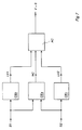
- a continuous calculation of the correlation between the signals S1 and S2 is made when these are displaced by a varying time interval ⁇ relative to each other.
- the time displacement ⁇ m which provides the highest value of the correlation integral is used as one subset for the speed determination.
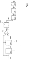
- the result of previous measurements (the previous history), modelling of the dynamic properties of the vehicle (the train), possibly other (less accurate) speed sensors, as, for example, a tachometer generator, are used as input data.
- the evaluation program which is a statistical probability calculation with adaptive weights of the various input data, then provides an MLE (Maximum Likelihood Estimation) of the instantaneous speed of the vehicle.
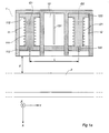
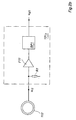
- a separate monitoring winding may be adapted to sense the amplitude and/or phase of the magnetization field.
- a monitoring unit is adapted to trigger an alarm in the event of loss of the magnetization field, or if the characteristics of the field deviate from the desired ones.
Landscapes
- Engineering & Computer Science (AREA)
- General Physics & Mathematics (AREA)
- Life Sciences & Earth Sciences (AREA)
- Sustainable Energy (AREA)
- Power Engineering (AREA)
- Transportation (AREA)
- Mechanical Engineering (AREA)
- Sustainable Development (AREA)
- Physics & Mathematics (AREA)
- Train Traffic Observation, Control, And Security (AREA)
- Measurement Of Length, Angles, Or The Like Using Electric Or Magnetic Means (AREA)
- Measuring Magnetic Variables (AREA)
- Indicating Or Recording The Presence, Absence, Or Direction Of Movement (AREA)
- Investigating Or Analyzing Materials By The Use Of Magnetic Means (AREA)
- Length Measuring Devices With Unspecified Measuring Means (AREA)
- Investigating Or Analyzing Materials By The Use Of Ultrasonic Waves (AREA)
Claims (30)
- Dispositif pour la mesure de vitesse dans un véhicule monté sur rail, caractérisé en ce qu'il comporte des moyens (G1, G2) disposés sur le véhicule et conçuspour produire, à deux emplacements de mesure différents l'un après l'autre suivant la direction longitudinale du véhicule et à une distance (L) connue l'un de l'autre, un champ magnétique qui comprend le rail (2),pour détecter, à chacun des emplacements de mesure, une configuration (S1, S2) de signal qui correspond à une variation dans le temps du champ créée par le déplacement du véhicule le long du rail,pour déterminer l'écart (τm) de temps entre les deux configurations de signal par corrélation des deux configurations de signal, etpour déterminer, sur la base de l'écart de temps et sur la base de la distance connue entre les emplacements de mesure, la vitesse (v) du véhicule.
- Dispositif suivant la revendication 1, caractérisé en ce qu'il comporte des moyens (111, 112) de production de champ conçus pour produire à chaque emplacement de mesure un champ magnétique alternatif.
- Dispositif suivant la revendication 2, caractérisé en ce que les moyens de production de champ sont conçus pour produire des champs alternatifs à une fréquence dépassant 10 kHz.
- Dispositif suivant la revendication 2, caractérisé en ce que les moyens de production de champ sont conçus pour produire des champs alternatifs avec l'une d'au moins deux fréquences (f1, f2) différentes en option.
- Dispositif suivant la revendication 4, caractérisé en ce que les moyens de production de champ sont conçus pour fonctionner alternativement à deux fréquences (f1, f2) différentes.
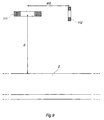
- Dispositif suivant les revendications 1 et 2, caractérisé en ce qu'il comporte deux capteurs (G1, G2) disposés à distance l'un de l'autre sur le véhicule suivant la direction (Y) longitudinale du véhicule, chaque capteur ayant une bobine (111, 121) de magnétisation, qui reçoit du courant alternatif pour produire un champ de magnétisation comportant le rail (2).
- Dispositif suivant la revendication 6, caractérisé en ce que la bobine (111, 121) de magnétisation est disposée en ayant son axe (X) longitudinal sensiblement perpendiculaire à la direction (Y) longitudinale du rail.
- Dispositif suivant la revendication 7, caractérisé en ce que la bobine (111, 121) de magnétisation est disposée en ayant son axe (X) longitudinal sensiblement vertical.
- Dispositif suivant la revendication 6, caractérisé en ce que chaque capteur (G1, G2) comporte au moins une bobine (112, 122) formant capteur distincte pour détecter des variations de champ créées par le mouvement du véhicule.
- Dispositif suivant la revendication 9, caractérisé en ce que la bobine (par exemple 112) formant capteur est disposée entre la bobine (111) de magnétisation et le rail (2).
- Dispositif suivant la revendication 9, caractérisé en ce que la bobine (par exemple 112) formant capteur est disposée en ayant sa direction (Y) de détection sensiblement perpendiculaire à la direction (X) du champ de magnétisation.
- Dispositif suivant la revendication 11, caractérisé en ce que la bobine (par exemple 112) formant capteur est disposée en ayant sa direction (Y) de détection sensiblement horizontale.
- Dispositif suivant la revendication 12, caractérisé en ce que la bobine (par exemple 112) formant capteur est disposée en ayant sa direction (Y) de détection sensiblement parallèle à la direction longitudinale du rail.
- Dispositif suivant la revendication 12, caractérisé en ce que la bobine (par exemple 112) formant capteur est disposée en ayant sa direction (Z) de détection sensiblement perpendiculaire à la direction longitudinale du rail.
- Dispositif suivant les revendications 6 et 9, caractérisé en ce que les bobines (111, 121) de magnétisation et les bobines (112, 122) formant capteur sont des bobines à air sans fer.
- Dispositif suivant la revendication 9, caractérisé en ce que le signal (Ui1) de sortie de la bobine (par exemple 112) formant capteur est conçu pour être envoyé à des moyens (SB1) destinés à détecter des variations dans la position (ϕ) de phase du signal.
- Dispositif-suivant la revendication 16, caractérisé en ce que les moyens (SB1) destinés à détecter des variations dans la position de phase du signal comportent un circuit verrouillé en phase (PLL1) destiné à produire un signal de référence de phase (ur11).
- Dispositif suivant la revendication 9, caractérisé en ce que le signal (Ui1) de sortie de la bobine formant capteur est conçu pour être envoyé à des moyens (PLL1, AGC1, F21) pour la commande électronique du point de travail des moyens (SB1) destinés à détecter des variations de la position de phase du signal.
- Dispositif suivant la revendication 18, caractérisé en ce que les moyens pour la commande électronique du point de travail comportent des moyens (PLL1, AGC1) pour produire un signal (udm1) correspondant à la valeur moyenne du signal de capteur et des moyens (F21) pour la soustraction du signal de la valeur (ud1) instantanée du signal de capteur.
- Dispositif suivant la revendication 9, caractérisé en ce qu'il comporte un premier capteur (G1) et un second (G2) et un troisième (G2') capteurs disposés à des distances (L, L') différentes du premier capteur ainsi que des moyens (SW1, SW2) de sélection conçus pour sélectionner, pour une corrélation avec le signal (ud1) de sortie du premier capteur (G1), le signal (ud2, u'd2) de sortie du second capteur (G2) ou du troisième capteur (G2').
- Dispositif suivant la revendication 20, caractérisé en ce qu'il comporte des moyens (NV, SW1, SW2) pour la sélection automatique du signal de sortie du second ou du troisième capteur en fonction de la vitesse (v) du véhicule.
- Dispositif suivant la revendication 1, caractérisé en ce que les configurations (S1, S2) de signal détectées sont conçues pour être envoyées à des moyens (DS, NV2, CE, NV3, OC) pour la détection du non mouvement du véhicule.
- Dispositif suivant la revendication 22, caractérisé en ce que les moyens (DS, NV2, CE, NV3, OC) pour la détection du non mouvement du véhicule comporte des moyens (DS, NV2) pour la détection de l'absence de variation d'une configuration (S1) de signal détectée à un emplacement de mesure.
- Dispositif suivant la revendication 23, caractérisé en ce qu'il comporte des moyens (CE, NV3) pour la détection de l'absence de corrélation des deux configurations (S1, S2) de signal détectées à deux emplacements de mesure.
- Dispositif suivant la revendication 1, caractérisé en ce qu'il comporte des moyens (M) pour la mémorisation de caractéristiques (CM) d'une configuration de signal apparaissant à un défaut du rail ainsi que des moyens (CD, COMP2) pour la détection de défauts de rail par une comparaison en continue entre les caractéristiques mémorisées et les caractéristiques (CS1) correspondantes d'une configuration (S1) de signal détectée pendant le mouvement du véhicule.
- Dispositif suivant la revendication 6, caractérisé en ce que les capteurs sont conçus pour être montés sur un bogie de véhicule.
- Dispositif suivant l'une quelconque des revendications 6 à 21, 26, caractérisé en ce que l'extension de la bobine (111) de magnétisation suivant sa direction longitudinale est considérablement plus petite que le diamètre de la bobine.
- Dispositif suivant la revendication 27, caractérisé en ce que la bobine (111) de magnétisation est une bobine à enroulement de feuilles.
- Dispositif suivant l'une quelconque des revendications 9 à 21, caractérisé en ce que la bobine (112) formant capteur est disposée à sensiblement la même distance verticale du rail que la bobine de magnétisation.
- Dispositif suivant la revendication 29, caractérisé en ce que la bobine (112) de capteur est déplacée suivant la direction longitudinale du rail (2) par rapport à la bobine (111) de magnétisation d'une distance (d/2) qui constitue approximativement la moitié de la distance (d) entre la bobine de magnétisation et le rail.
Applications Claiming Priority (3)
| Application Number | Priority Date | Filing Date | Title |
|---|---|---|---|
| SE9402350 | 1994-07-04 | ||
| SE9402350A SE515008C2 (sv) | 1994-07-04 | 1994-07-04 | Anordning för hastighetsmätning vid rälsfordon |
| PCT/SE1995/000783 WO1996001431A1 (fr) | 1994-07-04 | 1995-06-26 | Dispositif de mesure de la vitesse d'un vehicule monte sur rails |
Publications (2)
| Publication Number | Publication Date |
|---|---|
| EP0797779A1 EP0797779A1 (fr) | 1997-10-01 |
| EP0797779B1 true EP0797779B1 (fr) | 2001-08-16 |
Family
ID=20394614
Family Applications (1)
| Application Number | Title | Priority Date | Filing Date |
|---|---|---|---|
| EP95925206A Expired - Lifetime EP0797779B1 (fr) | 1994-07-04 | 1995-06-26 | Dispositif de mesure de la vitesse d'un vehicule monte sur rails |
Country Status (8)
| Country | Link |
|---|---|
| US (1) | US5825177A (fr) |
| EP (1) | EP0797779B1 (fr) |
| JP (1) | JP4112610B2 (fr) |
| AT (1) | ATE204386T1 (fr) |
| AU (1) | AU2941095A (fr) |
| DE (1) | DE69522237T2 (fr) |
| SE (1) | SE515008C2 (fr) |
| WO (1) | WO1996001431A1 (fr) |
Families Citing this family (33)
| Publication number | Priority date | Publication date | Assignee | Title |
|---|---|---|---|---|
| US6292112B1 (en) * | 1992-06-25 | 2001-09-18 | 3461513 Canada Inc. | Vehicle presence detection system |
| DE19812070C1 (de) * | 1998-03-19 | 1999-08-19 | Siemens Ag | Verfahren und Vorrichtung zur näherungsweisen Geschwindigkeitsbestimmung bei einem spurgeführten Fahrzeug |
| US6043774A (en) * | 1998-03-25 | 2000-03-28 | Honeywell Inc. | Near-range proximity sensor having a fast-tracking analog |
| US6570497B2 (en) * | 2001-08-30 | 2003-05-27 | General Electric Company | Apparatus and method for rail track inspection |
| US9733625B2 (en) | 2006-03-20 | 2017-08-15 | General Electric Company | Trip optimization system and method for a train |
| US10308265B2 (en) | 2006-03-20 | 2019-06-04 | Ge Global Sourcing Llc | Vehicle control system and method |
| CN100585404C (zh) * | 2002-10-11 | 2010-01-27 | 迪姆肯公司 | 速度检测装置 |
| US9950722B2 (en) | 2003-01-06 | 2018-04-24 | General Electric Company | System and method for vehicle control |
| US7676345B2 (en) * | 2003-07-07 | 2010-03-09 | Nira Dynamics Ab | Method and system of determining the absolute velocity of a vehicle |
| US9956974B2 (en) | 2004-07-23 | 2018-05-01 | General Electric Company | Vehicle consist configuration control |
| US9828010B2 (en) | 2006-03-20 | 2017-11-28 | General Electric Company | System, method and computer software code for determining a mission plan for a powered system using signal aspect information |
| US8224509B2 (en) * | 2006-08-25 | 2012-07-17 | General Atomics | Linear synchronous motor with phase control |
| JP2009084009A (ja) * | 2007-10-01 | 2009-04-23 | Hitachi Ltd | 移動体速度検出装置 |
| DE602007006677D1 (de) | 2007-11-28 | 2010-07-01 | Bombardier Transp Gmbh | Schienenpositionierungssystem |
| US8914171B2 (en) | 2012-11-21 | 2014-12-16 | General Electric Company | Route examining system and method |
| US8149160B2 (en) * | 2009-10-27 | 2012-04-03 | Systems And Materials Research Corporation | Method and apparatus using non-contact measuring device to determine rail distance traveled |
| DE102010005336A1 (de) * | 2010-01-21 | 2011-07-28 | SITEMA GmbH & Co. KG, 76135 | Vorrichtung und Verfahren zum Erfassen einer Bewegungsgröße eines magnetisierbaren Objekts |
| JP5371908B2 (ja) * | 2010-08-17 | 2013-12-18 | 公益財団法人鉄道総合技術研究所 | 走行速度検出装置 |
| JP5388997B2 (ja) * | 2010-11-25 | 2014-01-15 | 三菱電機株式会社 | 速度計測装置 |
| CN102519496B (zh) * | 2011-11-25 | 2014-04-16 | 上海交通大学 | 直线运动检测装置 |
| WO2014026091A2 (fr) | 2012-08-10 | 2014-02-13 | General Electric Company | Système et procédé d'examen d'itinéraire |
| CA2806186A1 (fr) * | 2013-02-15 | 2014-08-15 | Extreme Telematics Corp. | Capteur de vitesse pour un systeme de remontee a plongeur |
| US9255913B2 (en) | 2013-07-31 | 2016-02-09 | General Electric Company | System and method for acoustically identifying damaged sections of a route |
| US9718405B1 (en) * | 2015-03-23 | 2017-08-01 | Rosco, Inc. | Collision avoidance and/or pedestrian detection system |
| DE102015217535B3 (de) * | 2015-09-14 | 2016-12-22 | Thales Deutschland Gmbh | Verfahren zur Geschwindigkeitsermittlung eines schienengebundenen Fahrzeugs |
| DE102016105413B4 (de) * | 2016-03-23 | 2019-11-14 | Karlsruher Institut für Technologie | Geschwindigkeitsmessverfahren und geschwindigkeitsmessanordnung |
| JP6625489B2 (ja) * | 2016-06-28 | 2019-12-25 | 株式会社日立ハイテクファインシステムズ | レール検査システム |
| CN109178028B (zh) * | 2018-11-01 | 2024-08-13 | 中车兰州机车有限公司 | 机车防弛缓报警装置性能检测设备 |
| RU2704632C1 (ru) * | 2019-04-16 | 2019-10-30 | Общество с ограниченной ответственностью «Научно-производственное предприятие «САРМАТ» | Измеритель параметров движения составного транспорта и способ его работы |
| US12115916B2 (en) | 2021-02-01 | 2024-10-15 | Rosco, Inc. | Downlighting signal and illumination mirror head for vehicle |
| US12286145B2 (en) * | 2021-04-02 | 2025-04-29 | Transportation Ip Holdings, Llc | Vehicle control system |
| DE102022123270A1 (de) | 2021-09-16 | 2023-03-16 | Eckehard Schnieder | Transportsystem |
| DE102024202672A1 (de) | 2024-03-21 | 2025-09-25 | Robert Bosch Gesellschaft mit beschränkter Haftung | Verfahren zur Geschwindigkeitsermittlung eines Fahrzeugs, insbesondere eines Schienenfahrzeugs, basierend auf einem Laufzeitunterschied und einer Geschwindigkeitsfehlerinformation |
Family Cites Families (9)
| Publication number | Priority date | Publication date | Assignee | Title |
|---|---|---|---|---|
| BE555801A (fr) * | ||||
| DE2164312A1 (de) * | 1971-12-23 | 1973-06-28 | Siemens Ag | Einrichtung zur weg- und geschwindigkeitsmessung auf schienenfahrzeugen |
| US4283031A (en) * | 1977-12-14 | 1981-08-11 | Finch Colin M | System controlling apparatus which compares signals from sensors monitoring passing objects with pre-determined parameter information to control the system |
| US4179744A (en) * | 1978-03-02 | 1979-12-18 | Magtronics Incorporated | Method and apparatus for analyzing performance of electric-traction-motor powered vehicles and electrical operating components thereof |
| JPS5580057A (en) * | 1978-12-13 | 1980-06-16 | Nippon Soken Inc | Contactless speed measuring apparatus |
| GB2062235A (en) * | 1979-01-05 | 1981-05-20 | British Gas Corp | Measuring velocity and/or distance travelled |
| GB2094981B (en) * | 1981-03-17 | 1984-04-18 | Standard Telephones Cables Ltd | Magnetic velocity measuring systems |
| ATE120145T1 (de) * | 1989-11-01 | 1995-04-15 | Electromotive Systems Inc | Vorrichtung und verfahren zur bestimmung eines oder mehrerer betriebsdaten eines schienengebundenen fahrzeuges. |
| US5301130A (en) * | 1992-10-22 | 1994-04-05 | Hughes Aircraft Company | Absoulte velocity sensor |
-
1994
- 1994-07-04 SE SE9402350A patent/SE515008C2/sv not_active IP Right Cessation
-
1995
- 1995-06-26 DE DE69522237T patent/DE69522237T2/de not_active Expired - Lifetime
- 1995-06-26 AT AT95925206T patent/ATE204386T1/de active
- 1995-06-26 EP EP95925206A patent/EP0797779B1/fr not_active Expired - Lifetime
- 1995-06-26 AU AU29410/95A patent/AU2941095A/en not_active Abandoned
- 1995-06-26 WO PCT/SE1995/000783 patent/WO1996001431A1/fr not_active Ceased
- 1995-06-26 US US08/765,629 patent/US5825177A/en not_active Expired - Lifetime
- 1995-06-26 JP JP50382796A patent/JP4112610B2/ja not_active Expired - Fee Related
Also Published As
| Publication number | Publication date |
|---|---|
| DE69522237T2 (de) | 2002-09-05 |
| DE69522237D1 (de) | 2001-09-20 |
| SE515008C2 (sv) | 2001-05-28 |
| ATE204386T1 (de) | 2001-09-15 |
| WO1996001431A1 (fr) | 1996-01-18 |
| SE9402350L (sv) | 1996-01-05 |
| SE9402350D0 (sv) | 1994-07-04 |
| AU2941095A (en) | 1996-01-25 |
| US5825177A (en) | 1998-10-20 |
| EP0797779A1 (fr) | 1997-10-01 |
| JPH10506182A (ja) | 1998-06-16 |
| JP4112610B2 (ja) | 2008-07-02 |
Similar Documents
| Publication | Publication Date | Title |
|---|---|---|
| EP0797779B1 (fr) | Dispositif de mesure de la vitesse d'un vehicule monte sur rails | |
| CA1271242A (fr) | Detecteur de dommages aux roues | |
| CN101242984B (zh) | 使用霍尔效应器件的铁路车轮传感器 | |
| US6405141B1 (en) | Dynamic track stiffness measurement system and method | |
| US6539293B2 (en) | Method and device for monitoring bogies of multi-axle vehicles | |
| US6995556B2 (en) | Electromagnetic gage sensing system and method for railroad track inspection | |
| CN101750001B (zh) | 低速磁浮列车自诊断式悬浮间隙传感器 | |
| JP3375968B2 (ja) | 磁力計車両検出器 | |
| CN109270475B (zh) | 高速磁浮长定子牵引行波磁场检测系统 | |
| EP1097076A1 (fr) | Procede et dispositif de detection des roues de chemin de fer defectueuses | |
| Engelberg et al. | Eddy current sensor system for non-contact speed and distance measurement of rail vehicles | |
| CN111114338A (zh) | 一种高速磁悬浮列车测速传感器及磁悬浮列车 | |
| ES2743456T3 (es) | Procedimiento y disposición para medir separaciones de un vehículo ferroviario con respecto a objetos dispuestos lateralmente al vehículo ferroviario | |
| JP4176311B2 (ja) | レール走行車両の速度測定法およびそのための装置 | |
| JP3686184B2 (ja) | 車両の輪重計測装置 | |
| RU2248898C2 (ru) | Устройство контроля проследования железнодорожного подвижного состава | |
| JP3091148B2 (ja) | 車両検出装置 | |
| JP3504359B2 (ja) | トロリ線の高さ・偏位測定装置 | |
| WO2019002852A1 (fr) | Appareil et procédé de détection de roue de véhicule ferroviaire | |
| JPS5821504A (ja) | 軌道狂い測定装置 | |
| JPH07123533A (ja) | 列車速度制御装置 | |
| JP2910167B2 (ja) | 搬送車の誘導方法 | |
| JP5837790B2 (ja) | リアクションプレートの高さモニタリング方法 | |
| JPS6116921B2 (fr) | ||
| JPH02108904A (ja) | 連続位置検知による列車長検出方法 |
Legal Events
| Date | Code | Title | Description |
|---|---|---|---|
| PUAI | Public reference made under article 153(3) epc to a published international application that has entered the european phase |
Free format text: ORIGINAL CODE: 0009012 |
|
| 17P | Request for examination filed |
Effective date: 19970122 |
|
| AK | Designated contracting states |
Kind code of ref document: A1 Designated state(s): AT BE CH DE DK ES FR GB IT LI NL |
|
| GRAG | Despatch of communication of intention to grant |
Free format text: ORIGINAL CODE: EPIDOS AGRA |
|
| 17Q | First examination report despatched |
Effective date: 20000523 |
|
| GRAG | Despatch of communication of intention to grant |
Free format text: ORIGINAL CODE: EPIDOS AGRA |
|
| GRAH | Despatch of communication of intention to grant a patent |
Free format text: ORIGINAL CODE: EPIDOS IGRA |
|
| RAP1 | Party data changed (applicant data changed or rights of an application transferred) |
Owner name: DAIMLERCHRYSLER AG |
|
| GRAH | Despatch of communication of intention to grant a patent |
Free format text: ORIGINAL CODE: EPIDOS IGRA |
|
| GRAA | (expected) grant |
Free format text: ORIGINAL CODE: 0009210 |
|
| AK | Designated contracting states |
Kind code of ref document: B1 Designated state(s): AT BE CH DE DK ES FR GB IT LI NL |
|
| PG25 | Lapsed in a contracting state [announced via postgrant information from national office to epo] |
Ref country code: NL Free format text: LAPSE BECAUSE OF FAILURE TO SUBMIT A TRANSLATION OF THE DESCRIPTION OR TO PAY THE FEE WITHIN THE PRESCRIBED TIME-LIMIT Effective date: 20010816 Ref country code: LI Free format text: LAPSE BECAUSE OF FAILURE TO SUBMIT A TRANSLATION OF THE DESCRIPTION OR TO PAY THE FEE WITHIN THE PRESCRIBED TIME-LIMIT Effective date: 20010816 Ref country code: CH Free format text: LAPSE BECAUSE OF FAILURE TO SUBMIT A TRANSLATION OF THE DESCRIPTION OR TO PAY THE FEE WITHIN THE PRESCRIBED TIME-LIMIT Effective date: 20010816 Ref country code: BE Free format text: LAPSE BECAUSE OF FAILURE TO SUBMIT A TRANSLATION OF THE DESCRIPTION OR TO PAY THE FEE WITHIN THE PRESCRIBED TIME-LIMIT Effective date: 20010816 Ref country code: AT Free format text: LAPSE BECAUSE OF FAILURE TO SUBMIT A TRANSLATION OF THE DESCRIPTION OR TO PAY THE FEE WITHIN THE PRESCRIBED TIME-LIMIT Effective date: 20010816 |
|
| REF | Corresponds to: |
Ref document number: 204386 Country of ref document: AT Date of ref document: 20010915 Kind code of ref document: T |
|
| REG | Reference to a national code |
Ref country code: CH Ref legal event code: EP |
|
| RAP2 | Party data changed (patent owner data changed or rights of a patent transferred) |
Owner name: BOMBARDIER TRANSPORTATION GMBH |
|
| REF | Corresponds to: |
Ref document number: 69522237 Country of ref document: DE Date of ref document: 20010920 |
|
| NLT2 | Nl: modifications (of names), taken from the european patent patent bulletin |
Owner name: BOMBARDIER TRANSPORTATION GMBH |
|
| PG25 | Lapsed in a contracting state [announced via postgrant information from national office to epo] |
Ref country code: DK Free format text: LAPSE BECAUSE OF FAILURE TO SUBMIT A TRANSLATION OF THE DESCRIPTION OR TO PAY THE FEE WITHIN THE PRESCRIBED TIME-LIMIT Effective date: 20011116 |
|
| REG | Reference to a national code |
Ref country code: GB Ref legal event code: IF02 |
|
| ET | Fr: translation filed | ||
| NLV1 | Nl: lapsed or annulled due to failure to fulfill the requirements of art. 29p and 29m of the patents act | ||
| PG25 | Lapsed in a contracting state [announced via postgrant information from national office to epo] |
Ref country code: ES Free format text: LAPSE BECAUSE OF FAILURE TO SUBMIT A TRANSLATION OF THE DESCRIPTION OR TO PAY THE FEE WITHIN THE PRESCRIBED TIME-LIMIT Effective date: 20020228 |
|
| REG | Reference to a national code |
Ref country code: CH Ref legal event code: PL |
|
| PLBE | No opposition filed within time limit |
Free format text: ORIGINAL CODE: 0009261 |
|
| STAA | Information on the status of an ep patent application or granted ep patent |
Free format text: STATUS: NO OPPOSITION FILED WITHIN TIME LIMIT |
|
| 26N | No opposition filed | ||
| PGFP | Annual fee paid to national office [announced via postgrant information from national office to epo] |
Ref country code: DE Payment date: 20120622 Year of fee payment: 18 |
|
| PGFP | Annual fee paid to national office [announced via postgrant information from national office to epo] |
Ref country code: FR Payment date: 20120705 Year of fee payment: 18 Ref country code: GB Payment date: 20120622 Year of fee payment: 18 |
|
| PGFP | Annual fee paid to national office [announced via postgrant information from national office to epo] |
Ref country code: IT Payment date: 20120628 Year of fee payment: 18 |
|
| GBPC | Gb: european patent ceased through non-payment of renewal fee |
Effective date: 20130626 |
|
| REG | Reference to a national code |
Ref country code: FR Ref legal event code: ST Effective date: 20140228 |
|
| REG | Reference to a national code |
Ref country code: DE Ref legal event code: R119 Ref document number: 69522237 Country of ref document: DE Effective date: 20140101 |
|
| PG25 | Lapsed in a contracting state [announced via postgrant information from national office to epo] |
Ref country code: GB Free format text: LAPSE BECAUSE OF NON-PAYMENT OF DUE FEES Effective date: 20130626 Ref country code: DE Free format text: LAPSE BECAUSE OF NON-PAYMENT OF DUE FEES Effective date: 20140101 |
|
| PG25 | Lapsed in a contracting state [announced via postgrant information from national office to epo] |
Ref country code: FR Free format text: LAPSE BECAUSE OF NON-PAYMENT OF DUE FEES Effective date: 20130701 Ref country code: IT Free format text: LAPSE BECAUSE OF NON-PAYMENT OF DUE FEES Effective date: 20130626 |