EP0797863B1 - Magnetische kupplung - Google Patents
Magnetische kupplung Download PDFInfo
- Publication number
- EP0797863B1 EP0797863B1 EP96935034A EP96935034A EP0797863B1 EP 0797863 B1 EP0797863 B1 EP 0797863B1 EP 96935034 A EP96935034 A EP 96935034A EP 96935034 A EP96935034 A EP 96935034A EP 0797863 B1 EP0797863 B1 EP 0797863B1
- Authority
- EP
- European Patent Office
- Prior art keywords
- rotary
- arrangement according
- magnets
- rotary feedthrough
- feedthrough arrangement
- Prior art date
- Legal status (The legal status is an assumption and is not a legal conclusion. Google has not performed a legal analysis and makes no representation as to the accuracy of the status listed.)
- Expired - Lifetime
Links
Images


Classifications
-
- H—ELECTRICITY
- H10—SEMICONDUCTOR DEVICES; ELECTRIC SOLID-STATE DEVICES NOT OTHERWISE PROVIDED FOR
- H10P—GENERIC PROCESSES OR APPARATUS FOR THE MANUFACTURE OR TREATMENT OF DEVICES COVERED BY CLASS H10
- H10P72/00—Handling or holding of wafers, substrates or devices during manufacture or treatment thereof
- H10P72/04—Apparatus for manufacture or treatment
- H10P72/0431—Apparatus for thermal treatment
- H10P72/0436—Apparatus for thermal treatment mainly by radiation
-
- H—ELECTRICITY
- H02—GENERATION; CONVERSION OR DISTRIBUTION OF ELECTRIC POWER
- H02K—DYNAMO-ELECTRIC MACHINES
- H02K49/00—Dynamo-electric clutches; Dynamo-electric brakes
- H02K49/10—Dynamo-electric clutches; Dynamo-electric brakes of the permanent-magnet type
- H02K49/104—Magnetic couplings consisting of only two coaxial rotary elements, i.e. the driving element and the driven element
- H02K49/106—Magnetic couplings consisting of only two coaxial rotary elements, i.e. the driving element and the driven element with a radial air gap
Definitions
- This invention relates to magnetic transmission couplings for transmitting drive from one member to another, and in particular, but not exclusively, to rotary feedthrough transmission arrangements for use with a vacuum enclosure to allow transmission of rotation across a vacuum membrane and to allow access for services such as power, cooling, instrumentation, etc.
- the workpiece for example a semiconductor wafer, an optical component, or a magnetic storage device may be subjected to a thin film deposition process, in which a material is sputtered, evaporated or injected as gas towards a heated substrate contained in a vacuum or other controlled atmosphere. It is often critical that the vacuum is at an extremely low pressure and/or kept isolated from atmosphere. Furthermore, this may require the process instrumentation to be of metal construction with the ability to withstand temperatures of typically 250°C or more.
- the heated substrate may need to be rotated at a predetermined substantially smooth speed.
- This requirement of transmitting rotation into the vacuum enclosure whilst maintaining the integrity of the vacuum enclosure has led to several designs of rotary feedthrough, an example being that described in British Patent GB 2213316.
- This is a concentric magnetic coupling arrangement, and drive is transmitted across a cylindrical wall of the enclosure to an inner magnetic array on a torque tube from an outer concentric magnetic array rotatably mounted on the cylindrical wall.
- a further disadvantage of the concentric arrangement is that it does not allow drive ratios of other than unity.
- the concentric arrangement requires that the outer magnet array be mounted on large diameter bearings which run on the cylindrical wall or membrane of the coupling. Such large bearings are expensive and this is another factor which limits the diameter and thus applications of the arrangement.
- drive member and the driven member comprise concentric co-operating annular drive members, in which each drive member is magnetised as a multiple magnet.
- These conventional magnetic couplings may be termed "static" couplings as, in normal use, the magnets do not move relative to each other, and thus they do not allow drive ratios of other than 1:1.
- the construction and magnetisation of the annuli requires machining of special grade ferromagnetic material and either a subsequent complex and lengthy magnetisation process, or provision of an electromagnet. In some cases preferred magnetisations cannot be achieved.
- Magnetic rotary couplings exist in which the drive member and the driven member comprise co-operating annular drive members, in which each drive member is magnetised as a multiple magnet.
- These conventional magnetic couplings may be termed "static" couplings as, in normal use, the magnets do not move relative to each other, and thus they do not allow drive ratios of other than 1:1.
- the construction and magnetisation of the annuli requires machining of special grade ferromagnetic material and either a subsequent lengthy magnetisation process, or provision of an electromagnet.
- GB 2240666A shows an arrangement disclosing a concentric arrangement in which the drive member and driven member each comprise a plurality of tangentially polarised magnets interposed between radially polarised magnets. This arrangement requires special machining and magnetisation and the magnets are contiguous rather than spaced.
- GB 2284105 shows an arrangement in which a shaft is provided with a spiral track arrangement which allows drive to be transmitted in unison to a plurality of rollers. This arrangement requires complex formation of the spiral track arrangement and does not suggest the use of discrete magnets in a circular array.
- GB 1579646 discloses a concentric arrangement in which drive is transmitted between two rotors which are made up of specially curved magnets butted up against each other. There is no suggestion of using standard rectangular sectioned magnets, nor of leaving a gap between adjacent magnets.
- U.S. 5013949 discloses a transmission arrangement in which a planetary scheme is used to transmit rotation between two concentric shafts, with a pre-set drive ratio.
- This arrangement employs specially formed magnets of part-cylindrical section and there is no suggestion of using standard magnets of rectangular section.
- the planetary nature of the scheme renders it impractical where the drive and driven member are to be isolated by a membrane.
- this invention provides a rotary feedthrough arrangement for providing rotational drive via an aperture in the wall of an enclosure which is sealed in use, said arrangement including:-
- Preferred arrangements allow drive to be transmitted relatively smoothly across a membrane at a variety of different drive ratios with low or negligible angular backlash. Furthermore the provision of a non-concentric drive removes a design constraint as it is no longer strictly essential to mount the inner magnetic drive member closely within a cylindrical membrane which itself is located concentrically within the outer drive member, provided there is sufficient magnetic coupling between the adjacent regions of the magnetic coupling members.
- the membrane element may include or be connected to a flange member of diameter greater than that of the external drive member.
- each series comprises at least six and preferably at least eight magnets.
- a typical arrangement uses sixteen magnets for negligible angular backlash.
- the drive members may include two or more circumferential stacks of discretely spaced magnets. The magnets are preferably rare earth magnets.
- discrete magnetic elements does not preclude the possibility of the elements being "potted” in, e.g. a resin, or being otherwise integrated into the drive region.
- each of said circumferential series of discrete magnet elements comprises two generally circular inner and outer keeper elements with said magnet elements disposed between said keeper elements.
- the pole axes of the magnet elements on the rotary tubular element and on the drive member may be radially disposed, and successive magnet elements in each series may have opposite polarity.
- the feedthrough arrangement may include an elongate relatively fixed member extending at least partly through said rotary tubular element to project in use into said enclosure.
- the membrane element is preferably at least partially cylindrical, closely surrounding said rotary tubular element with clearance.
- the further connector member is preferably of external diameter greater than that of said external drive member.
- At least one of said internal and external drive members is made up of two or more annular series of discrete spaced magnets.
- the numbers of the magnets on said internal and external drive members mayprovide a unity drive ratio of 1:1, or they may provide a different ratio.
- the external drive member is preferably rotatably attached to a bracket connected to or forming part of the membrane element.
- the external drive member may be mounted for rotation by bearing assemblies of diameter substantially smaller than that of the drive member.
- Preferred arrangements of this invention do not require lubricants or coolants other than any lubricants required in the normal manner for shaft bearings etc. Compared to conventional gear systems, the preferred arrangements are contactless and so the "meshing" regions are wear-free and do not generate particulates or other debris.
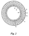
- each disc 10, 12 is mounted on respective spaced parallel shafts 14, 16 by bearings 18, 20.
- a series of spaced magnets 22 of rectangular cross section with their pole axes radial and adjacent magnets being of alternate polarity.
- Each disc includes an inner annular keeper 24 abutting the inner ends of the magnets and an outer annular keeper 26 encircling the outer ends of the magnets. In the equilibrium position the drive discs align so that the closest magnet on one disc faces a magnet of opposite polarity on the other disc, thus providing strong radial attraction, and zero net tangential force between the drive discs.
- the equilibrium position is momentarily disturbed so that the filed lines between previously aligned magnets now have a tangential component which causes the other disc to rotate to re-establish equilibrium, until the next pair of magnets of opposite polarity are brought into alignment.
- the system provides a form of magnetic gearing with high rigidity and minimal backlash, with the gear ratio determined by the number of magnets of each drive disc.
- the drive discs 10, 12 are disposed concentrically, one within the other, with the rotary axes of the shafts 14 and 16 parallel.
- the drive discs 10 and 12 rotate with each other, unless the torque transmitted overcomes the magnetic coupling force, and so the drive ratio is 1:1.
- the gearing is contactless, experiences little or no cogging, provides a smooth drive, and is capable of transmitting significant amounts of torque. If greater torque capabilities are required, further co-operating drive discs may be located on the shafts, to provide a stacked arrangement.
- the magnets may instead be arranged to have the same polarity, i.e. with all N (or S) faces on one drive member and all S (or N) faces on the other. Although this would not give as good rigidity this could be useful where an odd number of magnets are used, or where only a few are used, or where only low coupling torque or low "break out" is required.
- the third embodiment of this invention comprises a mechanism for heating semiconductor substrates, during thin film deposition.
- Thin film deposition is a process used in the manufacture or research of semiconductor electronic devices, optical components, magnetic storage devices or any other technology requiring controlled growth. During the process materials are sputtered, evaporated or injected as gasses towards a heated substrate contained in a vacuum. It is often critical that the vacuum is an extremely low pressure. This requires process instrumentation to be of all metal construction, with the ability to tolerate temperatures of 250°C (needed to accelerate outgassing process).
- the heated substrate In order to permit uniform thickness of the deposited films, the heated substrate should be rotated.
- the mechanism 30 is designed to be sealingly coupled to an access aperture 32 in the wall 34 of a vacuum vessel by means of a main flange 36.
- the main flange 36 is sealingly coupled to a non-ferrous thin metal membrane 38 which is connected to its other end to a flange 40 defining an access port.
- a service entry flange could be sealingly secured to the flange 40 and carry an elongate support projecting into the vacuum vessel, but in this particular embodiment an optical Z shift module 86 is illustrated.
- the flange 40 is sealingly connected to a further flange 42 itself sealingly coupled to a tube 44 which incorporates a bellows arrangement 46 so that the effective length of the tube 44 may be increased and decreased.
- the tube 44 is connected to a flange 48 which is sealingly coupled to a flange 50 having a bore in which a stiff tube 52 (otherwise refered to herein as a fixed member) is sealed.
- the stiff tube 52 extends through the bore of the extendable/contractible tube 44, and the bore of the membrane 38 to project into the vacuum vessel. At its inner end, the stiff tube carries a heating module 54.
- the stiff tube 52 has a substantially larger bore than conventional vacuum feedthrough arrangements and allows high current leads 56 and other services such as multiple thermocouples, diagnostics, water cooling pipes and differential pumping (not shown) to be passed through the stiff tube 52.
- the outer end of the stiff tube 52 carries a flange 58 which is sealingly connected to a service entry flange 60.
- the membrane 38, extendable/contractible tube 44 and the outer end of the stiff tube 52 together isolate the interior from the exterior.
- a torque tube 62 (otherwise referred to herein as a rotary tubular element) is mounted concentrically within the membrane 38 by means of bearing arrangements 64 running in bores in the main flange 36 and a further flange 40 (otherwise referred to herein as a connector member and a further connector member, respectively.
- the torque tube extends inwardly beyond the main flange 36 to project into the interior of the vacuum vessel. At its inner end it is connected to a substrate support cradle 66 which holds a substrate 68 and in operation spins the substrate in front of the heater module 54.
- the torque tube 62 carries on its outer periphery one or more annular series of discrete magnets 70 of rectangular cross section.
- the magnets are kept in place by inner keepers 72 and the number of magnets, their spacing and alternate polarity may typically be similar to that shown in Figure 1.
- the size and location of the magnets is such that they fit closely within the nonmagnetic membrane 38 so that the torque tube 62 may spin freely.
- An outer drive rotor 74 (otherwise referred to herin as an external drive member) comprises three similar annular series of magnets 70 held in place by keepers 72.
- the number, spacing and polarity of the magnets may be typically similar to that shown in Figure 1.
- the drive rotor 74 is mounted for rotation about an axis parallel to the rotational axis of the torque tube 62 by means of two small diameter stub axles 76 which are received in bearings 78 supported at one end by a bracket 80 connected to the main flange and at the other end by a bracket 82 connected to the further flange 40, so that the drive rotor is in magnetic torque-transmitting relationship with the magnets on the torque tube 62.
- the drive rotor 74 is driven by means of a motor 84 and a drive belt (not shown) and pulley system.
- the substrate 68 may be spun in front of the heater module 54 at a speed determined by the rotational speed of the motor 84 and the drive ratio between the drive member and the torque tube.
- the optional Z axis module 86 is connected between the flange 42 and flange 48 to vary the effective length of the extendable/contractible tube 44 and thus to vary the longitudinal or Z axis displacement between the heater module 54 and the rear of the substrate 68.
- the Z axis module may be driven by means of a motor or a hand wheel.
- the internal diameter of the stiff tube 52 is substantially larger than those of conventional arrangements.
- the flange 40 has to be of much smaller diameter because it must be sufficiently small for the outer concentric drive member to pass over it for servicing. This constraint means that the diameter of the inner stiff tube is much smaller.
- the access port may have a diameter of 50mm or far larger. Conventional concentric systems are limited to about 15mm diameter.
Landscapes
- Engineering & Computer Science (AREA)
- Power Engineering (AREA)
- Dynamo-Electric Clutches, Dynamo-Electric Brakes (AREA)
Claims (11)
- Antriebsdurchführung zum Durchführen eines Drehantriebs durch eine Öffnung (32) in einer Wandung (34) eines Gehäuses, welches im Betrieb dicht verschlossen ist, wobei die Antriebsdurchführung folgendes umfaßt,dadurch gekennzeichnet, daßein Verbindungselement (36) zum dichtenden Befestigen an der Öffnung (32);ein eisenloses Membranelement (38), welches im wesentlichen röhrenförmig ausgebildet ist und dichtend an einem Endbereich an dem Verbindungselement (36) befestigt ist;ein weiteres Verbindungselement (40), welches dichtend mit einem anderen Endbereich des Membranelementes (38) verbunden ist;ein längliches, drehbares Rohrelement (62), welches wenigstens teilweise innerhalb des röhrenförmigen Membranelementes (38) angeordnet und bzgl. diesem drehbar ist;ein magnetisches Element, welches mit dem länglichen, drehbaren Rohrelement (62) fest verbunden ist und eine oder mehrere von in Umfangsrichtung angeordneten Gruppen einzelner Magnetelemente (70) umfaßt;ein drehbar befestigtes, extemes Antriebselement (74), welches außerhalb des Membranelementes (38) angeordnet ist und eine oder mehrere von in Umfangsrichtung angeordneten Gruppen einzelner Magnetelemente (70) umfaßt, die in drehmomentübertragender Verbindung mit den jeweiligenMagnetelementen des drehbaren Rohrelementes (62) stehen;
das externe Antriebselement derart angeordnet ist, daß dessen Drehachse im wesentlichen parallel, jedoch beabstandet von der Drehachse des drehbaren Rohrelementes (62) ausgerichtet ist. - Antriebsdurchführung gemäß Anspruch 1, dadurch gekennzeichnet, daß jede der in Umfangsrichtung angeordnete Gruppe einzelner Magnetelemente zwei im wesentlichen kreisförmige innere und äußere Käfigelemente (72) aufweist, wobei die Magnetelemente (70) zwischen den Käfigelementen (72) angeordnet sind.
- Antriebsdurchführung gemäß Anspruch1 oder 2, dadurch gekennzeichnet, daß die Polachsen der Magnetelemente (70) des drehbaren Rohrelementes (62) und des Antriebselementes (74) radial angeordnet sind.
- Antriebsdurchführung gemäß wenigstens einem der vorhergehenden Ansprüche, dadurch gekennzeichnet, daß aufeinander folgende Magnetelemente (70) jeder Gruppe entgegengesetzte Polarität aufweisen.
- Antriebsdurchführung gemäß wenigstens einem der vorhergehenden Ansprüche, dadurch gekennzeichnet, daß dieses femer ein längliches, feststehendes Element (52) umfaßt, welches sich wenigstens teilweise durch das drehbare Rohrelement (62) erstreckt und im Betrieb in das Gehäuse hinein ragt.
- Antriebsdurchführung gemäß wenigstens einem der vorhergehenden Ansprüche, dadurch gekennzeichnet, daß das Membranelement (38) das drehbare Rohrelement (62) wenigstens teilweise zylindrisch eng mit einem vorbestimmt Spiel umschließt.
- Antriebsdurchführung gemäß wenigstens einem der vorhergehenden Ansprüche, dadurch gekennzeichnet, daß das weitere Verbindungselement (40) einen äußeren Durchmesser aufweist, welcher größer ist als der äußere Durchmesse des externen Antriebselementes.
- Antriebsdurchführung gemäß wenigstens einem der vorhergehenden Ansprüche, dadurch gekennzeichnet, daß das interne und/oder externe Antriebselement aus zwei oder mehr ringförmigen Gruppen einzelner, beabstandeter Magnete (70) aufgebaut ist.
- Antriebsdurchführung gemäß wenigstens einem der vorhergehenden Ansprüche, dadurch gekennzeichnet, daß die Anzahl der Magnete auf dem internen und externen Antriebselement derart ist, daß ein Übersetzungsverhältnis von 1:1 zur Verfügung steht
- Antriebsdurchführung gemäß wenigstens einem der vorhergehenden Ansprüche, dadurch gekennzeichnet, daß das externe Antriebselement drehbar mit einer Klammer verbunden ist, welche am Membranelement (38) befestigt ist oder einen Teil des Membranelementes (38) ausbildet.
- Antriebsdurchführung gemäß wenigstens einem der vorhergehenden Ansprüche, dadurch gekennzeichnet, daß das externe Antriebselement (74) mittels Lageranordnungen (78) drehbar gelagert ist, dessen Durchmesser im wesentlichen kleiner ist als derjenige des Antriebselementes (74).
Applications Claiming Priority (5)
| Application Number | Priority Date | Filing Date | Title |
|---|---|---|---|
| GB9521237 | 1995-10-17 | ||
| GBGB9521237.9A GB9521237D0 (en) | 1995-10-17 | 1995-10-17 | Transmission systems |
| GB9611937 | 1996-06-07 | ||
| GBGB9611937.5A GB9611937D0 (en) | 1995-10-17 | 1996-06-07 | Transmission systems |
| PCT/GB1996/002558 WO1997015110A1 (en) | 1995-10-17 | 1996-10-17 | Magnetic transmission couplings |
Publications (2)
| Publication Number | Publication Date |
|---|---|
| EP0797863A1 EP0797863A1 (de) | 1997-10-01 |
| EP0797863B1 true EP0797863B1 (de) | 2001-05-16 |
Family
ID=26307963
Family Applications (1)
| Application Number | Title | Priority Date | Filing Date |
|---|---|---|---|
| EP96935034A Expired - Lifetime EP0797863B1 (de) | 1995-10-17 | 1996-10-17 | Magnetische kupplung |
Country Status (5)
| Country | Link |
|---|---|
| US (1) | US5902185A (de) |
| EP (1) | EP0797863B1 (de) |
| AU (1) | AU7313796A (de) |
| DE (1) | DE69612834T2 (de) |
| WO (1) | WO1997015110A1 (de) |
Families Citing this family (23)
| Publication number | Priority date | Publication date | Assignee | Title |
|---|---|---|---|---|
| US6099467A (en) * | 1998-03-27 | 2000-08-08 | Karl Storz Gmbh & Co. Kg | Device for positioning components within endoscopic systems |
| JP4605853B2 (ja) * | 2000-04-20 | 2011-01-05 | 東京エレクトロン株式会社 | 熱処理装置、熱処理システム及び熱処理方法 |
| US6949854B1 (en) * | 2001-03-16 | 2005-09-27 | Michael Schlicht | Method and apparatus for a continuously variable-ratio transmission |
| DE202005020288U1 (de) * | 2005-12-23 | 2007-05-03 | H. Wernert & Co. Ohg | Permanentmagnetische berührungsfreie Radialdrehkupplung |
| EP2056432B1 (de) * | 2007-10-29 | 2015-04-15 | Grundfos Management A/S | Magnetische Kupplung |
| US8760250B2 (en) | 2009-06-02 | 2014-06-24 | Correlated Magnetics Rsearch, LLC. | System and method for energy generation |
| US8174347B2 (en) | 2010-07-12 | 2012-05-08 | Correlated Magnetics Research, Llc | Multilevel correlated magnetic system and method for using the same |
| US8816805B2 (en) | 2008-04-04 | 2014-08-26 | Correlated Magnetics Research, Llc. | Magnetic structure production |
| USD614216S1 (en) | 2008-06-23 | 2010-04-20 | Albertson Robert V | Permanent magnets holding disk |
| US20100032952A1 (en) * | 2008-08-08 | 2010-02-11 | Hatch Gareth P | Turbine generator having direct magnetic gear drive |
| GB0905343D0 (en) | 2009-03-27 | 2009-05-13 | Ricardo Uk Ltd | A flywheel |
| GB0905345D0 (en) | 2009-03-27 | 2009-05-13 | Ricardo Uk Ltd | A flywheel |
| GB0905344D0 (en) | 2009-03-27 | 2009-05-13 | Ricardo Uk Ltd | A flywheel |
| US9275783B2 (en) | 2012-10-15 | 2016-03-01 | Correlated Magnetics Research, Llc. | System and method for demagnetization of a magnetic structure region |
| US9257219B2 (en) | 2012-08-06 | 2016-02-09 | Correlated Magnetics Research, Llc. | System and method for magnetization |
| TWI392818B (zh) * | 2009-09-07 | 2013-04-11 | Efun Technology Co Ltd | Vacuum mechanical introduction device |
| GB201019473D0 (en) | 2010-11-17 | 2010-12-29 | Ricardo Uk Ltd | An improved coupler |
| US9337712B2 (en) | 2011-03-04 | 2016-05-10 | Allen G. Storaasli | Eccentric magnetic gear system based on repulsion |
| GB201106768D0 (en) | 2011-04-20 | 2011-06-01 | Ricardo Uk Ltd | An energy storage system |
| US9281231B2 (en) * | 2011-10-12 | 2016-03-08 | Ferrotec (Usa) Corporation | Non-contact magnetic drive assembly with mechanical stop elements |
| US9298281B2 (en) | 2012-12-27 | 2016-03-29 | Correlated Magnetics Research, Llc. | Magnetic vector sensor positioning and communications system |
| US11522436B2 (en) | 2019-10-15 | 2022-12-06 | Darrell Schmidt Enterprises, Inc. | Permanently magnetized enhanced generator |
| WO2021076428A1 (en) | 2019-10-15 | 2021-04-22 | Darrell Schmidt Enterprises, Inc. | Magnetic coupler |
Family Cites Families (14)
| Publication number | Priority date | Publication date | Assignee | Title |
|---|---|---|---|---|
| US4277707A (en) * | 1978-04-24 | 1981-07-07 | The Garrett Corporation | High speed magnetic coupling |
| FR2499647B1 (fr) * | 1981-02-06 | 1989-03-03 | Nova Scotia Res Found | Perfectionnements aux accouplements magnetiques hermetiques |
| GB2165592B (en) * | 1984-10-04 | 1988-06-22 | Sperry Sun Inc | Devices for imparting rotary motion |
| DE3636404A1 (de) * | 1986-10-25 | 1988-04-28 | Richter Chemie Technik Gmbh | Magnetkreiselpumpe |
| DE3719973A1 (de) * | 1987-06-15 | 1988-12-29 | Max Voggel | Einrichtung zur bewegungsumwandlung |
| GB8729262D0 (en) * | 1987-12-15 | 1988-01-27 | Vg Instr Group | Sample treatment apparatus |
| JPH02149796A (ja) * | 1988-11-30 | 1990-06-08 | Hitachi Ltd | マグネットポンプと、その製造法と、マグネットポンプを用いた原子炉設備 |
| US5013949A (en) * | 1990-06-25 | 1991-05-07 | Sundstrand Corporation | Magnetic transmission |
| US5204572A (en) * | 1990-09-13 | 1993-04-20 | Sundstrand Corporation | Radial magnetic coupling |
| US5376862A (en) * | 1993-01-28 | 1994-12-27 | Applied Materials, Inc. | Dual coaxial magnetic couplers for vacuum chamber robot assembly |
| DE4405701A1 (de) * | 1994-02-23 | 1995-08-24 | Philips Patentverwaltung | Magnetisches Getriebe mit mehreren magnetisch zusammenwirkenden, relativ zueinander beweglichen Teilen |
| US5569111A (en) * | 1994-10-11 | 1996-10-29 | The United States Of America As Represented By The Secretary Of The Navy | Permanent magnet torque/force transfer apparatus |
| US5514925A (en) * | 1995-08-17 | 1996-05-07 | Thermionics Northwest, Inc. | Magnetic feedthrough manipulator |
| US5763973A (en) * | 1996-10-30 | 1998-06-09 | Imo Industries, Inc. | Composite barrier can for a magnetic coupling |
-
1996
- 1996-10-17 US US08/849,853 patent/US5902185A/en not_active Expired - Fee Related
- 1996-10-17 DE DE69612834T patent/DE69612834T2/de not_active Expired - Fee Related
- 1996-10-17 AU AU73137/96A patent/AU7313796A/en not_active Abandoned
- 1996-10-17 WO PCT/GB1996/002558 patent/WO1997015110A1/en not_active Ceased
- 1996-10-17 EP EP96935034A patent/EP0797863B1/de not_active Expired - Lifetime
Also Published As
| Publication number | Publication date |
|---|---|
| EP0797863A1 (de) | 1997-10-01 |
| AU7313796A (en) | 1997-05-07 |
| DE69612834D1 (de) | 2001-06-21 |
| DE69612834T2 (de) | 2001-12-13 |
| US5902185A (en) | 1999-05-11 |
| WO1997015110A1 (en) | 1997-04-24 |
Similar Documents
| Publication | Publication Date | Title |
|---|---|---|
| EP0797863B1 (de) | Magnetische kupplung | |
| JP3273791B2 (ja) | 螺旋状の磁気的な直線移動機構 | |
| US5539266A (en) | Dual coaxial magnetic couplers for vacuum chamber robot assembly | |
| US5990585A (en) | Two-axis magnetically coupled robot | |
| US9337712B2 (en) | Eccentric magnetic gear system based on repulsion | |
| US20060119201A1 (en) | Magnetic transmission | |
| EP2226815A2 (de) | Dauermagnet-Magnetfelderzeuger | |
| JPS59179785A (ja) | マグネトロン・カソ−ドスパツタリング装置 | |
| US4945774A (en) | Sample treatment apparatus | |
| US6712907B1 (en) | Magnetically coupled linear servo-drive mechanism | |
| WO2000026564A1 (en) | Rotary motion feedthrough device | |
| JP2001526953A (ja) | 真空処理装置 | |
| JP2014058698A (ja) | スパッタリング装置 | |
| JPH07245333A (ja) | 高真空用アクチュエータ | |
| KR100730661B1 (ko) | 트랙션 구동 감속기, 트랙션 구동 감속기를 이용하는 운반장치, 및 운반 장치의 이축 출력 엔코더 기구 | |
| KR940009030A (ko) | 진공상태에서의 부품 이송을 위한 공간과 그 공간의 조합 및 부품이송방법 | |
| US5473627A (en) | UHV rotating fluid delivery system | |
| JPS62230513A (ja) | 移送装置 | |
| JP2002096285A (ja) | 搬送装置における2軸出力エンコーダの配置 | |
| US20240286653A1 (en) | Magnetic levitation transport system and magnetic levitation transport method using the same | |
| JPH1058359A (ja) | 搬送ロボット | |
| JP2006109654A (ja) | モータシステム | |
| JP2009038911A (ja) | ブラシレスモータ | |
| CN113718215B (zh) | 磁控溅射设备 | |
| KR102073725B1 (ko) | 파티클 집진 동력전달 구조 |
Legal Events
| Date | Code | Title | Description |
|---|---|---|---|
| PUAI | Public reference made under article 153(3) epc to a published international application that has entered the european phase |
Free format text: ORIGINAL CODE: 0009012 |
|
| AK | Designated contracting states |
Kind code of ref document: A1 Designated state(s): DE FR GB IT |
|
| 17P | Request for examination filed |
Effective date: 19971013 |
|
| 17Q | First examination report despatched |
Effective date: 19990505 |
|
| GRAG | Despatch of communication of intention to grant |
Free format text: ORIGINAL CODE: EPIDOS AGRA |
|
| GRAG | Despatch of communication of intention to grant |
Free format text: ORIGINAL CODE: EPIDOS AGRA |
|
| GRAH | Despatch of communication of intention to grant a patent |
Free format text: ORIGINAL CODE: EPIDOS IGRA |
|
| GRAH | Despatch of communication of intention to grant a patent |
Free format text: ORIGINAL CODE: EPIDOS IGRA |
|
| GRAA | (expected) grant |
Free format text: ORIGINAL CODE: 0009210 |
|
| RAP1 | Party data changed (applicant data changed or rights of an application transferred) |
Owner name: STONESTREET, PAUL RICHARD |
|
| RIN1 | Information on inventor provided before grant (corrected) |
Inventor name: STONESTREET, PAUL RICHARD Inventor name: KUBIAK, RICHARD ANDREJ |
|
| AK | Designated contracting states |
Kind code of ref document: B1 Designated state(s): DE FR GB IT |
|
| PG25 | Lapsed in a contracting state [announced via postgrant information from national office to epo] |
Ref country code: IT Free format text: LAPSE BECAUSE OF FAILURE TO SUBMIT A TRANSLATION OF THE DESCRIPTION OR TO PAY THE FEE WITHIN THE PRE;WARNING: LAPSES OF ITALIAN PATENTS WITH EFFECTIVE DATE BEFORE 2007 MAY HAVE OCCURRED AT ANY TIME BEFORE 2007. THE CORRECT EFFECTIVE DATE MAY BE DIFFERENT FROM THE ONE RECORDED.SCRIBED TIME-LIMIT Effective date: 20010516 |
|
| REF | Corresponds to: |
Ref document number: 69612834 Country of ref document: DE Date of ref document: 20010621 |
|
| ET | Fr: translation filed | ||
| REG | Reference to a national code |
Ref country code: GB Ref legal event code: IF02 |
|
| PLBE | No opposition filed within time limit |
Free format text: ORIGINAL CODE: 0009261 |
|
| STAA | Information on the status of an ep patent application or granted ep patent |
Free format text: STATUS: NO OPPOSITION FILED WITHIN TIME LIMIT |
|
| 26N | No opposition filed | ||
| PGFP | Annual fee paid to national office [announced via postgrant information from national office to epo] |
Ref country code: DE Payment date: 20081201 Year of fee payment: 13 |
|
| PGFP | Annual fee paid to national office [announced via postgrant information from national office to epo] |
Ref country code: FR Payment date: 20081018 Year of fee payment: 13 |
|
| PGFP | Annual fee paid to national office [announced via postgrant information from national office to epo] |
Ref country code: GB Payment date: 20081029 Year of fee payment: 13 |
|
| REG | Reference to a national code |
Ref country code: FR Ref legal event code: ST Effective date: 20100630 |
|
| PG25 | Lapsed in a contracting state [announced via postgrant information from national office to epo] |
Ref country code: FR Free format text: LAPSE BECAUSE OF NON-PAYMENT OF DUE FEES Effective date: 20091102 Ref country code: DE Free format text: LAPSE BECAUSE OF NON-PAYMENT OF DUE FEES Effective date: 20100501 |
|
| PG25 | Lapsed in a contracting state [announced via postgrant information from national office to epo] |
Ref country code: GB Free format text: LAPSE BECAUSE OF NON-PAYMENT OF DUE FEES Effective date: 20091017 |