EP0798163A2 - Fahrzeug-Aussenspiegel - Google Patents
Fahrzeug-Aussenspiegel Download PDFInfo
- Publication number
- EP0798163A2 EP0798163A2 EP97301664A EP97301664A EP0798163A2 EP 0798163 A2 EP0798163 A2 EP 0798163A2 EP 97301664 A EP97301664 A EP 97301664A EP 97301664 A EP97301664 A EP 97301664A EP 0798163 A2 EP0798163 A2 EP 0798163A2
- Authority
- EP
- European Patent Office
- Prior art keywords
- clutch
- cam
- mirror housing
- support member
- driven member
- Prior art date
- Legal status (The legal status is an assumption and is not a legal conclusion. Google has not performed a legal analysis and makes no representation as to the accuracy of the status listed.)
- Granted
Links
Images


Classifications
-
- B—PERFORMING OPERATIONS; TRANSPORTING
- B60—VEHICLES IN GENERAL
- B60R—VEHICLES, VEHICLE FITTINGS, OR VEHICLE PARTS, NOT OTHERWISE PROVIDED FOR
- B60R1/00—Optical viewing arrangements; Real-time viewing arrangements for drivers or passengers using optical image capturing systems, e.g. cameras or video systems specially adapted for use in or on vehicles
- B60R1/02—Rear-view mirror arrangements
- B60R1/06—Rear-view mirror arrangements mounted on vehicle exterior
- B60R1/062—Rear-view mirror arrangements mounted on vehicle exterior with remote control for adjusting position
- B60R1/07—Rear-view mirror arrangements mounted on vehicle exterior with remote control for adjusting position by electrically powered actuators
- B60R1/074—Rear-view mirror arrangements mounted on vehicle exterior with remote control for adjusting position by electrically powered actuators for retracting the mirror arrangements to a non-use position alongside the vehicle
Definitions
- This invention relates to an exterior rearview mirror for a vehicle of the type comprising a base member adapted to be secured to a vehicle body, a mirror housing mounted on the base member for angular movement about a substantially vertical axis between a position of normal use and a position in which the distance by which the mirror housing projects from the vehicle body is reduced, means for holding the mirror housing in its normal position, an electric motor and transmission means powered by the electric motor having two drive couplings connected fast with the mirror housing and the base member respectively for causing relative angular movement therebetween.
- a first one of said two drive couplings comprises a support member
- a second one of said two drive couplings comprises a first driven member connectable by first clutch means to the support member
- a second driven member is connectable by second clutch means to the support member
- a resilient detent is arranged to resist displacement of the first driven member in a first direction from a predetermined orientation relative to the support member corresponding to said position of normal use
- the electric motor is coupled to drive means operative to cause relative angular movement about said vertical axis between the second driven member and the first driven member, the force necessary to cause slippage of the second clutch means being greater than the force necessary to cause slippage of the first clutch means and less than the force necessary to disengage said resilient detent.
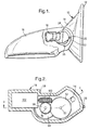
- an exterior mirror has a base member 10 with a mounting surface 12 on one side, for attachment to the left hand front door of a motor car, and a platform 14 projecting laterally from an opposite side.
- a mirror housing 16 is mounted on the platform 14 by a pivotal mounting which allows relative angular movement about a vertical axis, as will be described hereinafter.
- the housing 16 is shown broken away in Figure 1 to reveal a drive unit 18 to which the housing 16 is secured.
- the drive unit 18 has an external finger 20 which engages in an arcuate channel 22 in the base member 10, the ends of such channel 22 serving as stops 24 and 26 to limit the range of angular movement of the housing 16.
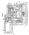
- the drive unit 18 is enclosed in a two-part drive housing comprising a drive housing body 28 and a drive lid 30.
- a cylindrical support member 32 is mounted on the platform 14 and has a clutch disc 34 secured to its upper surface. The upper surface of the clutch disc 34 is frictionally engaged by the annular bottom surface 35 of a cylindrical clutch member 36 which is secured to the bottom surface of the drive housing body 28.
- a generally cylindrical centering bush projects coaxially upwardly from the cylindrical support member 32 and has a square cross-section bottom zone 38, which is a sliding fit in respective correspondingly shaped holes in the clutch disc 34 and the support member 32.
- the square cross-section hole in the support member 32 leads to an enlarged recess 40 in the bottom surface thereof.
- the centering bush 42, 44, 46 has a small-diameter lower cylindrical zone 42, then a cylindrical flange 44, then a large-diameter intermediate cylindrical zone 46 (of smaller diameter than the flange 44), and finally a small-diameter upper cylindrical zone 48 (of diameter between that of the bottom cylindrical zone 42 and that of the intermediate zone 46).
- An arcuate projection 50 is formed on the upper surface of the flange 44 so as to extend radially outwardly from the lower part of the intermediate zone 46 for about 30°.
- the upper zone 48 of the centering bush is a sliding fit in aligned holes in the top part of the clutch member 36 and the bottom of the drive housing body 28 respectively.
- a coupling pin 52 having a threaded bottom end, is a sliding fit in an axial hole in the centering bush.
- the pin 52 has a flange 54 above the upper end of the upper cylindrical zone 48 of the centering bush.
- a first Belleville washer 56 engages between the flange 54 and the inner surface of the bottom of the drive housing body 28.
- a second Belleville washer 60 engages between the inner surface of the recess 40 and a nut 62 which is screwed on to the threaded bottom end of the pin 52.
- the pin 52 is keyed to the centering bush so as to allow the nut 62 to be tightened.
- the force exerted by the two Belleville washers 56 and 60 has the effect of urging the annular bottom surface of the cylindrical clutch member 36 into engagement with the clutch disc 34.
- An annular gear wheel 64 is journalled on the lower cylindrical zone 42 of the centering bush.
- the gear wheel 64 has internal gear teeth 66 on its inner annular surface and has a bottom clutch face 68 which frictionally engages the clutch disc 34 on the support member 32 within the area surrounded by the annular clutch face of the clutch member 36.
- the internal gear teeth 66 are engaged by the lower pinion 70 of a double pinion gear 72 which projects through aligned openings 74 and 76 in the top of the clutch member 36 and the bottom of the drive housing body 28 respectively.
- the gear 72 is journalled on a shaft 78 which has a lower bearing 80 supported by legs 82 and 84 (see also Figure 4) which are formed integrally with the drive housing body 28 and project downwardly from opposite edges of the opening 76 therein, through the opening 74 in the clutch member 36.
- the upper end of the shaft 78 is supported in a bearing 86 formed integrally with the drive lid 30.
- the gear 72 has an upper pinion 88 which is engaged by a lower pinion 90 of a pinion gear which is journalled on the pin 52 above the flange 54 and has an upper pinion 92 on its upper end.
- the upper end of the pin 52 is supported in a bearing 94 formed integrally with the lid 30.
- the pinion 92 is engaged by a lower pinion 96 of a double gear wheel which is journalled on the shaft 74 and has an upper helical gear 98 engaged by a worm gear 100 on the output shaft of an electric motor 102.
- a cam disc 104 is journalled on the flange 44 of the centering bush.
- the upper surface of the cam disc 104 has a raised segment 106 which is joined to the rest of the upper surface by a cam ramp 108 at one end and a step 110 at the other.
- the raised segment 106 projects radially inwardly over the flange 44 and has an arcuate cut-out 112 on its inner annular wall of which receives the arcuate projection 50 so as to restrict the range of angular movement of the cam disc 104 relative to the support member 32.
- the upper surface of the cam disc 104 is engaged by a piston 114 which is slidably mounted in a bore 116 in a raised zone 118 of the bottom of the drive housing body 28.
- the piston 114 is biassed downwardly by a compression spring 120.
- the piston 114 has a sloping face 122 on its bottom end which is inclined at the same angle as the ramp 108 on the cam disc 104.
- the relative forces exerted by the compression spring 120 and the Belleville washers 56 and 60 and the relative areas of the annular clutch face of the clutch member 36 and of the clutch face 68 of the gear wheel 64 are chosen to be such that the force necessary to cause slippage between the clutch disc 34 and the annular gear wheel 64 is greater than the force necessary to cause slippage between the clutch disc 34 and the clutch element 36 but less than the force necessary to cause angular movement of the cam disc 104 to push the piston 114 up the ramp 10.
- the piston 114 has lateral projections 124 and 126 which engage with respective microswitches 128 and 130 of a switch unit 132 which are mounted within the drive housing body 28.
- the microswitches 128 and 130 have changeover contacts which are connected to a manually operable 3-position switch unit 134 having ganged changeover contacts 136 and 138 which are spring-biassed into a central isolating position.
- the operating lever of the switch unit 134 can be displaced either upwardly or downwardly, as viewed in Figure 6, so as to apply a voltage to the motor 102 so as to cause it to rotate in either direction.
- the microswitches 128 and 130 are connected so as to reverse the polarity of the voltage applied to the motor 102 when the piston 114 is displaced upwardly by the ramp 10 on the cam disc 104.
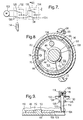
- the switch unit 134 When it is desired to move the mirror housing 16 from its normal position to a parked position in which it is pivoted rearwardly so as to lie against the side of the vehicle body generally behind the base member 10, the switch unit 134 is operated as shown in Figure 7, so as to energise the motor 102 to cause clockwise rotation of the double pinion gear 72. Because the force necessary to cause slippage of the clutch element 36 relative to the clutch disc 34 is less than the force necessary to cause slippage of the annular gear wheel 64 relative to the clutch disc 34, the lower pinion 70 moves in a planetary fashion round the interior of the annular gear wheel 64, causing counter-clockwise annular movement of the drive unit 18 (and with it the mirror housing 16).
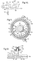
- the switch unit 134 is operated as shown in Figure 10 in order to apply power to the motor 102 with the opposite polarity. This causes counter-clockwise rotation of the pinion 70 so as to cause clockwise planetary movement relative to the annular gear wheel 64 and slippage between the clutch member 36 and the clutch plate 34.
- the mirror housing 16 If the mirror housing 16 is subject to impact from the front, it is displaced towards its parked position, simultaneous slippage taking place between the clutch disc 34 on the one hand and both the clutch element 36 and the clutch face 68 of the annular gear wheel 64 on the other, relative movement between the clutch element 35 and the annular gear wheel 64 being blocked by the worm gear 100.
- the mirror housing 16 can be restored to its normal driving position after such an impact in the same way as it is restored from its parked position.
- the mirror housing 16 If the mirror housing 16 is displaced forwardly as the result of impact from the rear, simultaneous slippage takes place between the clutch disc 34 on the one hand and between both the clutch element 36 and the clutch face 68 of the gear wheel 64 on the other.
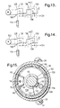
- the piston 114 is displaced upwardly by the ramp 108 on to the raised segment 106 of the cam disc 104, as shown in Figures 11 and 12. Consequently, the microswitches 128 and 130 of the switch unit 132 change state to reverse the polarity of the connections of the motor 102, as illustrated in Figure 13. Forward angular movement of the mirror housing 16 is limited by abutment of the external finger 20 with the stop 22.
- the manual switch unit 134 is operated as shown in Figure 14.
- the effect is that the pinion 70 rotates in the clockwise direction, causing counter-clockwise planetary movement round the planetary gear wheel 64 causing slippage between the clutch disc 34 and the clutch element 36.
- friction between the raised segment 106 of the cam disc 104 and the bottom of the piston 114 causes counter-clockwise angular movement of the cam disc 104 to a position in which the arcuate projection 50 abuts against the end of the cutout 112 further from the ramp 108, as illustrated in Figures 15 and 16.
Landscapes
- Engineering & Computer Science (AREA)
- Multimedia (AREA)
- Mechanical Engineering (AREA)
- Rear-View Mirror Devices That Are Mounted On The Exterior Of The Vehicle (AREA)
Applications Claiming Priority (2)
| Application Number | Priority Date | Filing Date | Title |
|---|---|---|---|
| GB9606461 | 1996-03-27 | ||
| GBGB9606461.3A GB9606461D0 (en) | 1996-03-27 | 1996-03-27 | Exterior rearview mirror for a vehicle |
Publications (3)
| Publication Number | Publication Date |
|---|---|
| EP0798163A2 true EP0798163A2 (de) | 1997-10-01 |
| EP0798163A3 EP0798163A3 (de) | 1998-03-25 |
| EP0798163B1 EP0798163B1 (de) | 2001-10-24 |
Family
ID=10791134
Family Applications (1)
| Application Number | Title | Priority Date | Filing Date |
|---|---|---|---|
| EP19970301664 Expired - Lifetime EP0798163B1 (de) | 1996-03-27 | 1997-03-12 | Fahrzeug-Aussenspiegel |
Country Status (4)
| Country | Link |
|---|---|
| EP (1) | EP0798163B1 (de) |
| JP (1) | JP3866823B2 (de) |
| DE (1) | DE69707540T2 (de) |
| GB (1) | GB9606461D0 (de) |
Cited By (5)
| Publication number | Priority date | Publication date | Assignee | Title |
|---|---|---|---|---|
| EP0879738A2 (de) | 1997-05-24 | 1998-11-25 | Britax (Geco) S.A. | Aussenspiegel für Kraftfahrzeuge |
| ES2166677A1 (es) * | 1999-11-29 | 2002-04-16 | Fico Mirrors Sa | Mecanismo de abatimiento automatico para espejos retrovisores exteriores de vehiculos automoviles. |
| WO2002090149A1 (en) * | 2001-05-03 | 2002-11-14 | Schefenacker Vision Systems Australia Pty Ltd | Compact park mechanism for a vehicle external mirror |
| WO2003086816A1 (en) * | 2002-04-09 | 2003-10-23 | Magna Donnelly Mirrors North America, L.L.C. | Vehicular mirror actuator with single motor actuation |
| NL1025524C2 (nl) * | 2004-02-19 | 2005-08-22 | Iku Holding Montfoort Bv | Spiegelverstelmechanisme, buitenspiegeleenheid en werkwijze. |
Family Cites Families (3)
| Publication number | Priority date | Publication date | Assignee | Title |
|---|---|---|---|---|
| US4981349A (en) * | 1989-09-01 | 1991-01-01 | Kabushiki Kaisha Matsuyama Seisakusho | Rearview mirror assembly for automobiles including positioning means with a recess surface extending uniformly horizontally |
| IT1252140B (it) * | 1991-11-29 | 1995-06-05 | Commer Spa | Dispositivo per la rotazione controllata di uno specchietto retrovisore esterno |
| JP3208994B2 (ja) * | 1994-06-09 | 2001-09-17 | 市光工業株式会社 | 車両用後写鏡装置の駆動装置 |
-
1996
- 1996-03-27 GB GBGB9606461.3A patent/GB9606461D0/en active Pending
-
1997
- 1997-03-12 DE DE1997607540 patent/DE69707540T2/de not_active Expired - Fee Related
- 1997-03-12 EP EP19970301664 patent/EP0798163B1/de not_active Expired - Lifetime
- 1997-03-27 JP JP07482197A patent/JP3866823B2/ja not_active Expired - Fee Related
Cited By (8)
| Publication number | Priority date | Publication date | Assignee | Title |
|---|---|---|---|---|
| EP0879738A2 (de) | 1997-05-24 | 1998-11-25 | Britax (Geco) S.A. | Aussenspiegel für Kraftfahrzeuge |
| US6109755A (en) * | 1997-05-24 | 2000-08-29 | Britax Geco S.A. | Retractable exterior mirror for a motor vehicle |
| ES2166677A1 (es) * | 1999-11-29 | 2002-04-16 | Fico Mirrors Sa | Mecanismo de abatimiento automatico para espejos retrovisores exteriores de vehiculos automoviles. |
| WO2002090149A1 (en) * | 2001-05-03 | 2002-11-14 | Schefenacker Vision Systems Australia Pty Ltd | Compact park mechanism for a vehicle external mirror |
| WO2003086816A1 (en) * | 2002-04-09 | 2003-10-23 | Magna Donnelly Mirrors North America, L.L.C. | Vehicular mirror actuator with single motor actuation |
| NL1025524C2 (nl) * | 2004-02-19 | 2005-08-22 | Iku Holding Montfoort Bv | Spiegelverstelmechanisme, buitenspiegeleenheid en werkwijze. |
| WO2005080136A1 (en) * | 2004-02-19 | 2005-09-01 | Eaton Automotive B.V. | Mirror adjustment mechanism, wing mirror unit and method |
| US7445190B2 (en) | 2004-02-19 | 2008-11-04 | Mci (Mirror Controls International) Netherlands B.V. | Mirror adjustment mechanism, wing mirror unit and method |
Also Published As
| Publication number | Publication date |
|---|---|
| EP0798163B1 (de) | 2001-10-24 |
| JPH106854A (ja) | 1998-01-13 |
| EP0798163A3 (de) | 1998-03-25 |
| JP3866823B2 (ja) | 2007-01-10 |
| GB9606461D0 (en) | 1996-06-05 |
| DE69707540D1 (de) | 2001-11-29 |
| DE69707540T2 (de) | 2002-06-06 |
Similar Documents
| Publication | Publication Date | Title |
|---|---|---|
| AU761386B2 (en) | Wing mirror for vehicle | |
| KR100378506B1 (ko) | 인덱싱 기능 및 제어 피봇 기능을 갖는 외부미러 | |
| KR101147668B1 (ko) | 4 륜 구동의 센터 연결 해제용 전기 액튜에이터 | |
| AU2008203505B2 (en) | Vehicle mirror power fold mechanism | |
| EP2439106B1 (de) | Antriebsklappmechanismus | |
| US6125983A (en) | Electric parking sprag | |
| EP0169245A1 (de) | Ferngesteuerter seitenspiegel für fahrzeuge | |
| US4880274A (en) | Power reclining device of seat | |
| EP0798163B1 (de) | Fahrzeug-Aussenspiegel | |
| WO2002087922A1 (en) | Power fold mechanism for double arm mirrors | |
| US20050105199A1 (en) | Mirror parking mechanism | |
| JP2003028293A (ja) | 車両用変速制御装置 | |
| KR20020010566A (ko) | 미러회전장치 | |
| JP2575365Y2 (ja) | クラッチ機構 | |
| JPH0872613A (ja) | 電動ミラー | |
| JPH0872612A (ja) | 車両用ミラー | |
| JPH0722339Y2 (ja) | サンルーフ用駆動装置 | |
| JPH04178184A (ja) | 駆動装置におけるスイッチ回路 | |
| US6178587B1 (en) | Rotary window cleaner | |
| JPH0512112Y2 (de) | ||
| JPH0558484U (ja) | 電動格納式ドアーミラー | |
| JP2552109Y2 (ja) | 電動式ドアミラー | |
| JP2582083Y2 (ja) | 電動ミラー | |
| JP3057469B2 (ja) | 2方向操作装置 | |
| JPH08156634A (ja) | 推力アクチュエータ |
Legal Events
| Date | Code | Title | Description |
|---|---|---|---|
| PUAI | Public reference made under article 153(3) epc to a published international application that has entered the european phase |
Free format text: ORIGINAL CODE: 0009012 |
|
| AK | Designated contracting states |
Kind code of ref document: A2 Designated state(s): DE FR GB |
|
| PUAL | Search report despatched |
Free format text: ORIGINAL CODE: 0009013 |
|
| AK | Designated contracting states |
Kind code of ref document: A3 Designated state(s): DE FR GB |
|
| 17P | Request for examination filed |
Effective date: 19980727 |
|
| GRAG | Despatch of communication of intention to grant |
Free format text: ORIGINAL CODE: EPIDOS AGRA |
|
| 17Q | First examination report despatched |
Effective date: 20001222 |
|
| GRAG | Despatch of communication of intention to grant |
Free format text: ORIGINAL CODE: EPIDOS AGRA |
|
| GRAH | Despatch of communication of intention to grant a patent |
Free format text: ORIGINAL CODE: EPIDOS IGRA |
|
| GRAH | Despatch of communication of intention to grant a patent |
Free format text: ORIGINAL CODE: EPIDOS IGRA |
|
| GRAA | (expected) grant |
Free format text: ORIGINAL CODE: 0009210 |
|
| AK | Designated contracting states |
Kind code of ref document: B1 Designated state(s): DE FR GB |
|
| REF | Corresponds to: |
Ref document number: 69707540 Country of ref document: DE Date of ref document: 20011129 |
|
| REG | Reference to a national code |
Ref country code: GB Ref legal event code: IF02 |
|
| ET | Fr: translation filed | ||
| PGFP | Annual fee paid to national office [announced via postgrant information from national office to epo] |
Ref country code: FR Payment date: 20020312 Year of fee payment: 6 |
|
| PGFP | Annual fee paid to national office [announced via postgrant information from national office to epo] |
Ref country code: GB Payment date: 20020313 Year of fee payment: 6 |
|
| PGFP | Annual fee paid to national office [announced via postgrant information from national office to epo] |
Ref country code: DE Payment date: 20020327 Year of fee payment: 6 |
|
| PLBE | No opposition filed within time limit |
Free format text: ORIGINAL CODE: 0009261 |
|
| STAA | Information on the status of an ep patent application or granted ep patent |
Free format text: STATUS: NO OPPOSITION FILED WITHIN TIME LIMIT |
|
| 26N | No opposition filed | ||
| PG25 | Lapsed in a contracting state [announced via postgrant information from national office to epo] |
Ref country code: GB Free format text: LAPSE BECAUSE OF NON-PAYMENT OF DUE FEES Effective date: 20030312 |
|
| PG25 | Lapsed in a contracting state [announced via postgrant information from national office to epo] |
Ref country code: DE Free format text: LAPSE BECAUSE OF NON-PAYMENT OF DUE FEES Effective date: 20031001 |
|
| GBPC | Gb: european patent ceased through non-payment of renewal fee |
Effective date: 20030312 |
|
| PG25 | Lapsed in a contracting state [announced via postgrant information from national office to epo] |
Ref country code: FR Free format text: LAPSE BECAUSE OF NON-PAYMENT OF DUE FEES Effective date: 20031127 |
|
| REG | Reference to a national code |
Ref country code: FR Ref legal event code: ST |