EP0798422A2 - Mehrzweck-Ventilstapel - Google Patents
Mehrzweck-Ventilstapel Download PDFInfo
- Publication number
- EP0798422A2 EP0798422A2 EP97101457A EP97101457A EP0798422A2 EP 0798422 A2 EP0798422 A2 EP 0798422A2 EP 97101457 A EP97101457 A EP 97101457A EP 97101457 A EP97101457 A EP 97101457A EP 0798422 A2 EP0798422 A2 EP 0798422A2
- Authority
- EP
- European Patent Office
- Prior art keywords
- hydraulic
- valve
- coupled
- actuator
- hydraulic fluid
- Prior art date
- Legal status (The legal status is an assumption and is not a legal conclusion. Google has not performed a legal analysis and makes no representation as to the accuracy of the status listed.)
- Ceased
Links
Images

Classifications
-
- E—FIXED CONSTRUCTIONS
- E02—HYDRAULIC ENGINEERING; FOUNDATIONS; SOIL SHIFTING
- E02F—DREDGING; SOIL-SHIFTING
- E02F9/00—Component parts of dredgers or soil-shifting machines, not restricted to one of the kinds covered by groups E02F3/00 - E02F7/00
- E02F9/20—Drives; Control devices
- E02F9/22—Hydraulic or pneumatic drives
- E02F9/2264—Arrangements or adaptations of elements for hydraulic drives
- E02F9/2267—Valves or distributors
-
- E—FIXED CONSTRUCTIONS
- E02—HYDRAULIC ENGINEERING; FOUNDATIONS; SOIL SHIFTING
- E02F—DREDGING; SOIL-SHIFTING
- E02F9/00—Component parts of dredgers or soil-shifting machines, not restricted to one of the kinds covered by groups E02F3/00 - E02F7/00
- E02F9/20—Drives; Control devices
- E02F9/22—Hydraulic or pneumatic drives
- E02F9/2278—Hydraulic circuits
- E02F9/2282—Systems using center bypass type changeover valves
-
- E—FIXED CONSTRUCTIONS
- E02—HYDRAULIC ENGINEERING; FOUNDATIONS; SOIL SHIFTING
- E02F—DREDGING; SOIL-SHIFTING
- E02F3/00—Dredgers; Soil-shifting machines
- E02F3/04—Dredgers; Soil-shifting machines mechanically-driven
- E02F3/28—Dredgers; Soil-shifting machines mechanically-driven with digging tools mounted on a dipper- or bucket-arm, i.e. there is either one arm or a pair of arms, e.g. dippers, buckets
- E02F3/30—Dredgers; Soil-shifting machines mechanically-driven with digging tools mounted on a dipper- or bucket-arm, i.e. there is either one arm or a pair of arms, e.g. dippers, buckets with a dipper-arm pivoted on a cantilever beam, i.e. boom
- E02F3/32—Dredgers; Soil-shifting machines mechanically-driven with digging tools mounted on a dipper- or bucket-arm, i.e. there is either one arm or a pair of arms, e.g. dippers, buckets with a dipper-arm pivoted on a cantilever beam, i.e. boom working downwardly and towards the machine, e.g. with backhoes
- E02F3/325—Backhoes of the miniature type
-
- E—FIXED CONSTRUCTIONS
- E02—HYDRAULIC ENGINEERING; FOUNDATIONS; SOIL SHIFTING
- E02F—DREDGING; SOIL-SHIFTING
- E02F3/00—Dredgers; Soil-shifting machines
- E02F3/04—Dredgers; Soil-shifting machines mechanically-driven
- E02F3/96—Dredgers; Soil-shifting machines mechanically-driven with arrangements for alternate or simultaneous use of different digging elements
- E02F3/963—Arrangements on backhoes for alternate use of different tools
- E02F3/964—Arrangements on backhoes for alternate use of different tools of several tools mounted on one machine
-
- E—FIXED CONSTRUCTIONS
- E02—HYDRAULIC ENGINEERING; FOUNDATIONS; SOIL SHIFTING
- E02F—DREDGING; SOIL-SHIFTING
- E02F9/00—Component parts of dredgers or soil-shifting machines, not restricted to one of the kinds covered by groups E02F3/00 - E02F7/00
- E02F9/20—Drives; Control devices
- E02F9/22—Hydraulic or pneumatic drives
- E02F9/2221—Control of flow rate; Load sensing arrangements
-
- E—FIXED CONSTRUCTIONS
- E02—HYDRAULIC ENGINEERING; FOUNDATIONS; SOIL SHIFTING
- E02F—DREDGING; SOIL-SHIFTING
- E02F9/00—Component parts of dredgers or soil-shifting machines, not restricted to one of the kinds covered by groups E02F3/00 - E02F7/00
- E02F9/20—Drives; Control devices
- E02F9/22—Hydraulic or pneumatic drives
- E02F9/2221—Control of flow rate; Load sensing arrangements
- E02F9/2239—Control of flow rate; Load sensing arrangements using two or more pumps with cross-assistance
-
- E—FIXED CONSTRUCTIONS
- E02—HYDRAULIC ENGINEERING; FOUNDATIONS; SOIL SHIFTING
- E02F—DREDGING; SOIL-SHIFTING
- E02F9/00—Component parts of dredgers or soil-shifting machines, not restricted to one of the kinds covered by groups E02F3/00 - E02F7/00
- E02F9/20—Drives; Control devices
- E02F9/22—Hydraulic or pneumatic drives
- E02F9/2278—Hydraulic circuits
- E02F9/2292—Systems with two or more pumps
-
- E—FIXED CONSTRUCTIONS
- E02—HYDRAULIC ENGINEERING; FOUNDATIONS; SOIL SHIFTING
- E02F—DREDGING; SOIL-SHIFTING
- E02F9/00—Component parts of dredgers or soil-shifting machines, not restricted to one of the kinds covered by groups E02F3/00 - E02F7/00
- E02F9/20—Drives; Control devices
- E02F9/22—Hydraulic or pneumatic drives
- E02F9/2278—Hydraulic circuits
- E02F9/2296—Systems with a variable displacement pump
Definitions
- the present invention deals with power machines. More particularly, the present invention deals with the arrangement of valves in a power machine to provide multiple functions.
- the base portion typically supports a house, or operator support portion.
- the house is rotatable relative to the base portion. Rotation is powered by a hydraulic slew motor.
- Mini-excavators also typically have a number of other features.
- a boom is typically coupled to the house.
- a power actuator such as a hydraulic cylinder, is coupled to the boom to pivot the boom relative to the house about an arc substantially located in a vertical plane.
- the boom is also typically pivotable substantially in a horizontal plane. This type of pivoting movement is accomplished through the use of a hydraulic cylinder (referred to as an offset cylinder) coupled to the house and to the boom.
- a hydraulic cylinder referred to as an offset cylinder
- FIG. 2B is a block diagram of a valve stack according to the present invention.
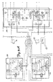
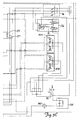
- FIG. 3 is a more detailed schematic diagram of a hydraulic system according to the present invention.
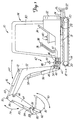
- Base portion 12 also includes a blade 22 which is pivotally coupled to the frame of base portion 12. Blade 22 is also pivotally coupled to a hydraulic cylinder 24 at pivot point 26. Hydraulic cylinder 24 is pivotally coupled to the frame of base portion 12 at pivot point 28. Hydraulic cylinder 24 is selectively provided with hydraulic fluid under pressure from a hydraulic power circuit which is described in greater detail later in the specification. The operator, upon the manipulation of appropriate controls, can raise and lower blade 22 by causing selective retraction and extension of hydraulic cylinder 24.
- Dipper assembly 16 also includes a boom 52.
- Boom 52 is pivotally coupled to bracket 44 at pivot point 54.
- Boom 52 is also pivotally coupled to a hydraulic cylinder 56 at pivot point 58.
- Hydraulic cylinder 56 is, in turn, pivotally coupled to the bracket 44 at pivot point 60.
- boom 52 is raised and lowered through an arc 62 generally defined by a vertical plane.
- Dipper assembly 16 also includes an arm 64 which is pivotally coupled to boom 52 at pivot point 66.
- Arm 64 is also pivotally coupled to a hydraulic cylinder 68 at pivot point 70.
- Hydraulic cylinder 68 is, in turn, pivotally coupled to boom 52 at pivot point 72.
- arm 64 pivots relative to boom 52 through an arc 74 and generally about pivot point 66.
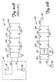
- FIG. 2A shows a portion of a hydraulic circuit (in simplified block diagram form) of a prior mini-excavator.
- FIG. 2A shows a valve stack 92 coupled to a hydraulic fluid supply circuit 94.
- Hydraulic fluid supply circuit 94 is shown in greatly simplified form and includes pump 96 and tank or reservoir 98.
- Valve stack 92 includes relief valve 100, and a plurality of hydraulic actuator valves 102, 104, 106 and 108.
- Valve 102 is a slew valve which controls the flow of hydraulic fluid to the slew motor that causes rotation of operator support portion 14 about base portion 12.
- Valve 104 is a blade valve which controls the flow of hydraulic fluid to hydraulic cylinder 24 in order to manipulate blade 22.
- the slew motor receives substantially all of the hydraulic fluid flow
- the offset actuator 47 receives substantially none of the hydraulic fluid flow. This is because under simultaneous movement of the slew motor and the offset cylinder, inertial force components can act to oppose movement of the offset cylinder such that the amount of pressure required to rotate operator support portion 14 relative to base 12 is significantly less than the amount of pressure required to pivot dipper assembly 16 about axis 48.
- FIG. 2B shows a valve stack 114 according to the present invention in simplified block diagram form.
- Valve stack 114 contains substantially all of the same components as valve stack 92, and those components are similarly numbered. However, the components are configured differently in valve stack 114 than in valve stack 92. Specifically, valve stack 114 has valves 104, 106 and 108 coupled in parallel with one another, while slew valve 102 is coupled in series with the parallel combination of valves 104, 106 and 108. Also, relief valve 100 is moved downstream of valve 102.
- valve 102 Since the slew motor, which is described in greater detail with respect to FIG. 3, is a hydraulic motor, instead of a hydraulic cylinder, hydraulic fluid which is provided to the slew motor through valve 102 is circulated through the slew motor and is returned to valve 102. Therefore, any hydraulic fluid under pressure which is diverted to the slew motor through valve 102 is returned to valve 102 and is provided downstream to the remainder of valves 104-108. Rather than having inlet port 112 of valve 102 plumbed directly to tank 98, the inlet port 112 is provided to the outlet ports 110 of valves 104, 106 and 108, since valves 104, 106 and 108 are connected in parallel with one another.
- valve 102 can now perform the slew function controlled by valve 102 along with any one of the other hydraulic functions controlled by valves 104, 106 or 108.
- valves 104, 106 or 108 For example, if the operator is slewing the operator support portion 14, all of the hydraulic fluid provided to the slew motor is returned to valve stack 114 and also provided to the parallel combination of valves 104, 106 and 108. Therefore, that hydraulic fluid under pressure is still available to perform any of the hydraulic functions performed by those downstream valves.
- the operator is actuating any of the cylinders controlled by valves 104, 106 and 108, and then wants to slew operator support portion 14, the operator can do so substantially without interruption to either the slew operation or the other hydraulic operation previously performed.
- slew motor 102 is provided with its own cross-port relief valves. Therefore, relief valve 100 can be moved downstream of slew valve 102 without jeopardizing the integrity of the relief system in the hydraulic power circuit. Even in the instance in which the cross-port relief valves in the hydraulic slew motor are actuated, the hydraulic fluid under pressure is simply diverted to the low pressure side of the hydraulic slew motor, and the hydraulic fluid is returned to valve 102 and provided downstream to the remainder of valves 104-108.
- valves 102, 104, 106 and 108 are depicted in FIG. 2B as control valves for controlling the slew motor, the blade cylinder, the bucket cylinder and the offset cylinder, the valves can be assigned to control any appropriate or desired hydraulic functions on mini-excavator 10.
- a second valve stack 126 includes bucket valve 106, boom valve 128 which is used to control boom cylinder 56, right hand travel valve 130 which is used to control right hand travel motor 114, left hand travel valve 132 which is used to control left hand travel motor 116, and an auxiliary valve 134 which is used to control one of any number of auxiliary components which can be coupled to valve 134. All of the valves shown in FIG. 3 are depicted in the neutral position but are movable to one of two work positions designated as the A or B positions.
- Pressure reducing valve arrangement 136 reduces the pressure of the hydraulic fluid provided by pumps 96 and provides it to joysticks 40A and 40B. This pressure reduction is necessary to reduce the pressure to an appropriate pilot pressure used to actuate the various valves actuated by joysticks 40A and 40B.
- Tank 98 also has an associated filter and bypass arrangement 138 which includes a fluid filter and a high pressure bypass line. Tank 98 also has an associated hydraulic fluid cooler 140.
- slew valve 102 which controls slew motor 118, is coupled in series with the parallel combination of blade valve 104, boom offset valve 108, arm valve 122 and boost valve 124. Therefore, when slew valve 102 is in the neutral position shown in FIG. 3, the hydraulic fluid under pressure provided by pump 96 simply passes through valve 102 to the parallel combination of valves 104, 108, 122 and 124. However, when the operator manipulates joystick 40B to actuate the slew motor such that valve 102 moves to either position A or position B, hydraulic fluid under pressure is provided through valve 102 to slew motor 118 causing rotation of operator support portion 14 relative to base 12. The direction of rotation depends upon whether valve 102 is in position A or position B.
- valve 102 the hydraulic fluid under pressure provided to slew motor 118 is returned to valve 102 after it circulates through motor 118.
- This hydraulic fluid under pressure is then passed through valve 102 to the parallel combination of valves 104, 108, 122 and 124. Therefore, all of the hydraulic fluid under pressure provided to valve 102, regardless of whether it is diverted to slew motor 118, is available to the parallel combination of valves 104, 108, 122 and 124 for actuation of any of the cylinders associated with those valves.
- FIG. 3 also shows that a similar technique to that used to for valve stack 120 is also used in valve stack 126.
- the hydraulic fluid under pressure provided by pumps 96 is first provided to the valves which control the hydraulic travel motors 114 and 116. Therefore, after the hydraulic fluid travels through motors 114 or 116, it is returned to the appropriate valve 130 and 132 and made available to hydraulic control valves downstream of that valve.
- the hydraulic fluid which is provided from valve 130 to right hand travel motor 114 is returned to valve 130, after it circulates through motor 114, and is made available to boom valve 128 so that the boom cylinder 56 can be actuated while the right hand travel motor 114 is also moving.
- the hydraulic fluid under pressure which is provided through left hand travel valve 132 to left hand travel motor 116 is returned to valve 132, after it circulates through motor 116, and is thus made available to valves 106 and 134 which are located downstream of left hand travel valve 132. Therefore, the bucket cylinder 83, or an auxiliary implement coupled to auxiliary valve 134, can also be actuated even while left hand travel motor 116 is running.
- any excess hydraulic fluid which reaches valve 124 is diverted to the left and right hand travel motors through valves 132 and 130, respectively.
- the hydraulic fluid from boost valve 124 to the left and right hand travel motors is simply provided through a pair of check valves 125 and 127. Therefore, the excess hydraulic fluid reaching boost valve 124 is made available to the travel motors 114 and 116 to increase the travel speed of mini-excavator 10.
- boost valve 124 increases the fluid metering resolution.
- valve spools are stroked. The first is to mechanically push or pull on a tang which protrudes from the valve with a cable or other mechanical linkage. This type of spool is referred to as a manually operated valve spool. The second is to connect a low pressure hydraulic line (the pilot pressure) to stroke the spool hydraulically. This is referred to as a hydraulically actuated spool.
- the valve spools are hydraulically actuated using low pilot pressure from pressure reducing valve 136 through joysticks 40A and 40B.
- boost valve 124 is regulated to actuate at a predetermined pilot pressure, different from the pilot pressure which actuates the boosted valve spools, to achieve desired operation.
- the pilot pressure provided to boom valve 128 in order to initially actuate boom valve 128 may typically be 80 psi. Therefore, when the pilot pressure reaches 80 psi, hydraulic fluid begins to flow out of one of the work ports of valve 128 into either the rod or base of boom cylinder 56.
- boost valve 124 is configured so the pilot pressure to boost valve 124 must be greater than 80 psi before boost valve 124 will begin diverting hydraulic fluid to boom cylinder 56.
- boost cylinder 124 is configured so that it will not begin diverting hydraulic fluid to boom cylinder 56 until the pilot pressure reaches 125 psi.
- both valves open further and provide additional hydraulic fluid to boom cylinder 56. This continues until 300 psi of pilot pressure is provided to boom valve 128 and boost valve 124 at which point both valves are fully stroked and provide full hydraulic fluid under pressure to boom cylinder 56.
Landscapes
- Engineering & Computer Science (AREA)
- Mining & Mineral Resources (AREA)
- Civil Engineering (AREA)
- General Engineering & Computer Science (AREA)
- Structural Engineering (AREA)
- Physics & Mathematics (AREA)
- Fluid Mechanics (AREA)
- Mechanical Engineering (AREA)
- Operation Control Of Excavators (AREA)
- Fluid-Pressure Circuits (AREA)
Applications Claiming Priority (2)
| Application Number | Priority Date | Filing Date | Title |
|---|---|---|---|
| US62316896A | 1996-03-28 | 1996-03-28 | |
| US623168 | 1996-03-28 |
Publications (2)
| Publication Number | Publication Date |
|---|---|
| EP0798422A2 true EP0798422A2 (de) | 1997-10-01 |
| EP0798422A3 EP0798422A3 (de) | 1998-02-04 |
Family
ID=24497045
Family Applications (1)
| Application Number | Title | Priority Date | Filing Date |
|---|---|---|---|
| EP97101457A Ceased EP0798422A3 (de) | 1996-03-28 | 1997-01-30 | Mehrzweck-Ventilstapel |
Country Status (7)
| Country | Link |
|---|---|
| US (1) | US6029446A (de) |
| EP (1) | EP0798422A3 (de) |
| JP (1) | JPH108506A (de) |
| KR (1) | KR970065907A (de) |
| AU (1) | AU720849B2 (de) |
| BR (1) | BR9701407A (de) |
| CA (1) | CA2195818A1 (de) |
Cited By (3)
| Publication number | Priority date | Publication date | Assignee | Title |
|---|---|---|---|---|
| EP0846809A3 (de) * | 1996-12-04 | 1998-09-30 | Clark Equipment Company | Kleinbagger mit verbesserter Ventilanordnung |
| WO2009146009A1 (en) * | 2008-03-31 | 2009-12-03 | Schmidt Stephen T | Tool attachments on an auto-powered mobile machine |
| CN107326957A (zh) * | 2017-08-10 | 2017-11-07 | 曹华诚 | 一种基于离心原理的自我漏水铲斗 |
Families Citing this family (4)
| Publication number | Priority date | Publication date | Assignee | Title |
|---|---|---|---|---|
| FR2822859B1 (fr) * | 2001-03-29 | 2003-07-18 | Volvo Compact Equipment Sa | Engin de travaux publics polyvalent du type chargeuse- pelleteuse |
| US7293494B2 (en) * | 2004-12-23 | 2007-11-13 | Caterpillar Inc. | Expandable hydraulic valve stack |
| US7481052B2 (en) * | 2006-04-17 | 2009-01-27 | Clark Equipment Company | Fluid circuit with multiple flows from a series valve |
| EP2188456A1 (de) * | 2007-08-13 | 2010-05-26 | Clark Equipment Company | Hydraulisches steuersystem für eine schwenkbaumaschine |
Family Cites Families (40)
| Publication number | Priority date | Publication date | Assignee | Title |
|---|---|---|---|---|
| US2322740A (en) * | 1940-06-05 | 1943-06-22 | Sullivan Machinery Co | Hydraulically operated apparatus |
| US3146593A (en) * | 1960-04-18 | 1964-09-01 | Parker Hannifin Corp | Dual pump system and control valve assembly therefor |
| US3279637A (en) * | 1964-09-08 | 1966-10-18 | Robert A Olson | Hydraulic drive control mechanism for vehicles |
| GB1189341A (en) * | 1967-04-08 | 1970-04-22 | Dobson Ltd W E & F | Improvements in or relating to Transportable Load-Carrying Appliances |
| US3550505A (en) * | 1969-05-07 | 1970-12-29 | Gen Signal Corp | Hydraulic system including two work circuits |
| US3922855A (en) * | 1971-12-13 | 1975-12-02 | Caterpillar Tractor Co | Hydraulic circuitry for an excavator |
| US4030623A (en) * | 1971-12-13 | 1977-06-21 | Caterpillar Tractor Co. | Hydraulic circuitry for an excavator |
| JPS5220088Y2 (de) * | 1972-07-15 | 1977-05-10 | ||
| US3960284A (en) * | 1972-10-02 | 1976-06-01 | American Hoist & Derrick Company | Hydraulic backhoe circuitry |
| US3811363A (en) * | 1973-05-10 | 1974-05-21 | Caterpillar Tractor Co | Priority system for series-type hydraulic circuits |
| US3916767A (en) * | 1973-06-14 | 1975-11-04 | Case Co J I | Hydraulic control circuit for vehicles |
| US3910044A (en) * | 1973-08-24 | 1975-10-07 | Case Co J I | Hydraulic summating system |
| FR2250908B3 (de) * | 1973-11-14 | 1977-08-12 | Massey Ferguson Services Nv | |
| DE2440251A1 (de) * | 1974-08-22 | 1976-03-04 | Linde Ag | Schaltung fuer zwei kreislaeufe zur vereinigung der foerderstroeme beider pumpen |
| DE2601484C2 (de) * | 1976-01-16 | 1984-07-26 | Robert Bosch Gmbh, 7000 Stuttgart | Steuereinrichtung für mindestens zwei von einer Druckmittelquelle gespeiste hydraulische Verbraucher |
| US4024710A (en) * | 1976-03-25 | 1977-05-24 | Koehring Company | Load sensing hydraulic circuit having power matching means |
| FR2357764A1 (fr) * | 1976-07-06 | 1978-02-03 | Poclain Sa | Dispositif de commande d'au moins deux organes moteurs a fluide |
| US4023364A (en) * | 1976-07-19 | 1977-05-17 | Caterpillar Tractor Co. | Swing flow supplemental travel for an excavator |
| US4078681A (en) * | 1976-08-24 | 1978-03-14 | Caterpillar Tractor Co. | Dual pump hydraulic control system with predetermined flow crossover provision |
| US4055046A (en) * | 1976-12-22 | 1977-10-25 | Caterpillar Tractor Co. | Control system having override for fluid operated work elements |
| JPS5847109Y2 (ja) * | 1977-10-31 | 1983-10-27 | 株式会社クボタ | バックホウ兼ド−ザ作業車の回路構造 |
| US4256142A (en) * | 1979-08-20 | 1981-03-17 | Hancock Leonard H | Hydraulic control |
| JPS5635806A (en) * | 1979-09-01 | 1981-04-08 | Sanyo Kiki Kk | Compound oil pressure circuit |
| US4343151A (en) * | 1980-05-16 | 1982-08-10 | Caterpillar Tractor Co. | Series - parallel selector for steering and implement |
| JPS6129813Y2 (de) * | 1980-07-07 | 1986-09-02 | ||
| DE3271311D1 (en) * | 1981-03-03 | 1986-07-03 | Hitachi Construction Machinery | Hydrostatic drive system for civil engineering and construction machinery |
| KR870000506B1 (ko) * | 1981-05-02 | 1987-03-12 | 니시모도 후미히라(西元文平) | 토목 건설기계의 유압회로 시스템 |
| JPS584035A (ja) * | 1981-06-27 | 1983-01-11 | Hitachi Constr Mach Co Ltd | 油圧作業機械の油圧回路 |
| JPS5857504A (ja) * | 1981-10-02 | 1983-04-05 | Hitachi Constr Mach Co Ltd | 油圧回路の制御方法 |
| JPS58146631A (ja) * | 1982-02-25 | 1983-09-01 | Hitachi Constr Mach Co Ltd | 油圧作業機械の油圧回路 |
| JPS58146630A (ja) * | 1982-02-25 | 1983-09-01 | Hitachi Constr Mach Co Ltd | 油圧作業機械の油圧回路 |
| JPS592930A (ja) * | 1982-06-29 | 1984-01-09 | Komatsu Ltd | 油圧駆動式作業車両の油圧回路 |
| JPS62107124A (ja) * | 1985-10-15 | 1987-05-18 | Yutani Juko Kk | 建設機械の油圧回路 |
| DE3764824D1 (de) * | 1986-01-25 | 1990-10-18 | Hitachi Construction Machinery | Hydraulisches antriebssystem. |
| JPH078601Y2 (ja) * | 1987-11-10 | 1995-03-01 | 株式会社クボタ | バックホウの油圧回路 |
| JPH01150202U (de) * | 1988-04-08 | 1989-10-17 | ||
| EP0393195B1 (de) * | 1988-06-17 | 1994-01-12 | Kabushiki Kaisha Kobe Seiko Sho | Fluid-steuerungsmechanismus für kraftschaufeln |
| US4986072A (en) * | 1989-08-31 | 1991-01-22 | Kabushiki Kaisha Kobe Seiko Sho | Hydraulic actuator circuit with flow-joining control |
| US5335494A (en) * | 1993-01-21 | 1994-08-09 | Deere & Company | Hydraulic system for reel mower vehicles |
| US5471908A (en) * | 1994-02-16 | 1995-12-05 | Case Corporation | Hydraulic system for backhoe |
-
1997
- 1997-01-20 AU AU12245/97A patent/AU720849B2/en not_active Ceased
- 1997-01-23 CA CA002195818A patent/CA2195818A1/en not_active Abandoned
- 1997-01-30 EP EP97101457A patent/EP0798422A3/de not_active Ceased
- 1997-03-06 KR KR1019970007347A patent/KR970065907A/ko not_active Withdrawn
- 1997-03-21 BR BR9701407A patent/BR9701407A/pt not_active Application Discontinuation
- 1997-03-28 JP JP9078562A patent/JPH108506A/ja active Pending
- 1997-09-25 US US08/937,919 patent/US6029446A/en not_active Expired - Fee Related
Non-Patent Citations (1)
| Title |
|---|
| None |
Cited By (4)
| Publication number | Priority date | Publication date | Assignee | Title |
|---|---|---|---|---|
| US6018895A (en) * | 1996-03-28 | 2000-02-01 | Clark Equipment Company | Valve stack in a mini-excavator directing fluid under pressure from multiple pumps to actuable elements |
| EP0846809A3 (de) * | 1996-12-04 | 1998-09-30 | Clark Equipment Company | Kleinbagger mit verbesserter Ventilanordnung |
| WO2009146009A1 (en) * | 2008-03-31 | 2009-12-03 | Schmidt Stephen T | Tool attachments on an auto-powered mobile machine |
| CN107326957A (zh) * | 2017-08-10 | 2017-11-07 | 曹华诚 | 一种基于离心原理的自我漏水铲斗 |
Also Published As
| Publication number | Publication date |
|---|---|
| JPH108506A (ja) | 1998-01-13 |
| AU1224597A (en) | 1997-10-02 |
| EP0798422A3 (de) | 1998-02-04 |
| BR9701407A (pt) | 1998-07-21 |
| KR970065907A (ko) | 1997-10-13 |
| US6029446A (en) | 2000-02-29 |
| AU720849B2 (en) | 2000-06-15 |
| CA2195818A1 (en) | 1997-09-29 |
Similar Documents
| Publication | Publication Date | Title |
|---|---|---|
| US6018895A (en) | Valve stack in a mini-excavator directing fluid under pressure from multiple pumps to actuable elements | |
| US10900562B2 (en) | Hydraulic system of work machine and work machine | |
| US5832729A (en) | Hydraulic control system | |
| WO2021039283A1 (ja) | 建設機械の油圧システム | |
| US20030089002A1 (en) | Hydraulic systems for small loader | |
| US6029446A (en) | Multifunction valve stack | |
| US6357231B1 (en) | Hydraulic pump circuit for mini excavators | |
| JPH0216416B2 (de) | ||
| JP3076210B2 (ja) | 建設機械の油圧駆動装置 | |
| JP7091046B2 (ja) | 作業機の油圧システム | |
| CN114746612B (zh) | 作业机 | |
| JP3720532B2 (ja) | パワーショベルのアーム作動回路 | |
| US4139066A (en) | Hydraulic tilt and pitch control for dozer blade | |
| JP6973893B2 (ja) | 作業機の油圧システム | |
| US3720332A (en) | Hydraulic systems | |
| JPS58193906A (ja) | 作業機械の油圧回路 | |
| JP2685870B2 (ja) | 作業機械の油圧回路 | |
| JP3664641B2 (ja) | バックホウの油圧装置 | |
| JPH0893000A (ja) | 油圧パイロット操作回路 | |
| JP2002194776A (ja) | バックホウ | |
| JP2001050208A (ja) | 作業機の油圧制御装置 | |
| JPS5961633A (ja) | 油圧作業機の油圧回路 | |
| JP2624268B2 (ja) | 建設機械の油圧駆動装置 | |
| DE2336157C3 (de) | Selbstfahrendes Hub- und Förderfahrzeug für den Erdbau und dergleichen | |
| JPS6145248Y2 (de) |
Legal Events
| Date | Code | Title | Description |
|---|---|---|---|
| PUAI | Public reference made under article 153(3) epc to a published international application that has entered the european phase |
Free format text: ORIGINAL CODE: 0009012 |
|
| AK | Designated contracting states |
Kind code of ref document: A2 Designated state(s): BE DE FR GB IT |
|
| PUAL | Search report despatched |
Free format text: ORIGINAL CODE: 0009013 |
|
| AK | Designated contracting states |
Kind code of ref document: A3 Designated state(s): BE DE FR GB IT |
|
| 17P | Request for examination filed |
Effective date: 19980724 |
|
| 17Q | First examination report despatched |
Effective date: 20010518 |
|
| RTI1 | Title (correction) |
Free format text: EXCAVATING MACHINE WITH A MULTIFUNCTIONAL VALVE STACK |
|
| GRAG | Despatch of communication of intention to grant |
Free format text: ORIGINAL CODE: EPIDOS AGRA |
|
| STAA | Information on the status of an ep patent application or granted ep patent |
Free format text: STATUS: THE APPLICATION HAS BEEN REFUSED |
|
| 18R | Application refused |
Effective date: 20021026 |