EP0800905B1 - Filière d'extrusion pour panneau de mousse rigide - Google Patents
Filière d'extrusion pour panneau de mousse rigide Download PDFInfo
- Publication number
- EP0800905B1 EP0800905B1 EP97104242A EP97104242A EP0800905B1 EP 0800905 B1 EP0800905 B1 EP 0800905B1 EP 97104242 A EP97104242 A EP 97104242A EP 97104242 A EP97104242 A EP 97104242A EP 0800905 B1 EP0800905 B1 EP 0800905B1
- Authority
- EP
- European Patent Office
- Prior art keywords
- die
- lips
- mandrel
- sheet
- melt
- Prior art date
- Legal status (The legal status is an assumption and is not a legal conclusion. Google has not performed a legal analysis and makes no representation as to the accuracy of the status listed.)
- Expired - Lifetime
Links
- 239000006260 foam Substances 0.000 title claims description 37
- 238000001125 extrusion Methods 0.000 title claims description 30
- 238000005187 foaming Methods 0.000 claims description 23
- 239000000155 melt Substances 0.000 claims description 21
- 229920001169 thermoplastic Polymers 0.000 claims description 8
- 239000004416 thermosoftening plastic Substances 0.000 claims description 7
- 230000008859 change Effects 0.000 claims description 6
- 230000001154 acute effect Effects 0.000 claims description 5
- 238000000926 separation method Methods 0.000 claims description 4
- 238000002955 isolation Methods 0.000 claims description 2
- 238000011064 split stream procedure Methods 0.000 claims description 2
- 238000011144 upstream manufacturing Methods 0.000 claims description 2
- 230000013011 mating Effects 0.000 claims 2
- 230000001105 regulatory effect Effects 0.000 claims 1
- 238000000034 method Methods 0.000 description 17
- 230000008569 process Effects 0.000 description 15
- 239000002826 coolant Substances 0.000 description 5
- 239000000463 material Substances 0.000 description 5
- 230000000712 assembly Effects 0.000 description 4
- 238000000429 assembly Methods 0.000 description 4
- 238000001816 cooling Methods 0.000 description 4
- 239000010408 film Substances 0.000 description 4
- 238000004519 manufacturing process Methods 0.000 description 4
- 230000002349 favourable effect Effects 0.000 description 3
- 239000011324 bead Substances 0.000 description 2
- 230000015572 biosynthetic process Effects 0.000 description 2
- 238000010276 construction Methods 0.000 description 2
- 230000009977 dual effect Effects 0.000 description 2
- 239000010410 layer Substances 0.000 description 2
- 229920005989 resin Polymers 0.000 description 2
- 239000011347 resin Substances 0.000 description 2
- 241000239290 Araneae Species 0.000 description 1
- 230000008901 benefit Effects 0.000 description 1
- 238000003490 calendering Methods 0.000 description 1
- 239000012792 core layer Substances 0.000 description 1
- 230000008030 elimination Effects 0.000 description 1
- 238000003379 elimination reaction Methods 0.000 description 1
- 235000012438 extruded product Nutrition 0.000 description 1
- 239000012530 fluid Substances 0.000 description 1
- 239000004088 foaming agent Substances 0.000 description 1
- 239000011796 hollow space material Substances 0.000 description 1
- 230000002452 interceptive effect Effects 0.000 description 1
- 238000012423 maintenance Methods 0.000 description 1
- 239000000203 mixture Substances 0.000 description 1
- 238000012986 modification Methods 0.000 description 1
- 230000004048 modification Effects 0.000 description 1
- 238000000465 moulding Methods 0.000 description 1
- 238000004806 packaging method and process Methods 0.000 description 1
- 239000004033 plastic Substances 0.000 description 1
- 229920003023 plastic Polymers 0.000 description 1
- 229920000642 polymer Polymers 0.000 description 1
- 238000012805 post-processing Methods 0.000 description 1
- 230000008439 repair process Effects 0.000 description 1
- 229920003002 synthetic resin Polymers 0.000 description 1
- 239000000057 synthetic resin Substances 0.000 description 1
- 239000010409 thin film Substances 0.000 description 1
- 230000003313 weakening effect Effects 0.000 description 1
- 239000002023 wood Substances 0.000 description 1
- 239000002983 wood substitute Substances 0.000 description 1
Images


Classifications
-
- B—PERFORMING OPERATIONS; TRANSPORTING
- B29—WORKING OF PLASTICS; WORKING OF SUBSTANCES IN A PLASTIC STATE IN GENERAL
- B29C—SHAPING OR JOINING OF PLASTICS; SHAPING OF MATERIAL IN A PLASTIC STATE, NOT OTHERWISE PROVIDED FOR; AFTER-TREATMENT OF THE SHAPED PRODUCTS, e.g. REPAIRING
- B29C44/00—Shaping by internal pressure generated in the material, e.g. swelling or foaming ; Producing porous or cellular expanded plastics articles
- B29C44/34—Auxiliary operations
- B29C44/36—Feeding the material to be shaped
- B29C44/46—Feeding the material to be shaped into an open space or onto moving surfaces, i.e. to make articles of indefinite length
- B29C44/461—Feeding the material to be shaped into an open space or onto moving surfaces, i.e. to make articles of indefinite length dispensing apparatus, e.g. dispensing foaming resin over the whole width of the moving surface
- B29C44/465—Feeding the material to be shaped into an open space or onto moving surfaces, i.e. to make articles of indefinite length dispensing apparatus, e.g. dispensing foaming resin over the whole width of the moving surface with adjustable die gap
-
- B—PERFORMING OPERATIONS; TRANSPORTING
- B29—WORKING OF PLASTICS; WORKING OF SUBSTANCES IN A PLASTIC STATE IN GENERAL
- B29C—SHAPING OR JOINING OF PLASTICS; SHAPING OF MATERIAL IN A PLASTIC STATE, NOT OTHERWISE PROVIDED FOR; AFTER-TREATMENT OF THE SHAPED PRODUCTS, e.g. REPAIRING
- B29C44/00—Shaping by internal pressure generated in the material, e.g. swelling or foaming ; Producing porous or cellular expanded plastics articles
- B29C44/34—Auxiliary operations
- B29C44/36—Feeding the material to be shaped
- B29C44/46—Feeding the material to be shaped into an open space or onto moving surfaces, i.e. to make articles of indefinite length
- B29C44/461—Feeding the material to be shaped into an open space or onto moving surfaces, i.e. to make articles of indefinite length dispensing apparatus, e.g. dispensing foaming resin over the whole width of the moving surface
-
- B—PERFORMING OPERATIONS; TRANSPORTING
- B29—WORKING OF PLASTICS; WORKING OF SUBSTANCES IN A PLASTIC STATE IN GENERAL
- B29C—SHAPING OR JOINING OF PLASTICS; SHAPING OF MATERIAL IN A PLASTIC STATE, NOT OTHERWISE PROVIDED FOR; AFTER-TREATMENT OF THE SHAPED PRODUCTS, e.g. REPAIRING
- B29C44/00—Shaping by internal pressure generated in the material, e.g. swelling or foaming ; Producing porous or cellular expanded plastics articles
- B29C44/34—Auxiliary operations
- B29C44/36—Feeding the material to be shaped
- B29C44/46—Feeding the material to be shaped into an open space or onto moving surfaces, i.e. to make articles of indefinite length
- B29C44/468—Feeding the material to be shaped into an open space or onto moving surfaces, i.e. to make articles of indefinite length in a plurality of parallel streams which unite during the foaming
-
- B—PERFORMING OPERATIONS; TRANSPORTING
- B29—WORKING OF PLASTICS; WORKING OF SUBSTANCES IN A PLASTIC STATE IN GENERAL
- B29C—SHAPING OR JOINING OF PLASTICS; SHAPING OF MATERIAL IN A PLASTIC STATE, NOT OTHERWISE PROVIDED FOR; AFTER-TREATMENT OF THE SHAPED PRODUCTS, e.g. REPAIRING
- B29C48/00—Extrusion moulding, i.e. expressing the moulding material through a die or nozzle which imparts the desired form; Apparatus therefor
- B29C48/03—Extrusion moulding, i.e. expressing the moulding material through a die or nozzle which imparts the desired form; Apparatus therefor characterised by the shape of the extruded material at extrusion
- B29C48/07—Flat, e.g. panels
-
- B—PERFORMING OPERATIONS; TRANSPORTING
- B29—WORKING OF PLASTICS; WORKING OF SUBSTANCES IN A PLASTIC STATE IN GENERAL
- B29C—SHAPING OR JOINING OF PLASTICS; SHAPING OF MATERIAL IN A PLASTIC STATE, NOT OTHERWISE PROVIDED FOR; AFTER-TREATMENT OF THE SHAPED PRODUCTS, e.g. REPAIRING
- B29C48/00—Extrusion moulding, i.e. expressing the moulding material through a die or nozzle which imparts the desired form; Apparatus therefor
- B29C48/03—Extrusion moulding, i.e. expressing the moulding material through a die or nozzle which imparts the desired form; Apparatus therefor characterised by the shape of the extruded material at extrusion
- B29C48/07—Flat, e.g. panels
- B29C48/08—Flat, e.g. panels flexible, e.g. films
-
- B—PERFORMING OPERATIONS; TRANSPORTING
- B29—WORKING OF PLASTICS; WORKING OF SUBSTANCES IN A PLASTIC STATE IN GENERAL
- B29C—SHAPING OR JOINING OF PLASTICS; SHAPING OF MATERIAL IN A PLASTIC STATE, NOT OTHERWISE PROVIDED FOR; AFTER-TREATMENT OF THE SHAPED PRODUCTS, e.g. REPAIRING
- B29C48/00—Extrusion moulding, i.e. expressing the moulding material through a die or nozzle which imparts the desired form; Apparatus therefor
- B29C48/25—Component parts, details or accessories; Auxiliary operations
- B29C48/255—Flow control means, e.g. valves
- B29C48/2556—Flow control means, e.g. valves provided in or in the proximity of dies
-
- B—PERFORMING OPERATIONS; TRANSPORTING
- B29—WORKING OF PLASTICS; WORKING OF SUBSTANCES IN A PLASTIC STATE IN GENERAL
- B29C—SHAPING OR JOINING OF PLASTICS; SHAPING OF MATERIAL IN A PLASTIC STATE, NOT OTHERWISE PROVIDED FOR; AFTER-TREATMENT OF THE SHAPED PRODUCTS, e.g. REPAIRING
- B29C48/00—Extrusion moulding, i.e. expressing the moulding material through a die or nozzle which imparts the desired form; Apparatus therefor
- B29C48/25—Component parts, details or accessories; Auxiliary operations
- B29C48/30—Extrusion nozzles or dies
- B29C48/305—Extrusion nozzles or dies having a wide opening, e.g. for forming sheets
- B29C48/31—Extrusion nozzles or dies having a wide opening, e.g. for forming sheets being adjustable, i.e. having adjustable exit sections
-
- B—PERFORMING OPERATIONS; TRANSPORTING
- B29—WORKING OF PLASTICS; WORKING OF SUBSTANCES IN A PLASTIC STATE IN GENERAL
- B29C—SHAPING OR JOINING OF PLASTICS; SHAPING OF MATERIAL IN A PLASTIC STATE, NOT OTHERWISE PROVIDED FOR; AFTER-TREATMENT OF THE SHAPED PRODUCTS, e.g. REPAIRING
- B29C48/00—Extrusion moulding, i.e. expressing the moulding material through a die or nozzle which imparts the desired form; Apparatus therefor
- B29C48/25—Component parts, details or accessories; Auxiliary operations
- B29C48/30—Extrusion nozzles or dies
- B29C48/305—Extrusion nozzles or dies having a wide opening, e.g. for forming sheets
- B29C48/31—Extrusion nozzles or dies having a wide opening, e.g. for forming sheets being adjustable, i.e. having adjustable exit sections
- B29C48/313—Extrusion nozzles or dies having a wide opening, e.g. for forming sheets being adjustable, i.e. having adjustable exit sections by positioning the die lips
Definitions
- the present invention relates generally to extrusion apparatus, and more particularly to an extrusion die for rigid foam sheet products.
- thermoplastic products in the higher density ranges, particularly in geographical areas experiencing a shortage of raw wood.
- Such products include decorative moldings and the like, but more particularly larger panels for use as cabinet doors, room doors, furniture, packaging, construction board, and the like.
- rigid foam sheet is intended to refer to any foam sheet which has a hard or firm external skin, whether or not the sheet has a hardened center sheet-like core as is typical of many extruded foam sheet products manufactured by inward-foaming extrusion processes.
- the present invention concerns an extrusion die for use in the continuous manufacture of thermoplastic rigid foam sheet products by a process known as "foaming inwards" or “inward-foaming” foam extrusion.
- the method of "foaming outwards” is an older, simpler method in which a thermoplastic polymer with a foaming agent is extruded through a wide slit.
- the hot, soft, still-foaming extrusion material is led directly to an in-line calibrating facility where the process of expansion of the foam is stopped by contact of the foaming extrudate with a cooled surface.
- a mandrel or "torpedo” is employed in the extrusion die to split the path of the melt and create a hollow space inside the melt into which the melt can foam (hence the term "inward-foaming").
- the outer surfaces of the melt are cooled by a closely following cooled calibrator, forming a skin in which no foaming takes place.
- the melt foams into the hollow formed towards the center of the melt until the hollow is filled and an equilibrium counter pressure is created inside the melt.
- the Celuka inward-foaming process described in the '642 patent is discussed in U.S. patent No. 4,399, 086 to Walter.
- the '086 Walter patent states that by use of the inward-foaming process, the density of the foamed material can be varied by appropriate choice of parameters such as torpedo shape and size, cooling rate and withdrawal rate of the melt, composition of the melt, etc.
- the resulting outer skin is relatively thick, however, and the foamed core layer contains cells widely varying in size, and cell diameter.
- the structure is said by Walter to often be non-homogeneous, in particular in the cross section at the center line where the two inwardly foaming layers meet. "Not infrequently a laminar, linear texture, or even internal separation of the material can be observed at the center line.
- the resultant weakening of the core can be of disadvantage in applications where the sheet is subject to high mechanical stressing and rigidity is especially important.”
- the '086 patent criticizes the inward-foaming process for its inability to produce thin sheets more than 1000 mm wide and less than 10 mm thick, except at great expense. Two reasons are given: 1) it is not possible to create the space in the die with a torpedo which has a very small height to width ratio, and 2) the outer skin cannot be produced thinner than a certain value due to the intensive cooling needed to create the hollow section during calibration.
- the Walter '086 process purports to overcome the problems of the inward-foaming process by a process in which the polymer melt is permitted to foam unrestrained, and is then post-processed by sequential application of cooling and heat to create the desired properties of the resulting foam product.
- the melt passes over the die lips which are oil-cooled to 140 degrees.
- the material then enters a 20 mm precalibrator where the outer edge is cooled so quickly that the melt (PVC) does not have a chance to bubble.
- the lips are of the flexible hinge adjustable type.
- the Milacron die is believed to be capable of producing rigid foam sheet no thinner than 10 mm.
- the Milacron die can handle a very limited range of extrusion slit gauge adjustments due to the use of flexible-hinge-type adjustment lips.
- To make a significant change in sheet gauge with the Milacron die requires effectively disassembling a major part of the die and replacing major components, including the adjustable lips, with consequent down time and component cost burden.
- Flow and pressure control is inadequate to produce acceptable rigid foam sheet product across in a wide range of foam sheet gauges.
- U.S. Patent No. 4,797,083 to Reifenhauser depicts an extrusion die of the inward-foaming type which utilizes an elongated melt-splitting mandrel supported without ribs.
- the elimination of such ribs is said to avoid undesirable texturing of the sheet caused by such ribs and non-uniform foaming in the edge regions of the extruded product.
- Flow control is provided by adjustable flow control members positioned in throttling passages in each of the melt streams.
- US 4 248 579 depicts a film extrusion die for forming transparent, uniformly thick films of synthetic resins.
- the die is a T-shaped extrustion die adapted for forming such films.
- the die depicted has lips forming a slot-like passage for the molten resin, said lips being constructed to adjustably slide toward and away from each other to vary the flow of resin through the passage.
- the die further has a modified inner deckle, support rod, and rod driving device that is said to improve control and uniformity of the thin film thickness.
- the die is also said to eliminate the need for equipment to remove edge beads from the formed film by preventing bead formation.
- the extrusion die of the present invention is capable of producing quality rigid foam sheet product in a wide range of thickness from at least 30 mm to 3 mm or less, thus overcoming the serious small gauge sheet capabilities of prior inward-foaming extrusion dies.
- the extrusion die of the present invention is capable of producing quality rigid foam sheet product in a wide range of thickness from at least 30 mm to 3 mm or less, thus overcoming the serious small gauge sheet capabilities of prior inward-foaming extrusion dies.
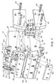
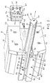
- Figs. 1-3 illustrate an extrusion die 8 for making rigid foam sheet in accordance with the teachings of the present invention, comprising an upper die body 10, a center die body 11 and a lower die body 12.
- the upper die body 10 and center die body 11 define an upper manifold 14.
- the center die body 11 and lower die body 12 define a lower manifold 16.
- the upper and lower manifolds 14, 16 conduct a split stream of heated thermoplastic melt from an extruder (not shown) through separated upper distribution channel 18 and lower distribution channel 20 to a die terminus.
- the nearest surfaces 20, 24 of the upper and lower distribution channels 18, 20, respectively are defined by an intervening mandrel 26.
- the remote surfaces of the upper and lower distribution channels 18, 20 in the terminal region of the die are constituted by the faces 28, 30 of upper lip 32 and lower lip 34, respectively. (See Fig. 3.)
- the mandrel 26 is configured and adapted for quick withdrawal and replacement from an end of the die through a passageway 36 extending through the die 8 transverse to the direction of extrusion of the foam sheet. (The foam sheet is not shown.)
- the passageway 36 formed in the center die body 11 in cross section has a portion 38 (see Fig. 2) which is convergent toward the rear of the die body.
- the mandrel 26 has a configuration in cross-section with a male convergent portion 40 which mates with the female convergent portion 38 of the die body 11, forming a keyway configuration which assures secure and geometrically accurate positioning of the mandrel 26 in the die body when properly located in the passageway 36.
- attachment means such as a series of bolts, one of which is shown at 41, engage the convergent portion 40 of the mandrel 26 through a rear opening 44 in the die body 11. (See Fig. 1.)
- end seal plates 46, 48 are held in place against a gasket 49 by end seal retainer plates 50, 52 which are in turn secured by bolts 42.
- the end seal plates 46, 48 are separated by adjustment screws 47 which are turned to adjust the pressure of end seal plate 48 and gasket 49 against the die body.
- the mandrel 26 can be quickly removed and replaced with a mandrel adapted for a different gauge sheet or different properties, or removed for maintenance and/or repair, by simply removing the end seal plates 46, 48 and sliding the mandrel 26 out of the passageway 36 in the center die body 11.
- the mandrel 26 has a conduit 54 throughout its length for conducting a coolant.
- a coolant supply is coupled to the mandrel 26 by means of a fitting (not shown) connected to the conduit 54 through openings in the end seal plates 48, 50.
- the opening in end seal plate 46 is shown at 56.
- the upper and lower lips 32, 34 are constructed and arranged to adjustably slide toward and away from each other to vary the melt flow in the upper and lower distribution channels 18, 20.
- the upper lip 32 is mounted to slide along an adjustment axis 58 (Fig. 3) by rotational adjustment of a series of like lip adjusting spools 62.
- the spools 62 each comprise a unitary collar-sleeve-nut member 63 which turns on a threaded shaft 64 screwed into a threaded bore in the upper lip 32.
- a series of like lock bolts 67 secure the upper lip 32 firmly against the upper die body 10 when the upper lip 32 has been set to the desired position by adjustment of spools 62.
- the lock bolts 67 can be set to immobilize the lip, or can be set just firmly enough to permit adjustment of the lip without fluid leakage.
- the lower lip 34 is similarly adjustable along an adjustment axis 68 and, like the upper lip 32 described immediately above, is adjustable in position and longitudinal configuration by means of a series of lip adjustment spools, one of which is shown at 70.
- the lower lip 34 is secured in place by a series of like lock bolts 72.
- the upper and lower lips 32, 34 are cooled by introduction of a coolant from a supply (not shown) into conduits 66, 69 in the lips 32, 34 through fittings (not shown) passing through openings 71a, 71b, 73a, 73b in end seal plates 46, 48.
- the openings 71a, 71b, 73a, 73b are angled at the tilt angle 65 of the upper and lower lips 32, 34 to permit the lips to be adjusted without interfering with the coolant fittings.
- the adjustment axes 58, 68 of the adjustable lips 32, 34 are tilted rearwardly at an acute angle relative to an orthogonal to the sheet being formed.
- the adjustment axes 58, 68 of the upper and lower lips 32, 34 are both tilted rearwardly by the same tilt angle 65.
- the tilt angle 65 is preferably between about 10 degrees and 20 degrees to and orthogonal to the foam sheet being extruded. In a die successfully tested, the tilt angle 65 is 15 degrees.
- the face 28 of the upper lip 32 has a forward face portion 74 which is parallel to the sheet being formed, and a rear face portion 76 which forms an acute angle with the plane of the sheet.
- the lower lip 34 has a similar forward face portion 77 and rear face portion 79. This truncation of the rear comers of the adjustable lips 32,34 improves the streamlining of the upper and lower distribution channels 18, 20, particularly when the die is set up to produce small gauge foam sheets.
- Upper and lower precalibration blocks 78, 80 are affixed to the upper lip 32 and lower lip 34, respectively, by means of a series of like bolts, shown at 82 for the block 78, and at 84 for the block 80.
- the precalibration blocks 78, 80 have conduits 86, 88, respectively, formed therein for conducting coolant through the blocks 78, 80.
- the temperature of the precalibration blocks 78, 80 is maintained at a significantly lower temperature than the temperature of the adjustable lips 32, 34.
- recesses are provided in the blocks 78, 80, respectively, to create air gaps between the blocks 78, 80 and lips 32, 34.
- the recess in the lower block 80 is shown at 92.
- the extrusion die 8 includes a pair of adjustable upper and lower restrictor bar assemblies 96, 98 which are adjusted vertically and laterally in concert with vertical and lateral adjustments of the lips 32, 34 in order to control and properly profile the flow of thermoplastic melt in the terminal region of the die 8.
- the restrictor bar assemblies 96, 98 may have a structure which is similar to that found in restrictor bar assemblies for extrusion dies for non-foamed extruded thermoplastic sheet products.
- the upper restrictor bar assembly 96 comprises an upper restrictor bar 100 which is adjustable along a restrictor bar adjustment axis 102 by means of a series of like adjustment spools 104.
- the adjustment spools 104 may be constructed similar to the lip adjustment spools 62, 70 described above for adjusting the lips 32, 34.
- the upper restrictor bar 100 is located upstream of the upper lip 32 and regulates the melt flow in the upper distribution channel 18 in the region adjacent the upper lip 32. It is preferred that the adjustment axis 102 of the upper restrictor bar 100 be tilted rearwardly by the same angle as the tilt angle 65 of the adjustment axis 58 of the upper lip 32 such that the upper lip 32 and the upper restrictor bar 100 move in parallel.
- the lower restrictor bar assembly 96 is preferably constructed similar to the upper restrictor bar assembly 98.
- Fig. 4 illustrates another embodiment of the illustration wherein a mandrel 110 adapted for the manufacture of very thin rigid foam sheet is substituted for the mandrel 26 of the Figs. 1-3 embodiment, as described above.
- the lips 115, 117 are simply readjusted to establish proper process conditions for the new run.
- Fig. 5 depicts yet another embodiment of the illustration wherein a mandrel 114 is employed which is structured to terminate intermediate the forward and rearward ends of the lips.
- the distribution channels 116, 118 defined in part by the mandrel 114 thus merge within the die to create a chamber 120 between the lips 122, 124 within which the melt foams.
- the Fig. 5 embodiment, providing mandrel cooling of the nearest surfaces 126, 128 of the distribution channels 116, 118 only part way through the region of the lips 122, 124, is adapted to produce very thin rigid foam sheets with favorable mechanical properties.
Landscapes
- Engineering & Computer Science (AREA)
- Mechanical Engineering (AREA)
- Manufacturing & Machinery (AREA)
- Extrusion Moulding Of Plastics Or The Like (AREA)
- Molding Of Porous Articles (AREA)
Claims (16)
- Filière (8) pour une feuille de matériau mousse comprenant:des moyens de corps de filière définissant un collecteur comprenant des canaux de distribution séparés (18, 20) pour effectuer un écoulement divisé d'une masse thermoplastique fondue pouvant être amenée à l'état de mousse, chauffée et placée sous pression;une paire de lèvres appariées de filière (32, 34) définissant une sortie de filière rectiligne et disposées sur des côtés opposés des canaux de distribution (18, 20), les lèvres formant au moins en partie une paroi extérieure desdits canaux (18, 20), les lèvres étant agencées de manière à se rapprocher et s'écarter en glissant d'une manière ajustable afin de modifier l'écoulement d'une masse fondue dans les canaux; etun mandrin (26) disposé entre les filières (32, 34) et entre les canaux de distribution séparés, le mandrin (26) pouvant être inséré et retiré, avec possibilité de glissement, dans un passage qui s'étend en travers de la filière, transversalement par rapport à la direction de l'écoulement de la masse fondue dans les canaux de distribution (18, 20) de manière à permettre un retrait et un remplacement rapides du mandrin (26).
- Filière selon la revendication 1, dans laquelle les canaux de distribution séparés définis par les moyens de corps de filière (10, 11, 12) sont configurés de manière à se réunir à l'intérieur de la filière pour créer une chambre de moussage entre les lèvres (32, 34).
- Filière (8) selon la revendication 1, dans laquelle les canaux de distribution séparés traversent les moyens de corps de filière de telle sorte qu'en fonctionnement, une masse fondue est réunie et mousse à l'extérieur de la filière (8).
- Filière selon la revendication 1, dans laquelle les lèvres (32, 34) sont montées chacune de manière à glisser le long d'un axe qui est incliné vers l'arrière sous un angle aigu par rapport à une normale à la feuille devant être formée.
- Filière selon la revendication 1, dans laquelle l'angle est compris entre environ 10 degrés et 20 degrés par rapport à la normale.
- Filière selon la revendication 1, dans laquelle le mandrin (26) est configuré et adapté de manière à permettre un retrait et un remplacement rapides à partir d'une extrémité de la filière (8) par un passage traversant la filière transversalement par rapport à la direction d'extrusion de la feuille, ce qui modifie l'épaisseur d'un produit en forme de feuille devant être extrudé, l'opérateur ayant simplement besoin de changer rapidement le mandrin (26) et d'ajuster la séparation des lèvres (32, 34).
- Filière (8) selon la revendication 1, dans laquelle le mandrin (26) se termine dans une position intermédiaire entre les extrémités avant et arrière des lèvres (32, 34) pour amener les canaux de distribution (18, 20) définies par le mandrin (26) à se réunir à l'intérieur de la filière pour créer une chambre de moussage entre les lèvres (32, 34).
- Filière (8) selon la revendication 1, dans laquelle le mandrin (26) se termine au point de terminaison de la filière (8) de telle sorte que les canaux de distribution (18, 20) sont maintenus séparés dans la filière (8).
- Filière (8) selon la revendication 1, dans laquelle les lèvres (32, 34) possèdent chacune une face venant en contact avec la masse fondue, une partie de face avant étant orientée parallèlement à la feuille et une partie de face arrière faisant un angle aigu avec le plan de la feuille.
- Filière (8) selon la revendication 1, incluant une paire de blocs de préétalonnage adaptés pour être refroidis de manière à faciliter la formation d'une peau sur les surfaces extérieures de la masse fondue, les blocs de préétalonnage étant fixés aux lèvres (32, 34) pour se déplacer avec ces dernières.
- Filière (8) selon la revendication 10, dans laquelle un interstice rempli d'air est formé au niveau d'une interface entre chacun des blocs de préétalonnage et la lèvre, à laquelle le bloc est fixé pour améliorer l'isolation thermique du bloc de préétalonnage vis-à-vis de la lèvre.
- Filière (8) selon la revendication 1, incluant une paire de barres de limitation ajustables, dont l'une est située en amont de chacune des lèvres (32, 34), pour régler la pression et l'écoulement de la masse fondue dans les canaux de distribution séparés (18, 20).
- Filière (8) selon la revendication 12, dans laquelle les lèvres (32, 34) sont montées chacune de manière à glisser le long d'un axe qui est incliné vers l'arrière en faisant un angle aigu par rapport à une normale à la feuille qui est formée.
- Filière (8) selon la revendication 13, dans laquelle les barres de limitation sont montées dans une position contiguë aux lèvres ajustables (32, 34) et sont adaptées pour glisser sur des axes parallèles aux axes de glissement des lèvres.
- Filière (8) selon la revendication 14, dans laquelle les angles de chacun des axes des lèvres et chacun des axes des barres de limitation sont égaux et compris entre environ 10 degrés et 20 degrés par rapport à une normale à la feuille qui est formée.
- Filière (8) selon la revendication 1, dans laquelle le passage en coupe transversale possède une partie qui converge en direction de l'arrière de la filière (8), et dans laquelle le mandrin (26) possède une configuration en coupe transversale appariée, le mandrin (26) étant adapté pour être bloqué rapidement et de façon sûre dans la partie convergente du passage par des moyens de fixation appliqués à partir de l'arrière de la filière (8).
Applications Claiming Priority (2)
| Application Number | Priority Date | Filing Date | Title |
|---|---|---|---|
| US631549 | 1996-04-12 | ||
| US08/631,549 US5770240A (en) | 1996-04-12 | 1996-04-12 | Extrusion die for rigid foam sheet |
Publications (3)
| Publication Number | Publication Date |
|---|---|
| EP0800905A2 EP0800905A2 (fr) | 1997-10-15 |
| EP0800905A3 EP0800905A3 (fr) | 1999-05-12 |
| EP0800905B1 true EP0800905B1 (fr) | 2002-08-28 |
Family
ID=24531695
Family Applications (1)
| Application Number | Title | Priority Date | Filing Date |
|---|---|---|---|
| EP97104242A Expired - Lifetime EP0800905B1 (fr) | 1996-04-12 | 1997-03-13 | Filière d'extrusion pour panneau de mousse rigide |
Country Status (4)
| Country | Link |
|---|---|
| US (1) | US5770240A (fr) |
| EP (1) | EP0800905B1 (fr) |
| JP (1) | JPH1029236A (fr) |
| DE (1) | DE69714897T2 (fr) |
Families Citing this family (11)
| Publication number | Priority date | Publication date | Assignee | Title |
|---|---|---|---|---|
| US6109592A (en) * | 1997-06-16 | 2000-08-29 | Extrusion Dies, Inc. | Flow control device and apparatus for mounting same |
| ITMI20090028A1 (it) * | 2009-01-14 | 2010-07-15 | Afros Spa | Procedimento e dispositivo raffreddato per l'erogazione di miscele poliuretaniche. |
| US8858211B2 (en) | 2011-01-31 | 2014-10-14 | Premier Dies Corporation | Liquid coating die |
| US9216535B2 (en) | 2011-06-07 | 2015-12-22 | 3M Innovative Properties Company | Slot die position adjustments to facilitate patterned products |
| US9044894B2 (en) | 2011-06-07 | 2015-06-02 | 3M Innovative Properties Company | Slot die position adjustment and return to baseline |
| US9579684B2 (en) | 2011-06-07 | 2017-02-28 | 3M Innovative Properties Company | Slot die position adjustment control |
| US9085104B2 (en) | 2011-07-20 | 2015-07-21 | Nordson Corporation | Sculpted extrusion die |
| CN104002459B (zh) * | 2014-05-26 | 2016-03-30 | 安徽中意胶带有限责任公司 | 一种双面四层整芯阻燃输送带复合共挤涂覆模具 |
| JP7284665B2 (ja) * | 2018-11-09 | 2023-05-31 | 芝浦機械株式会社 | Tダイ、tダイ用パッキン、側方密閉機構、およびシート・フィルム製造装置 |
| US12157140B2 (en) * | 2020-08-20 | 2024-12-03 | Lg Energy Solution, Ltd. | Multi-slot die coater |
| IT202300022275A1 (it) * | 2023-10-24 | 2025-04-24 | M Eng S R L Extrusion R Evolution | Testa di estrusione di materiali plastici perfezionata |
Family Cites Families (10)
| Publication number | Priority date | Publication date | Assignee | Title |
|---|---|---|---|---|
| US3680997A (en) * | 1970-06-29 | 1972-08-01 | Pennwalt Corp | Extrusion strip die for thermoplastic sheet |
| US3870451A (en) * | 1973-04-30 | 1975-03-11 | Beloit Corp | Apparatus for extruding foamed thermoplastic material |
| FR2343581A1 (fr) * | 1976-03-10 | 1977-10-07 | Beghin Say Sa | Dispositif de filiere pour la production de feuilles ou pellicules composites |
| US4302172A (en) * | 1980-05-15 | 1981-11-24 | Leesona Corporation | Extrusion die assembly |
| DE3600396A1 (de) * | 1985-11-09 | 1987-05-14 | Reifenhaeuser Masch | Breitschlitzduesenwerkzeug zum strangpressen von mehrschichtigen laminaten aus thermoplastischem kunststoff |
| IT1215422B (it) * | 1986-05-13 | 1990-02-08 | Reifenhaeuser Masch | Trafila per l'estrusione di un nastro di materia plastica del tipo termoplastico espanso. |
| IT1230130B (it) * | 1989-04-28 | 1991-10-14 | Brabor Srl | Testa di estrusione per materiale espanso, in particolare per materiale espanso a base di polivinilcloruro |
| US5045259A (en) * | 1990-03-14 | 1991-09-03 | The Dow Chemical Company | Extrusion of vinylidene chloride copolymers under inert atmosphere |
| US5284430A (en) * | 1991-08-27 | 1994-02-08 | Reynolds Consumer Products, Inc. | Apparatus for manufacture of integral reclosable bag |
| US5259747A (en) * | 1992-04-30 | 1993-11-09 | The Cloeren Company | Web thickness control |
-
1996
- 1996-04-12 US US08/631,549 patent/US5770240A/en not_active Expired - Fee Related
-
1997
- 1997-03-13 EP EP97104242A patent/EP0800905B1/fr not_active Expired - Lifetime
- 1997-03-13 DE DE69714897T patent/DE69714897T2/de not_active Expired - Fee Related
- 1997-04-10 JP JP9092000A patent/JPH1029236A/ja active Pending
Also Published As
| Publication number | Publication date |
|---|---|
| DE69714897T2 (de) | 2003-04-30 |
| EP0800905A2 (fr) | 1997-10-15 |
| JPH1029236A (ja) | 1998-02-03 |
| US5770240A (en) | 1998-06-23 |
| EP0800905A3 (fr) | 1999-05-12 |
| DE69714897D1 (de) | 2002-10-02 |
Similar Documents
| Publication | Publication Date | Title |
|---|---|---|
| JP2798687B2 (ja) | ローラ・ヘッド装置 | |
| EP0668143B1 (fr) | Matrice d'extrusion avec deux lèvres flexibles | |
| US5770240A (en) | Extrusion die for rigid foam sheet | |
| US3680997A (en) | Extrusion strip die for thermoplastic sheet | |
| Kostic et al. | Design of extrusion dies | |
| US5149481A (en) | Method of manufacturing thermoplastic sheet or film | |
| US20080272523A1 (en) | Manufacturing apparatus and manufacturing method for tubular resin film | |
| US20070013100A1 (en) | Method for producing plastic film | |
| CA1230718A (fr) | Plaque-valve et bloc d'apport pour co-extrudeuse, et fonctionnement de l'ensemble | |
| EP2830852B1 (fr) | Collecteur à zone de transition variable | |
| CA1066468A (fr) | Filiere pour l'extrusion de materiaux en feuilles | |
| US3125620A (en) | Process for providing improved surface | |
| US4292019A (en) | Extruded plastic foam shaping apparatus | |
| US3941550A (en) | Apparatus using solid insulating material as a center plate between multiple flat extrusion streams | |
| KR102144770B1 (ko) | 시트/필름의 롤 성형 장치 및 롤 성형 방법 | |
| CA2514919C (fr) | Equipement de fabrication de film en resine tubulaire | |
| KR100620290B1 (ko) | 발포 열가소성 수지 시이트의 제조방법 | |
| US3941551A (en) | Apparatus involving a centerplate and a heat sink between multiple flat extrusion streams | |
| CA2280649A1 (fr) | Systeme d'extrusion de revetement de comptoir a ame de mousse | |
| US6645406B1 (en) | Differential velocity extrusion | |
| JP3654697B2 (ja) | スキン層を有する熱可塑性樹脂発泡シートの製造方法 | |
| JP2000263635A (ja) | 押出成形用サイジング装置 | |
| US20040121132A1 (en) | Differential velocity extrusion | |
| JP2002210807A (ja) | 新規の押出発泡成形ダイ及びこれを用いた発泡成形品の製造方法 | |
| CA3200654A1 (fr) | Dispositif de formation de mousse et appareil d'extrusion de mousse |
Legal Events
| Date | Code | Title | Description |
|---|---|---|---|
| PUAI | Public reference made under article 153(3) epc to a published international application that has entered the european phase |
Free format text: ORIGINAL CODE: 0009012 |
|
| AK | Designated contracting states |
Kind code of ref document: A2 Designated state(s): BE CH DE FR GB IT LI NL SE |
|
| PUAL | Search report despatched |
Free format text: ORIGINAL CODE: 0009013 |
|
| AK | Designated contracting states |
Kind code of ref document: A3 Designated state(s): BE CH DE FR GB IT LI NL SE |
|
| 17P | Request for examination filed |
Effective date: 19991028 |
|
| 17Q | First examination report despatched |
Effective date: 20001213 |
|
| GRAG | Despatch of communication of intention to grant |
Free format text: ORIGINAL CODE: EPIDOS AGRA |
|
| GRAG | Despatch of communication of intention to grant |
Free format text: ORIGINAL CODE: EPIDOS AGRA |
|
| GRAH | Despatch of communication of intention to grant a patent |
Free format text: ORIGINAL CODE: EPIDOS IGRA |
|
| GRAH | Despatch of communication of intention to grant a patent |
Free format text: ORIGINAL CODE: EPIDOS IGRA |
|
| GRAA | (expected) grant |
Free format text: ORIGINAL CODE: 0009210 |
|
| AK | Designated contracting states |
Kind code of ref document: B1 Designated state(s): BE CH DE FR GB IT LI NL SE |
|
| REG | Reference to a national code |
Ref country code: GB Ref legal event code: FG4D |
|
| REG | Reference to a national code |
Ref country code: CH Ref legal event code: EP |
|
| REF | Corresponds to: |
Ref document number: 69714897 Country of ref document: DE Date of ref document: 20021002 |
|
| REG | Reference to a national code |
Ref country code: CH Ref legal event code: NV Representative=s name: E. BLUM & CO. PATENTANWAELTE |
|
| ET | Fr: translation filed | ||
| PG25 | Lapsed in a contracting state [announced via postgrant information from national office to epo] |
Ref country code: GB Free format text: LAPSE BECAUSE OF NON-PAYMENT OF DUE FEES Effective date: 20030313 |
|
| PG25 | Lapsed in a contracting state [announced via postgrant information from national office to epo] |
Ref country code: SE Free format text: LAPSE BECAUSE OF NON-PAYMENT OF DUE FEES Effective date: 20030314 |
|
| PG25 | Lapsed in a contracting state [announced via postgrant information from national office to epo] |
Ref country code: LI Free format text: LAPSE BECAUSE OF NON-PAYMENT OF DUE FEES Effective date: 20030331 Ref country code: CH Free format text: LAPSE BECAUSE OF NON-PAYMENT OF DUE FEES Effective date: 20030331 Ref country code: BE Free format text: LAPSE BECAUSE OF NON-PAYMENT OF DUE FEES Effective date: 20030331 |
|
| PLBE | No opposition filed within time limit |
Free format text: ORIGINAL CODE: 0009261 |
|
| STAA | Information on the status of an ep patent application or granted ep patent |
Free format text: STATUS: NO OPPOSITION FILED WITHIN TIME LIMIT |
|
| 26N | No opposition filed |
Effective date: 20030530 |
|
| BERE | Be: lapsed |
Owner name: *EXTRUSION DIES INC. Effective date: 20030331 |
|
| PG25 | Lapsed in a contracting state [announced via postgrant information from national office to epo] |
Ref country code: NL Free format text: LAPSE BECAUSE OF NON-PAYMENT OF DUE FEES Effective date: 20031001 Ref country code: DE Free format text: LAPSE BECAUSE OF NON-PAYMENT OF DUE FEES Effective date: 20031001 |
|
| EUG | Se: european patent has lapsed | ||
| GBPC | Gb: european patent ceased through non-payment of renewal fee |
Effective date: 20030313 |
|
| REG | Reference to a national code |
Ref country code: CH Ref legal event code: PL |
|
| PG25 | Lapsed in a contracting state [announced via postgrant information from national office to epo] |
Ref country code: FR Free format text: LAPSE BECAUSE OF NON-PAYMENT OF DUE FEES Effective date: 20031127 |
|
| NLV4 | Nl: lapsed or anulled due to non-payment of the annual fee |
Effective date: 20031001 |
|
| REG | Reference to a national code |
Ref country code: FR Ref legal event code: ST |
|
| PG25 | Lapsed in a contracting state [announced via postgrant information from national office to epo] |
Ref country code: IT Free format text: LAPSE BECAUSE OF NON-PAYMENT OF DUE FEES;WARNING: LAPSES OF ITALIAN PATENTS WITH EFFECTIVE DATE BEFORE 2007 MAY HAVE OCCURRED AT ANY TIME BEFORE 2007. THE CORRECT EFFECTIVE DATE MAY BE DIFFERENT FROM THE ONE RECORDED. Effective date: 20050313 |