EP0800918B1 - Zylinderreinigungsvorrichtung und Vorrichtung zur Ablage des Reinigungstuches - Google Patents
Zylinderreinigungsvorrichtung und Vorrichtung zur Ablage des Reinigungstuches Download PDFInfo
- Publication number
- EP0800918B1 EP0800918B1 EP19970105784 EP97105784A EP0800918B1 EP 0800918 B1 EP0800918 B1 EP 0800918B1 EP 19970105784 EP19970105784 EP 19970105784 EP 97105784 A EP97105784 A EP 97105784A EP 0800918 B1 EP0800918 B1 EP 0800918B1
- Authority
- EP
- European Patent Office
- Prior art keywords
- cleaning fabric
- cleaning
- container
- roll
- fabric
- Prior art date
- Legal status (The legal status is an assumption and is not a legal conclusion. Google has not performed a legal analysis and makes no representation as to the accuracy of the status listed.)
- Expired - Lifetime
Links
- 238000004140 cleaning Methods 0.000 title claims description 599
- 239000004744 fabric Substances 0.000 title claims description 516
- 244000208734 Pisonia aculeata Species 0.000 claims description 17
- 230000009471 action Effects 0.000 claims description 15
- 230000000903 blocking effect Effects 0.000 claims description 13
- 238000003825 pressing Methods 0.000 claims description 8
- 230000001965 increasing effect Effects 0.000 claims description 7
- 230000007246 mechanism Effects 0.000 description 28
- 230000003405 preventing effect Effects 0.000 description 22
- 238000010276 construction Methods 0.000 description 20
- 230000004048 modification Effects 0.000 description 9
- 238000012986 modification Methods 0.000 description 9
- 239000003599 detergent Substances 0.000 description 8
- 230000008859 change Effects 0.000 description 6
- 239000000463 material Substances 0.000 description 5
- 239000002184 metal Substances 0.000 description 5
- 238000000034 method Methods 0.000 description 5
- 238000001514 detection method Methods 0.000 description 3
- 239000013013 elastic material Substances 0.000 description 3
- 238000007645 offset printing Methods 0.000 description 3
- 230000003287 optical effect Effects 0.000 description 3
- 230000009467 reduction Effects 0.000 description 3
- 230000008901 benefit Effects 0.000 description 2
- 238000010586 diagram Methods 0.000 description 2
- 230000000694 effects Effects 0.000 description 2
- 230000014759 maintenance of location Effects 0.000 description 2
- 239000007779 soft material Substances 0.000 description 2
- 229920003002 synthetic resin Polymers 0.000 description 2
- 239000000057 synthetic resin Substances 0.000 description 2
- 238000005452 bending Methods 0.000 description 1
- 230000008878 coupling Effects 0.000 description 1
- 238000010168 coupling process Methods 0.000 description 1
- 238000005859 coupling reaction Methods 0.000 description 1
- 238000001035 drying Methods 0.000 description 1
- 230000002708 enhancing effect Effects 0.000 description 1
- 238000000605 extraction Methods 0.000 description 1
- 230000006872 improvement Effects 0.000 description 1
- 239000007788 liquid Substances 0.000 description 1
- 235000011837 pasties Nutrition 0.000 description 1
- 239000002985 plastic film Substances 0.000 description 1
- 229920006255 plastic film Polymers 0.000 description 1
- 238000002360 preparation method Methods 0.000 description 1
- 238000007639 printing Methods 0.000 description 1
- 229920006395 saturated elastomer Polymers 0.000 description 1
- 238000005728 strengthening Methods 0.000 description 1
- 238000004804 winding Methods 0.000 description 1
- 230000037303 wrinkles Effects 0.000 description 1
Images


Classifications
-
- B—PERFORMING OPERATIONS; TRANSPORTING
- B41—PRINTING; LINING MACHINES; TYPEWRITERS; STAMPS
- B41F—PRINTING MACHINES OR PRESSES
- B41F35/00—Cleaning arrangements or devices
-
- B—PERFORMING OPERATIONS; TRANSPORTING
- B41—PRINTING; LINING MACHINES; TYPEWRITERS; STAMPS
- B41P—INDEXING SCHEME RELATING TO PRINTING, LINING MACHINES, TYPEWRITERS, AND TO STAMPS
- B41P2235/00—Cleaning
- B41P2235/10—Cleaning characterised by the methods or devices
- B41P2235/20—Wiping devices
- B41P2235/24—Wiping devices using rolls of cleaning cloth
- B41P2235/246—Pressing the cleaning cloth against the cylinder
Definitions
- the present invention relates to a cylinder cleaning device for cleaning a surface of a cylinder such as a blanket cylinder of an offset printing machine, an impression cylinder or an ink roller. More particularly, the invention relates to a cylinder cleaning device in which a cleaning fabric supply element is made in a roll form, or folded in a pleated form (or folded in zigzags), or a container holding the cleaning fabric supply element.
- a cleaning fabric as used, is wrapped around a hollow core to form a cleaning fabric roll, into which a shaft made of metal is inserted.
- This metal shaft in the cleaning unit as a rotary shaft.
- This arrangement has been widely used.
- a method of directly holding a core to make it a rotary shaft without using such metal shaft has been proposed in Japanese Patent Laid-Open No. 234659/1992 and in EP-A-0 479 403.
- An object of the present invention is to provide a cylinder cleaning device which is enabled either by thinning a roll core extremely or by using no roll core to improve the space efficiency (or space factor) of a cleaning fabric supply element and to use the cleaning fabric supply element held by a container while being small-sized.
- a cylinder cleaning device for cleaning an outer surface of a cylinder by pressing a cleaning fabric supplied from a cleaning fabric supply element against an outer surface of said cylinder, comprising: a frame; and a cleaning fabric supply element container supported on said frame; and a cleaning fabric take-up shaft attached to the frame for taking up used cleaning fabric, forming thereby a cleaning fabric take up roll, wherein the cleaning fabric take-up shaft is arranged within a range to interfere with the container when the diameter of the cleaning fabric take-up roll increases, and wherein the container includes a structure whose shape is physically changed in a direction of increasing diameter of the cleaning fabric take-up roll.
- the cleaning fabric can be easily handled, i.e., attached and detached.
- the device can be made compact by arranging the cleaning fabric take-up shaft within the range in which the cleaning fabric take-up roll interferes with the container. It is also possible to use cleaning fabric rolls or cleaning fabric supply elements of various shapes or core sizes. Moreover, the various cleaning fabric supply elements can be used merely by slightly remedying the various types of conventional cleaning device, which has already been installed.
- the cleaning fabric supply element is held in a reluctantly deformable and rigid container (e.g., a cassette or cartridge) or a deformable container a film material (including a container packaged with the film material), and the container is supported as it is, so that the handling of the cleaning fabric supply element is improved.
- a reluctantly deformable and rigid container e.g., a cassette or cartridge
- a deformable container a film material including a container packaged with the film material
- the cleaning fabric can be prevented from volatilizing or drying by the container to suppress the reduction in the performance of the cleaning fabric, so that it can be easily handled. This effect is enhanced by holding the cleaning fabric using a highly volatile detergent in the container.
- the amount of detergent to be introduced into or applied to the cleaning fabric is so high that the detergent can be prevented from leaking out of even the cleaning fabric impregnated in a saturated state and can be confined in the container.
- the cleaning fabric as supplied from the cleaning fabric supply element, can be partially drawn back to the cleaning fabric supply side and used again as a new one to improve the using efficiency of the cleaning fabric and to lower the cleaning cost and spare the resources.
- the cleaning fabric When the cleaning fabric is pressed onto the cylinder surface, a dragging force in the rotational direction of the cylinder acts upon the cleaning fabric, and this force may draw out the cleaning fabric from the cleaning fabric supply element.
- the cleaning fabric can be braked by the brake means to overcome the dragging force so that it can be prevented from being drawn out.
- cleaning fabric tensioning means moreover, there can be achieved the following advantage. If the cleaning fabric is slack, a wrinkle is formed in the cylinder pressing portion so that the cleaning fabric may not be uniformly pressed onto the cylinder surface to cause an non-homogeneous cleaning operation. With the slackness, on the other hand, the slack portion may come into contact to blot the cylinder surface or may be taken up on the cylinder, when it is not in the cleaning operation. These drawbacks can be eliminated by tensioning the cleaning fabric by the tensioning means.
- a cylinder cleaning device for cleaning the outer surface of a cylinder by pressing a cleaning fabric supplied from a cleaning fabric supply element against said outer surface of said cylinder, comprising: a frame; a receiving member attached to the frame for receiving the outer surface of the cleaning fabric supply element; a first guide member extending longitudinally of the receiving member; and a second guide member extending longitudinally of the receiving member and pairing the first guide member, wherein the first guide member and the second guide member define an S-shaped passage in-between for allowing the cleaning fabric to pass there through.
- the cleaning fabric can be stably supplied by causing it to pass through the S-shaped passage, as defined by the two guide members, from the state, in which it is received by the cleaning fabric supply element, to apply the braking action thereto and by causing it to pass through a predetermined portion near the cleaning fabric supporting receiver.
- the roll core or the diametrically reduced cleaning fabric roll is blocked, when intensively forced to come out from the cleaning fabric supporting receiver, from disengaging out by the S-shaped passage so that the roll core or the cleaning fabric roll can be accidentally wrapped by the cylinder to damage the cylinder.
- the strength of the cleaning unit can be enhanced to support the cleaning fabric supporting receiver stably and reliably.
- the braking action on the cleaning fabric can be increased by the two S-shaped passages while further enhancing the disengagement preventing effect.
- the passage of the cleaning fabric can be widely opened by turning the arm.
- the introduction of the cleaning fabric into the S-shaped passage is completed by letting off the cleaning fabric from the received cleaning fabric roll to the outside of the other guide member, by returning the turned guide member to thread the cleaning fabric into the clearance between the returned guide member and the other guide member, so that the threading work of the cleaning fabric can be facilitated.
- One guide member is turned across the open portion of the cleaning fabric supporting receiver to be charged with the cleaning fabric roll, so that it is positioned at the position opposite to the non-turned other guide member across the cleaning fabric supporting receiver.
- the cleaning fabric roll can be introduced without being hindered by the turned guide member into the cleaning fabric supporting receiver so that the charging work can be facilitated.
- the charging operation can be performed with an excellent workability by turning the cleaning fabric supporting receiver as a whole without being disengaged from the cleaning unit thereby to open the inlet side of the cleaning fabric supply element widely.
- the urging means for urging the guide member When there is provided the urging means for urging the guide member, an intense braking action can be applied to the cleaning fabric so that the cleaning fabric can be highly tensioned and reliably prevented from becoming slack.
- this cover member can be opened to introduce the cleaning fabric supply element to be charged, without disengaging the cleaning fabric supporting receiver from the cleaning unit, so that the workability can be improved.
- the cleaning fabric supply element can be introduced without disengaging the cleaning fabric supporting receiver from the cleaning unit.
- the take-up shaft is arranged in the proximity to the movable member so that the cleaning unit can be small-sized.
- the movable member When the movable member is hinged to the side of the cleaning fabric guide member, the movable member moves according to the change in the diameter of the cleaning fabric roll to move the cleaning fabric roll toward the cleaning fabric guide portion so that the direction to let off the cleaning fabric from the cleaning fabric roll is hardly changed with respect to the cleaning fabric guide portion thereby to stabilize the letting-off of the cleaning fabric.
- the disengagement preventing means for blocking the core having the wrapped cleaning fabric and the diametrically reduced cleaning fabric roll from disengaging out the safety of the cleaning work of the cylinder can be enhanced to prevent the damage of the cylinder in advance thereby to enhance the reliability of the device.
- a cleaning fabric receiving device for receiving a cleaning fabric supply element and for being mounted to a cylinder cleaning device, comprising: a mounting member including end plates and a spindle; a receiving member coupled to the mounting member for receiving the outer surface of the cleaning fabric supply element; a guide member extending longitudinally of said receiving member and define an S-shaped passage in-between for allowing the cleaning fabric to pass there through, and wherein the spindle of said mounting member is attached for use to the frame of said cylinder cleaning device.
- the present invention can be applied as an adapter without any changing work to the existing device of the type using a cleaning fabric supply element.
- the cleaning fabric supply element can have any form such as a rolled form or a folded pleated form (i.e., folded in zigzags). Cleaning fabric rolls with a round-formed roll core or a rod-formed roll core or without any roll core can also be used.
- the cleaning fabric can be made of ordinary fabric, an unwoven fabric, paper, a plastic film with or without processing, or other suitable materials. Processed cleaning fabrics include, for example, fabric previously impregnated with a detergent, fabric packaged in a vacuum pack, and fabric to which a detergent in a jellied form or a paste form has been applied.
- Fig. 1 is a sectional view showing a construction of the cylinder cleaning device of the present invention.
- Fig. 2 shows the construction showing a cleaning unit from the back side with cleaning fabric being removed.
- the cylinder cleaning device which has a container holding a cleaning fabric roll 30 as a cleaning fabric supply element 3.
- the cylinder cleaning device is constructed as a cleaning unit 2 to be mounted to face a cylinder of a press.
- This cleaning unit 2 is constructed to include: a cleaning fabric supporting receiver 4 for receiving the container holding the cleaning fabric roll 30; cleaning fabric advancing means 7 for pull-out a cleaning fabric 3a from the cleaning fabric roll 30; and a cylinder pressing part 8 for pressing the cleaning fabric 3a, as tensioned between the cleaning fabric supporting receiver 4 and the cleaning fabric advancing means 7, onto the surface of the cylinder 1.
- the cleaning fabric advancing means 7 is constructed to include a cleaning fabric take-up shaft 27 and the drive unit (not-shown) such as a motor or an air cylinder for rotating the shaft 27, so that it supplies the cleaning fabric 3a from the cleaning fabric roll 30 by taking up the used cleaning fabric on the cleaning fabric take-up shaft 27.
- a pressure pad 8a forming the cylinder pressing part 8 is supported by a supporting bar 10 which constructs a crossbeam member laid across side plates 9 arranged on both sides of the cleaning unit 2.
- the cleaning fabric supporting receiver 4 as made of a container having a rigidity, is equipped with end plates 11 which are supported by the side frames 9.
- a cover 12 which is opened to introduce the cleaning fabric roll 30 into the container.
- the cleaning fabric 3a is drawn out from a slit exit 15 which is formed between the free end of the cover 12 and the end portion of a stationary plate 14.
- the exit 15 is defined by an S wrap winding passage which is formed between the cover 12 and the stationary plate 14 by causing the end portions of the cover 12 and the stationary plate 14 to overlap each other.
- the cleaning fabric 3a is drawn out while meandering in the passage, as shown. At this time, the cleaning fabric 3a is braked and tensioned by the friction with the end portions of the two members.
- the cover 12 in order to effect the braking action, the cover 12 is urged to move toward the stationary plate 14 by a spring 16. As a result, the cover is forced to abut against the cleaning fabric 3a, as drawn out by the take-up action of the cleaning fabric advancing means 7, to increase the friction with the cleaning fabric.
- a bottom member 17 of the container is turnably attached at its one end side to the pin 13 shared with the cover 12 and is received at its other end side by a receiving bar 18 which is fixed on the side plate 9.
- the bottom member 17 may be any if it can mount the cleaning fabric supplying element 3 thereon.
- a forked member or a net member, for example, can be applied to the bottom member 17.
- a supporting unit 6 for mounting the cleaning fabric supporting receiver 4 on the side plate 9 is equipped with an irrotational shaft such as a spindle 20 having a square section at one end plate 11 (as located at the right-hand end plate in Fig. 2).
- An engaging hole 21 is formed in the other end plate 11 (as located at the left-hand end plate in Fig. 2).
- a fitting hole 22 for fitting the spindle 20 is formed in one side plate 9.
- An engaging member 23 for engaging with the engaging hole 21 is so formed in the other side plate 9 as to rotate and move toward the end plate.
- the cleaning fabric supporting receiver 4 is positioned as the ball 25 comes into the annular groove 24 of the engaging member 23.
- the annular groove 24, the ball 25 and the spring 26 of the engaging member construct a click mechanism.
- the cleaning fabric advancing means 7 is composed of the cleaning fabric take-up shaft 27 and a drive unit 28 such as a motor for rotating the shaft 27.
- the cleaning fabric 3a is supplied from the cleaning fabric roll 30 by taking up the used cleaning fabric on the cleaning fabric take-up shaft 27.
- the braking unit is disposed on the outer circumference of a rear end portion 10a of the supporting bar 10, which is extended apart from the pressure pad 8a, and at the exit 15 of the container.
- the cleaning fabric 3a as drawn out from the container, is taken up by the cleaning fabric take-up shaft 27 by bringing it around the rear end portion 10a of the supporting bar 10 into contact with the outer surface of the same and by bringing it through the supporting bar to face the pressure pad 8a at its back side.
- the cleaning fabric 3a as supplied from the cleaning fabric roll 30, is advanced in contact with the outer circumference of the rear end portion 10a of the supporting bar by the rotation of the cleaning fabric take-up shaft 27, it is tensioned by the friction with the outer surface of the rear end portion 10a. By this tension, the cleaning fabric 3a is prevented from getting slack.
- the braking action is effected by the S wrap to further enhance the cleaning fabric slackness preventing effect.
- the engaging member 23 is moved leftward from the position of Fig. 2 and is disengaged from the engaging hole 21, and the container is taken out from the cleaning unit 2.
- the cover 12 of the container is opened to introduce the cleaning fabric supplying element 3 and is closed.
- the spindle 20 of the container is fitted in the fitting hole 22 of the side plate 9, and the engaging member 23 is forced into engagement with the engaging hole 21 and is positioned by the click mechanism to set the container in the cleaning unit 2.
- the cleaning fabric, as already drawn out from the container is wrapped on the cleaning fabric take-up shaft, thus completing the preparations.
- the motor 28 is energized to supply the cleaning fabric, the cleaning fabric 3a is drawn out from the container through the S wrap of the container.
- a cleaning fabric take-up roll 70 increases.
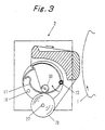
- this cleaning fabric take-up roll 70 diametrically enlarged to contact or interfere with the bottom member 17 of the container, its outer surface raises the bottom member 17, as shown in Fig. 3.
- the bottom member 17 starts its turning motion in the direction of arrow on the pin 13 so that its end portion leaves the receiving bar 18.
- the cavity space in the container is increased by the change in the remainder of the cleaning fabric supplying element 3.
- the bottom member 17 moves upward without any trouble, as shown.
- the change in the remainder of the cleaning fabric supplying element is exemplified by the reduction in the roll diameter in the case of the cleaning fabric roll 30 or by the reduction in the height in the case of the cleaning fabric in the folded pleated form.
- the cleaning fabric roll in the container, it is possible to reduce the diameter of the roll core extremely or to use the cleaning fabric supplying element having no roll core. Moreover, the size of the cleaning fabric unit can also be reduced by arranging the cleaning fabric take-up shaft close to the container.
- Fig. 4 a structure in which the bottom member is made of a deformable soft material.
- the construction other than the bottom member is identical to that of the embodiment shown in Fig. 1, and its description will be omitted by designating it by the common reference numerals.
- a deformable bottom member 29 is held at its two ends with a suitable slackness on a mounting bars 31 which are fixed on the side plate 9.
- the bottom member 29 is made of a material such as a fabric, a synthetic resin sheet or soft net.
- Fig. 6 shows a structure in which the cleaning fabric supplying element is placed on an immovable bottom member.
- the present embodiment is applied to the structure in which the container is placed on the supporting bar 10, but the present invention should not be limited thereto but can be modified into a structure in which the container itself shown in Fig. 1 is held by the side plate 9.
- the container is placed on the supporting bar 10, and a movable member 40, as hinged on a pin 41, is arranged above the container.
- the movable member 40 is urged outward, as indicated by arrow, by a spring 42.
- a free end 44 of the movable member is positioned inside of the end portion 45 of a stationary bottom member 43.
- the cleaning fabric take-up shaft 27 is arranged within a range in which it is so positioned above the movable member 40 as to face and interfere with the movable member 40 as the diameter of the cleaning fabric take-up roll 70 increases.
- the couplings between the cover 12 and the bottom member 17 and between the movable member 40 and the stationary container forming member 43 are effected through the pins.
- a synthetic resin material may be used to form a hinge of a thinned portion.
- cleaning fabric pull-back means for pull-back for reuse a portion of the used cleaning fabric, which has been supplied by the cleaning fabric advancing means, to the cleaning fabric supplying element.
- the basic construction of the container itself is similar to those of the foregoing individual embodiments.
- the present embodiment can be applied to any structure for mounting the cleaning fabric supplying element, such as the structure in which the same is mounted on the movable bottom member, as shown in Fig. 1, the structure in which the same is mounted on the deformable member, as shown in Fig. 4, or the structure in which the same is mounted on the stationary container constructing member, as shown in Fig. 6.
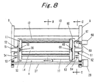
- Fig. 8 is a back elevation showing the cleaning unit with the cleaning fabric being removed.
- the container supporting receiver A is attached to the side plate (A)9.
- the container supporting receiver A is provided with a holding member (A)50 for holding one end of the container, and a spindle (A)51 disposed in the holding member (A)50.
- a spring (A)(52) for turning the holding member (A)50 in the direction (i.e., the counter-pull-out direction) opposite to the pull-out direction of the cleaning fabric.
- the spring (A)(52) is exemplified by a helical spring, as wound on the spindle (A)(51), as shown.
- first stop means for stopping the container which is turned by the pull-back rotational force stored in the spring 52, in a predetermined position.
- This first stop means is constructed by forming a projection 53 on the holding member (A)50 and a protrusion 54 at the side frame (A)9 so that it may stop the turn of the container as the projection 53 abuts against the protrusion 54.
- the holding member 50 is provided with a fitted portion 56 to be fitted in a square recess 55 formed in the end plate 11 of the container. As the fitted portion 56 is fitted in the recess 55, as shown, the holding member 50 can turn integrally with the container.
- This container supporting receiver 4 is provided with a holding member (B)60 for holding the other end of the container, and a spindle (B)61 disposed in the holding member (B)60.
- a spring (B)62 for applying a turning force to turn the holding member (B)60 in the direction (i.e., the counter-pull-out direction) opposite to the pull-out direction of the cleaning fabric.
- second stop means for stopping the container, which is turned by the pull-back rotational force stored in the spring 62, in a predetermined position.
- This second stop means is constructed by forming a projection 63 on the holding member (B)60 and a protrusion 64 at the side plate (B)9 so that it may stop the turn of the container as the projection 63 abuts against the protrusion 64.
- the position of the projection or protrusion can be made variable to adjust the pull-back motion of the container by changing that position. Thanks to this construction, the pull-back of the used cleaning fabric can be adjusted for reuse in accordance with the degree of blot of the cleaning fabric at each cleaning operation.
- the holding member 60 is provided with a fitted portion 66 to be fitted in a square recess 65 formed in the end plate 11 of the container. As the fitted portion 66 is fitted in the recess 65, as shown, the holding member 60 can turn integrally with the container.
- a retaining hole 67 is formed in such a face of the holding member 60 as to confront the side plate (B)9. The container is stopped in the position, as turned at the time of pull-out the cleaning fabric, by protruding and retaining a notch 69 in the retaining hole 67 by the retaining action of notch drive means 68.
- the cleaning fabric pull-out blocking means is disposed at each of the individual end portions of the cover 12 and the stationary plate 14, as forming the exit 15.
- a recess 73 is formed to extend in the longitudinal direction of the container.
- needle portions 74 which are so arranged at a predetermined interval in the longitudinal direction of the container as to pierce in the cleaning fabric 3a.
- the cover 12 is moved in the direction of arrow against the urging force of the spring 16 by the friction which is established by the S wrap formed between the two end portions 71 and 72, so that the needle portions 74 leave the cleaning fabric 3a being drawn out.
- the container turns in the direction of arrow of Fig. 9.
- the cover 12 is moved in the direction of arrow, as shown at (2) in Fig. 10, by the spring 16.
- the needle portions 74 pierce the cleaning fabric, as located between the two end portions, at the position of the recess 73 of the end portion 71 so that the cleaning fabric is bitten by the exit 15. If the container is turned in the arrow direction in this state, the used cleaning fabric is drawn back.
- the projection 63 is held in the position to abut against the protrusion 64 (in the state shown in Fig. 11) by the force applied in advance to the spring 62, namely, by the force to turn the container in the direction opposite to the cleaning fabric pull-out direction.
- the cleaning fabric take-up motor 28 is energized to take up the cleaning fabric 3a on the cleaning fabric take-up shaft 27.
- the container is turned in the direction (as indicated by the arrow in Fig. 12) to draw out the cleaning fabric by the friction at the instant when the cleaning fabric 3a passes through the S wrap of the container.
- the notch drive means 68 is actuated to protrude the notch 69.
- the retaining hole 67 is brought to the position of the notch 69 by the turning motion of the container, the notch 69 comes into the retaining hole 67.
- the container is held in the (A) position.
- the springs 52 and 62 store the pull-back force.
- the retention of the notch drive means 68 is released at the timing of ending the cleaning operation, the retention between the notch 69 and the retaining hole 67 is released so that the holding member 60 turns in the counter-pull-out direction together with the container, as shown in Fig. 13.
- the cleaning fabric pull-out blocking means acts to block the pull-out of the cleaning fabric from the cleaning fabric supplying element in the container. Simultaneously with this, a portion of the used cleaning fabric, e.g., about one half length of the used cleaning fabric is drawn back. At the next time of the cleaning operation, the used cleaning fabric having been drawn back is used at first so that the consumption of the cleaning fabric is reduced to utilize the resources effectively.
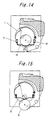
- Fig. 14 shows another embodiment of the movable bottom member.
- a bottom member 80 for mounting the cleaning fabric supplying element 3 is vertically movably supported by two guide portions 81 and 82. These guide portions 81 and 82 are mounted between the two end plates 11.
- the bottom member 80 is placed in the lowermost position of the guide portions 81 and 82 till the outer circumference of the cleaning fabric take-up roll 70 comes into abutment. When this abutment occurs, the cleaning fabric take-up roll 70 raises the bottom member 80, as shown in Fig. 15, as its diameter increases.
- Fig. 16 shows a construction of detecting the cleaning fabric end by using an optical sensor.
- This optical sensor 90 is arranged either inside of the stationary plate 14 or on the end plate 11.
- the optical sensor 90 optically detects a cleaning fabric end detecting mark on the cleaning fabric 3a, as is emanated from a hole formed in the stationary plate 14 through the exit 15.
- the detection signal is extracted from the end plate through the spindle 20 to the outside, as shown in Fig. 17, and is sent to the control unit of the not-shown cylinder cleaning device so that it is processed to monitor the end of the cleaning fabric.
- a limit switch 91 for detecting the cleaning fabric end is arranged downstream of the exit 15. This limit switch 91 is arranged either on the end plate 11 or outside of the stationary plate 14. In order to monitor the end of the cleaning fabric 3a, there is formed a hole in the vicinity of the widthwise edge of the cleaning fabric. There is processed the switch signal which is produced when the sensing lever of the limit switch 91 responds to that hole.
- the present invention may be embodied by a structure in which the same is introduced from the side end of the container.
- the cleaning fabric supplying element preferably the cleaning fabric roll is introduced into a container body 100 from its side end opening.
- the means for closing this opening is constructed of a cover member 101 having an annular portion for covering the opening from the outside, as shown at (1) in Fig. 19, or a cover member 102 having an insert to be inserted into the opening, as shown at (2) in Fig. 19.
- the outer surface of the cleaning fabric take-up roll need not act directly upon the bottom member, the movable member or the deformable member but can act upon the bottom member, the movable member or the deformable member indirectly through a mechanical association mechanism.
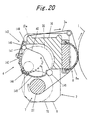
- Fig. 20 is a sectional view showing another embodiment.
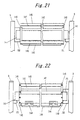
- Fig. 21 is a back elevation showing a construction of the cleaning unit with the crossbeam members being removed.
- Fig. 22 is a front elevation showing the construction of the cleaning unit with the crossbeam members being removed.
- the cleaning fabric supporting receiver 4 is equipped with semi-arcuate end members 140 which are arranged at the two sides. These end members 140 are equipped with journals 141 for supporting them on the side plates 9.
- a supporting plate 142 is fixed on the end members 140 which are positioned on the back side of the cleaning unit 2.
- a later-described cleaning fabric guide portion 143 is arranged at one end side of the supporting plate 142.
- a movable member 145 which is turnably supported by hinges 144.
- the movable member 145 of this embodiment constructs a cleaning fabric supporting receiver for receiving the outer surface of the cleaning fabric roll 30.
- a stay 146 which is mounted on the end members 140. This stay 146 receives the other end of the movable member 145 to regulate its rotation toward the cleaning fabric advancing means 7.
- the cleaning fabric take-up shaft 27 of the cleaning fabric advancing means 7 is arranged near the movable member 145. Specifically, the cleaning fabric 3a is taken up by the take-up shaft 27 of the cleaning fabric advancing means 7 so that the diameter of the cleaning fabric take-up roll 70 is increased. As a result, the outer surface of the cleaning fabric take-up roll 70 comes into interference with the movable member 145 to move the same in the direction, as indicated by broken lines. In other words, the cleaning fabric take-up roll 70 is diametrically enlarged whereas the cleaning fabric roll 30 at the side of the cleaning fabric supporting receiver is diametrically educed.
- Another method of moving the movable member may be exemplified by an indirect one in which the change in the diameter of the cleaning fabric take-up roll is detected to operate the actuating mechanism of the movable member on the basis of the detected result.
- the cleaning fabric guide portion 143 is equipped with a pair of round guide members 147 and 148. Between these guide members, there is formed an S-shaped passage for the cleaning fabric 3a to pass there through.
- the guide member 147 is arranged at the side of the cleaning fabric roll 30 whereas the guide member 148 is arranged at the side of the supporting bar 10.
- the guide member 147 is fixed at its two ends by the end members 140, and the other guide member 148 is supported at its two ends by supporting members 149 attached to the supporting plate 142.
- the supporting members 149 are made of an elastic material. The guide member, as supported by the supporting members, urges the cleaning fabric 3a passing through the S-shaped passage, in the direction to increase the friction with the other guide member.
- the supporting bar 10 has the extension 10a extending to the vicinity of the cleaning fabric guide portion 143.
- the cleaning fabric 3a is made to abut against the leading end of the extension 10a, and the guide member 148 is arranged in a position to push the cleaning fabric 3a onto the leading ends of the guide member 147 and the extension 10a of the supporting bar.
- the guide members should not be limited to the structure in which they are assembled as a portion of the cleaning fabric supporting receiver, but both or either of the guide members 147 and 148 may be mounted on the side plates 9. Likewise, the stay 146 may also be mounted on the cleaning fabric supporting receiver 4 or the side plates 9. Moreover, only one guide member 148 is urged, but the other guide member 147 may be urged in the direction opposite to that of the guide member 148 so that the cleaning fabric may be tensioned by the two guide members.
- a bearing portion 150 for receiving the journal 141 of the end member 140.
- a pair of pins 151 for mounting and positioning the journal 141 of the end member 140 at the opposite side.
- the cleaning fabric supporting receiver 4 When the cleaning fabric is to be set, the cleaning fabric supporting receiver 4 is removed from the cleaning unit 2, and the cleaning fabric roll 30 is placed on and supported by the movable member 145.
- the cleaning fabric 3a is drawn out through the S-shaped passage defined by the guide members 147 and 148, and the cleaning fabric supporting receiver 4 is then mounted on the cleaning unit 2.
- the journal of one end member 140 constructing the cleaning fabric supporting receiver 4 is inserted into the receiving portion 150 of the side plate 9, and the journal of the other end member 140 is supported on the paired pins 151 of the side plate 9. After this, the leading end of the cleaning fabric at the outside of the guide member is pulled and wrapped on the cleaning fabric take-up shaft 27 through the pressure pad 8a so that it is ready for use.
- the cleaning fabric take-up shaft 27 can be arranged in proximity of the cleaning fabric supporting receiver 4 thereby to reduce the size of the cleaning unit 2.
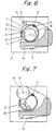
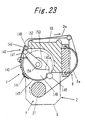
- the construction of the cleaning unit according to another embodiment is shown in Fig. 23.
- the present embodiment is characterized in the cleaning fabric guide portion in which one guide member is mounted on a turnable arm to allow the cleaning fabric to easily pass between the guide members.
- the end member 140 is equipped on its inner side with an arm mounting portion 153 which has a step 140a matching the turning range of an arm 152. From the arm mounting portion 153, there is projected an arm pin 154 for mounting the arm 152 turnably thereon.
- the guide member 147 is fixed on the leading end of the arm 152.
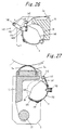
- FIG. 25 A modification of the present embodiment is shown in Fig. 25.
- the guide member 148 as arranged at the side of the supporting bar, is mounted on the arm 152.
- This arm 152 is turnably hinged to a bracket 140A which is fixed on the end member 140.
- the arm 152 is so urged by the not-shown torsion spring into the position, as indicated by the solid lines, as to form the S-shaped passage between the guide member 147 and the guide member 148.
- the cleaning fabric supporting receiver 4 When the cleaning fabric roll is to be charged, the cleaning fabric supporting receiver 4 is removed from the cleaning unit 2. After this, as shown in Fig. 24 or 26, the arm 152 is turned in a direction b, and the cleaning fabric roll 30 is placed on and received by the movable member 145. The leading portion of the cleaning fabric 3a is drawn out upward from the stationary guide member, and the arm 152 is turned in a direction a to thread the cleaning fabric into the clearance between the guide members 147 and 148. In this state, the cleaning fabric supporting receiver 4 is mounted in the cleaning unit 2 by a procedure similar to the embodiment shown in Fig. 20.
- the cleaning fabric 3a can be easily threaded through the cleaning fabric guide portion 143 so that the cleaning fabric roll 30 can be easily charged to improve the workability.
- FIG. 27 An embodiment shown in Fig. 27 is directed to a structure in which the cleaning fabric supporting receiver is fixed on the cleaning unit.
- Fig. 28 is a front elevation showing a construction of the cleaning fabric supporting receiver with the cover member being opened.
- a bottom plate 160 acting as a supporting member is attached to the end member 140 having a journal to be supported on the side plate 9.
- To the bottom plate 160 there is connected through the hinges 144 a cover member 162 for opening/closing an entrance to charge the cleaning fabric supporting receiver with the cleaning fabric roll 30.
- the cover member 162 is fastened in the closed state, as shown in Fig. 27, by a screw 163.
- the screw 163 is loosened and removed, and the cover member 162 is turned, as shown in Fig. 29, to open the entrance 161. Then, the cleaning fabric roll 30 is introduced into the entrance 161. In this operation, the leading portion of the cleaning fabric 3a is let off and placed on the guide member 147. The cleaning fabric 3a is wrapped along the pressure pad 8a on the cleaning fabric take-up shaft 27. After this, the cover member 162 is closed and fastened by the screw 163.
- the guide member 128 comes into the position, as shown in Fig. 27, to form the S-shaped passage for allowing the cleaning fabric 3a to pass there through. Simultaneously with this, the cleaning fabric 3a is tensioned by the action of the elastic force of the supporting member 149.
- the cleaning fabric roll can be charged without removing the cleaning fabric supporting receiver from the cleaning unit so that the cleaning fabric roll can be efficiently exchanged.
- An embodiment, as shown in Fig. 30, is directed to a structure in which the movable member side of the cleaning fabric supporting receiver can be widely opened at the time of charging the cleaning fabric roll.
- the cleaning fabric supporting receiver 4 is equipped with the movable member 145 and a cover member 162A.
- One side of this cover member 162A is connected to the movable member 145 by the hinge 144.
- the other side of the cover member 162A is connected to the support plate 142 through a hinge 144A.
- the cover member 162A is fixed on the end member 140 by the screw 163.
- the stay 146 With the cover member 162A being fixed, the stay 146 is arranged in the downward turning locus of the movable member 145 on the hinge 144 so that the other side of the movable member is in abutment against the stay, as shown in Fig. 30, to regulate the downward turn.
- the movable member 145 As the cleaning fabric take-up roll is diametrically enlarged, the movable member 145 is turned by the hinge of the cover member 162A which is fixed as in the embodiment of Fig. 20 by the outer circumference of the enlarged diameter of the cleaning fabric take-up roll.
- the cleaning fabric take-up roll is removed at first from the cleaning fabric take-up shaft 27, and the screw 163 is then loosened.
- the movable member 145 is turned on the hinge 144, and the cover member 162A is turned on the hinge 144A.
- the cleaning fabric roll 30 is introduced into the opening.
- the movable member 145 is introduced into the cleaning fabric supporting receiver 4 while guiding its other side at this side of the stay 146, and the cover member 162A is fixed on the end member 140 by the screw 163.
- the cleaning fabric roll 30 is charged, and the cleaning fabric guide portion 143 is threaded into the cleaning fabric guide portion 143 thereby to set the cleaning fabric roll 30 by turning the arm 152 in the arrow direction.
- the cleaning fabric supporting receiver is turnably mounted on the side plate so that it can be widely opened at the time of charging the cleaning fabric roll.
- the cleaning fabric supporting receiver 4 is so mounted as to turn on a stay 146A attached to the side plate 9.
- a stationary portion 180 is provided for holding the shown position.
- the cleaning fabric supporting receiver 4 can be turned over the arranged region of the cleaning fabric take-up shaft 27, as shown in Fig. 35, by removing the cleaning fabric take-up shaft 27.
- Reference numeral 153 designates a bearing portion which is formed in the side plate 9 and to which is connected the cleaning fabric take-up shaft 27.
- the stationary portion 180 is constructed of a click mechanism 183, as shown in Fig. 34.
- the cleaning fabric supporting receiver 4 is fixed by inserting a fixing pin 181, as projected from the side plate 9, into a hole 140b formed in the end member 140.
- a knob 182 for operating the fixing pin 181.
- In one of the annular grooves there is fitted a ball which is urged by a spring.
- the click mechanism 183 is composed of the annular grooves formed in the fixing pin 181, the ball to engage with the annular grooves, and the spring for urging the ball toward the annular grooves.
- the cleaning fabric take-up shaft is removed together with the cleaning fabric take-up roll, and the fixing portion is operated to release the cleaning fabric supporting receiver.
- the cleaning fabric supporting receiver is turned on the stay, as shown in Fig. 35, so that it is widely opened at the side of the cleaning fabric guide portion 143.
- the cleaning fabric roll is inserted into the cleaning fabric supporting receiver.
- the leading portion of the cleaning fabric is threaded through the cleaning fabric guide portion, and the cleaning fabric supporting receiver is then turned toward the supporting bar.
- the fixing portion is operated to fix the cleaning fabric supporting receiver at the position, as shown in Fig. 33.
- the cleaning fabric roll can be easily inserted by turning the cleaning fabric supporting receiver as a whole toward the cleaning fabric take-up shaft to open the cleaning fabric guide portion widely, and the cleaning unit can be small-sized by arranging the cleaning fabric take-up shaft in the proximity of the movable member.
- the cleaning fabric guide portion is constructed one guide member and a portion of the supporting bar.
- the guide member 148 is supported at its two ends on the support member 149 which is attached to the support plate 142.
- the cleaning fabric 3a advances between the guide member 148 and the end face of the extension 10a of the supporting bar.
- the supporting member 149 is made of an elastic material to push the cleaning fabric 3a onto the supporting bar 10.
- a cleaning fabric guide portion 170 for the downstream side.
- This cleaning fabric guide portion 170 is formed at the leading end of a guide plate 171 which is fixed on the supporting bar 10 or the supporting plate 9.
- the cleaning fabric 3a as located between the cleaning fabric supporting receiver 4 and the downstream cleaning fabric guide portion 170, is tensioned by pushing it onto the extension of the supporting bar by the guide member 148 of the cleaning fabric guide portion 143 thereby to establish a high friction between the guide portions.
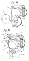
- FIG. 38 An embodiment of Fig. 38 is directed to a structure in which a disengagement preventing mechanism for preventing the cleaning fabric roll or the roll core from disengaging out is added to the cleaning unit.
- a disengagement preventing mechanism for preventing the cleaning fabric roll or the roll core from disengaging out is added to the cleaning unit.
- the guide member 148 composing the cleaning fabric guide portion 143 is given a length larger than the width of the cleaning fabric roll.
- a disengagement preventing member 172 (e.g., 172A and 172B) is disposed between the cleaning fabric guide portion 143 and the downstream cleaning fabric guide portion 170 and in the vicinity of the downstream cleaning fabric guide portion 170.
- the disengagement preventing members 172A and 172B are positioned outside of the two side portions of the cleaning fabric roll and arranged at a gap smaller than the length of the guide member 148.
- the cleaning fabric roll 30 When the cleaning fabric roll 30 is disengaged out from the cleaning fabric supporting receiver 4 by the intense pull of the cleaning fabric 3a, it comes at first into abutment against the guide member 148, as shown in Fig. 40, so that the guide member 148 moves in the direction of arrow while deforming the supporting member 149. This motion is stopped when the two ends of the guide member 148 come into abutment against the disengagement preventing members 172A and 172B. While the two ends of the guide member 148 are thus abutting against the disengagement preventing members 172A and 172B, the clearance between the guide member 148 and the lower face of the guide plate 171 of the downstream cleaning fabric guide portion 170 is narrowed to block the passage of the cleaning fabric roll 30 or a roll core 3b.
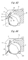
- FIG. 41 A modification of the disengagement preventing mechanism is shown in Fig. 41.
- the cleaning fabric supply element in which the roll core 3b of the cleaning fabric roll 30 is made longer than the roll width and projected from the two sides.
- the disengagement preventing mechanism is disposed close to and downstream of the guide members which form the S-shaped passage for allowing the cleaning fabric to pass there through.
- the disengagement preventing members 172A and 172B are arranged on the disengagement orbit of the roll core 3b which is protruded from the two sides of the cleaning fabric roll.
- the roll core 3b and the diametrically reduced cleaning fabric roll 30 are hooked and stopped at the two ends of the roll core 3b, when they pass and disengagement off the cleaning fabric guide portion, by the disengagement preventing members 172A and 172B, as shown in Fig. 42.
- the roll core 3b has insufficient bending strength, its central portion is deformed or bulged by the tension of the cleaning fabric.
- the roll core, as hooked by the dis-engagement preventing members may come out to disengagement out of the cleaning unit.
- the method of giving the guide members the disengagement preventing mechanism is executed by intensifying the urging force to the guide members such as by making the supporting member itself of a strong elastic material or by strengthening the spring of the arm carrying the guide members.
- the present embodiment has been described to have the construction of one guide member 148. Despite of this description, however, the present invention can naturally be applied to the construction having the two guide members 147 and 148, as represented by the cleaning fabric guide portion shown in Fig. 20.
- a cleaning fabric tensioning mechanism for preventing the cleaning fabric from becoming slack.
- the cleaning fabric tensioning mechanism may be constructed either by using one or both of the guide members as a portion of the cleaning fabric supporting receiver or by the entirety of the cleaning fabric supporting receiver.
- a cleaning fabric tensioning mechanism 190 of Fig. 43 is constructed by using one guide member.
- One end 149a of the supporting member is turnably attached to the side of the cleaning fabric supporting receiver or the side plate.
- the supporting member 149 is urged in the direction of arrow by a spring 191.
- the cleaning fabric 3a is pushed and tensioned between the guide member 147 and the supporting bar 10 through the guide member 148 by the action of the spring 191.
- a cleaning fabric tensioning mechanism as shown in Fig. 44, the cleaning fabric supporting receiver 4 is turnably mounted on the stay 146A. Between the cleaning fabric supporting receiver 4 and the side plate 9, there is arranged a spring 192 for urging the cleaning fabric supporting receiver 4 in the direction of arrow. The cleaning fabric 3a is pulled and tensioned in the direction of arrow through the cleaning fabric guide portion 143.
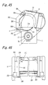
- Fig. 45 to 50 Further embodiment of the present invention is shown in Fig. 45 to 50.
- Fig. 45 is section view showing further embodiment and Fig. 46 is a front elevation showing a cleaning unit.
- a cleaning fabric passage is formed for applying brake force to the cleaning fabric by utilizing the end portion of an inner surface of the supporting bar 10 extending between the side frames 9.
- the cleaning fabric supporting receiver 4 includes a movably member 201 and a supporting plate 203 secured to arm member 202.
- the side frame are provided with shaft mounting blocks 200 on which shafts 200A are mounted.
- the movable member 201 and arm members 202 are rotatably supported on the shafts 202A.
- the movable member 201 is located in substantially horizontal position and the supporting plate 203 is located in substantially vertical position.
- the cleaning fabric roll 30 is accommodated in a space defined by the movable member 201, the supporting plate 203 and the supporting bar 10 and is placed on the movable member 201.
- the movable member 201 extends longitudinally of the cleaning fabric roll 30 and has a recess inclined toward the central portion thereof.
- End plates 204 are provided on two sides of the movable member 201 opposite to the side frames 9 to cover the lower portions of the cleaning fabric roll 30. End plates 204 limit the movement of the cleaning fabric roll 30 in longitudinal direction so that it can be held stably and reliably on the movable member 201.
- the movable member 201 is prevented from downward pivotal movement by stoppers 205 to be maintained in substantially horizontal position as shown.
- the supporting plate 203 is located in substantially vertical position opposite to the outer circumference of the cleaning fabric roll 30.
- the top end of the supporting plate 203 is positioned in the vicinity of the end portion of an inner surface of the supporting bar 10.
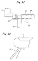
- a supporting plate securing mechanism is shown in which the end portions of the supporting plate 203 are secured to the side frames 9.
- This securing mechanism comprises a tubular member 206 mounted near the end portion of the supporting plate and extending over the whole length in a longitudinal direction of the supporting plate, securing member 207 projecting from both ends of the tubular member 206 toward the side frame 9 and engaging holes 208 formed in the side frames 9.
- Guide slots 210 are formed in the tubular member 206 for operating knobs 209 secured to the securing members 207 (shown in Fig. 47 with a broken line).
- Fig. 47 is a plan view of the securing mechanism provided to one of the side frames 9 and shows the securing mechanism in set condition.
- Fig. 49 shows a cleaning fabric supporting receiver in opened condition.
- the cleaning fabric roll 30 can be charged from the opening to put it on the movable member 201.
- the top end of the supporting plate 203 is arranged to position inwards from the inner end of the supporting bar 10 (about 5 mm ) as shown in Fig. 48 to form a space 211 (about 1 mm ) between these portions, through which the cleaning fabric can passes.
- the top end of the supporting plate 203 and the supporting bar 10 define an S-shaped passage and an braking force is exerted on the cleaning fabric fed through the S-shaped passage.
- the cleaning fabric take-up shaft 27 of the cleaning fabric advancing means 7 is disposed in the vicinity of the movable member 201.
- the cleaning fabric 3a is wound up by the take-up shaft 27 of the cleaning fabric advancing means 7 so that the diameter of the cleaning fabric take-up roll 70 increased.
- the outer circumference of the cleaning fabric take-up roll 70 comes into interference with the movable member 201 to move it in the direction by the arrow as shown in Fig. 50. Since this movement of the movable member 201 acts to push the diametrically reduced cleaning fabric roll 30 onto the inner face of the supporting plate 203, the cleaning fabric roll 30 is held stably and reliably in the cleaning fabric supporting receiver 4.
Landscapes
- Inking, Control Or Cleaning Of Printing Machines (AREA)
Claims (19)
- Zylinderreinigungsvorrichtung zum Reinigen einer Außenseite eines Zylinders (1) durch Pressen eines Reinigungstuchs (3a), das von einem Reinigungstuchzufuhrelement (3) zugeführt wird, gegen die Außenseite des Zylinders, aufweisend:dadurch gekennzeichnet, dass die Zylinderreinigungsvorrichtung einen Reinigungstuchzufuhrelementbehälter (4) aufweist, der auf dem Rahmen getragen ist; wobei die Reinigungstuchaufnahmewelle (27) in einem Bereich angeordnet ist, in welchem sie mit dem Behälter (4) in Eingriff gelangt, wenn der Durchmesser der Reinigungstuchaufnahmewelle (7) zunimmt, undeinen Rahmen; undeine Reinigungstuchaufnahmewelle (27), die an dem Rahmen angebracht ist, um unter Bilden einer Reinigungstuchaufnahmerolle gebrauchtes Reinigungstuch aufzunehmen,
wobei der Behälter (4) eine Struktur aufweist, deren Form in einer Richtung zunehmenden Durchmessers der Reinigungstuchaufnahmerolle (7) sich körperlich ändert. - Zylinderreinigungsvorrichtung nach Anspruch 1, wobei ein bewegliches Element (17) in einem Abschnitt des Behälters (4) in Gegenüberlage zu der Reinigungstuchaufnahmewelle (27) angeordnet und relativ in Übereinstimmung mit der Zunahme des Durchmessers der Reinigungstuchaufnahmerolle (70) bewegt ist.
- Zylinderreinigungsvorrichtung nach Anspruch 2, wobei die Außenseite der Reinigungstuchaufnahmerolle (70) dazu ausgelegt ist, direkt auf das bewegliche Element (17) des Behälters (4) einzuwirken, wenn die Reinigungstuchaufnahmerolle (70) bezüglich des Durchmessers zunimmt, um dadurch das bewegliche Element (17) zu bewegen.
- Zylinderreinigungsvorrichtung nach Anspruch 2, wobei die Reinigungstuchaufnahmerolle (70) dazu ausgelegt ist, indirekt auf das bewegliche Element (17) des Behälters (4) einzuwirken, wenn der Durchmesser der Reinigungstuchaufnahmerolle zunimmt, um dadurch das bewegliche Element zu bewegen.
- Zylinderreinigungsvorrichtung nach Anspruch 1, wobei ein verformbares Element (29) in einem Abschnitt des Behälters (4) in Gegenüberlage zu der Reinigungstuchaufnahmewelle (27) angeordnet ist und dadurch verformt wird, dass der Außenumfang der Reinigungstuchaufnahmerolle (70) veranlasst wird, auf das verformbare Element des Behälters in Übereinstimmung mit der Zunahme des Durchmessers der Reinigungstuchaufnahmerolle (70) einzuwirken.
- Zylinderreinigungsvorrichtung nach einem der Ansprüche 1 bis 3, wobei der Behälter ein Bodenelement (17) zur Aufnahme des Reinigungstuchzufuhrelements aufweist, und
wobei das Bodenelement (17) zu der Reinigungstuchaufnahmewelle (27) weist und ein bewegliches Element bildet, das durch Eingriff mit der Reinigungstuchaufnahmerolle (70) bewegt wird, die auf der Reinigungstuchaufnahmewelle (27) aufgenommen ist. - Zylinderreinigungsvorrichtung nach einem der Ansprüche 1 bis 5, wobei der Behälter ein Bodenelement (29) zur Aufnahme des Reinigungstuchzufuhrelements (3) umfasst, und wobei das Bodenelement (29) zu der Reinigungstuchaufnahmewelle weist und ein verformbares Element bildet, das durch den Eingriff mit der Reinigungstuchaufnahmerolle (70) verformt wird, die auf der Reinigungstuchaufnahmewelle (27) aufgenommen ist.
- Zylinderreinigungsvorrichtung nach einem der Ansprüche 1 bis 7, wobei der Behälter (4) eine Bremseinrichtung (10a; 44, 45) zum Anwenden einer Bremse auf das Reinigungstuch (3a) umfasst.
- Zylinderreinigungsvorrichtung nach einem der Ansprüche 1 bis 8, wobei der Behälter (4) eine Reinigungstuchspanneinrichtung (147, 148) zum Spannen des Reinigungstuchs umfasst.
- Zylinderreinigungsvorrichtung nach einem der Ansprüche 1 bis 9, wobei der Behälter (4) drehbar getragen ist und außerdem aufweist:eine Reinigungstuchrückzieheinrichtung (52) zum Rückziehen eines Abschnitts des benutzten Reinigungstuchs (3a) durch Drehen des Behälters (4) in einer Richtung entgegengesetzt zu derjenigen zum Herausziehen des Reinigungstuchs (3a); undeine Reinigungstuchausziehsperreinrichtung (73, 74) zum Sperren des Herausziehens des Reinigungstuchs aus dem Behälter, wenn die Reinigungstuchrückzieheinrichtung (52) aktiv ist.
- Zylinderreinigungsvorrichtung nach einem der Ansprüche 1 bis 10, wobei der Behälter eine Einrichtung (90) zum Ermitteln des Endes des Reinigungstuchs (3a) umfasst.
- Zylinderreinigungsvorrichtung nach Anspruch 1, wobei der Behälter (4) eine in seiner Längsaußenseite gebildete Öffnung zum Einführen des Reinigungstuchzufuhrelements (3) in diesen aufweist.
- Zylinderreinigungsvorrichtung nach einem der Ansprüche 1 bis 12, wobei der Behälter (100) eine Öffnung aufweist, die in zumindest einer seiner Seitenenden gebildet ist, um das Reinigungstuchzufuhrelement in ihn einzuleiten.
- Zylinderreinigungsvorrichtung nach einem der Ansprüche 1 bis 13, wobei der Behälter (4) einen Ausgang (15) zum Herausziehen des Reinigungstuchs aufweist, und
wobei an dem Ausgang (15) eine der folgenden Einrichtungen angeordnet ist:eine Bremseinrichtung (44, 45) zum Anwenden einer Bremse auf das Reinigungstuch, wenn es herausgezogen wird;eine Reinigungstuchrückzieheinrichtung (42) zum Zurückziehen eines Abschnitts des gebrauchten Reinigungstuchs durch Drehen des Behälters in einer Richtung entgegengesetzt zu derjenigen zum Herausziehen des Reinigungstuchs; undeine Reinigungstuchherausziehsperreinrichtung (73, 74) zum Sperren des Herausziehens des Reinigungstuchs aus dem Behälter, wenn die Reinigungstuchherauszieheinrichtung (52) aktiv ist. - Zylinderreinigungsvorrichtung nach Anspruch 12, wobei der Behälter (4) ein bewegliches Abdeckelement (12) zum Verschließen der Öffnung aufweist, und wobei ein Ausgang (15) zwischen einem freien Endrand des Abdeckelements (12) und einem benachbarten Rand der Öffnung gebildet ist.
- Zylinderreinigungsvorrichtung nach Anspruch 15, wobei die Bremseinrichtung mit Führungseinrichtungen versehen ist, die an dem freien Endrand der Abdeckung (12) und dem benachbarten Rand der Öffnung angeordnet ist und einen S-förmigen Durchtritt zwischen diesen festlegt, um das Reinigungstuch dort hindurch treten zu lassen.
- Zylinderreinigungsvorrichtung nach Anspruch 16, wobei die Führungseinrichtung (71, 72) eine Sperreinrichtung (73, 74) zum Sperren des Herausziehens des Reinigungstuchs (3a) während der Rückziehwirkung des Reinigungstuchs durch Drehen des Behälters (4) in einer Richtung entgegengesetzt zur Richtung zum Herausziehen des Reinigungstuchs umfasst, wobei die Sperreinrichtung an dem Reinigungstuch angreift, wenn die Führungseinrichtungen im gegenseitigen Kontakt durch Spannen des Reinigungstuchs gebracht sind.
- Zylinderreinigungsvorrichtung nach Anspruch 11, wobei die Reinigungstuchaufhahmewelle (27) sich in Gegenüberlage zu einem oberen Bereich des Behälters (4) befindet und wobei in dem oberen Bereich des Behälters ein bewegliches Abdeckelement (4) vorgesehen ist, das durch Eingriff mit der größer werdenden Reinigungstuchaufnahmerolle (70) in einer Richtung zur Innenseite des Behälters (4) bewegt wird.
- Zylinderreinigungsvorrichtung nach Anspruch 18, wobei an dem freien Endrand des beweglichen Abdeckelements (40) und einem benachbarten Rand einer durch die Abdeckelementführungseinrichtung (44, 45) abgedeckten Öffnung ein S-förmiger Durchlass dazwischen gebildet ist, um das Reinigungstuch (3a) dort hindurchtreten zu lassen.
Priority Applications (1)
| Application Number | Priority Date | Filing Date | Title |
|---|---|---|---|
| EP01124887A EP1174264A1 (de) | 1996-04-09 | 1997-04-08 | Zylinderreinigungsvorrichtung und Vorrichtung zur Ablage des Reinigungstuches |
Applications Claiming Priority (6)
| Application Number | Priority Date | Filing Date | Title |
|---|---|---|---|
| JP11201696 | 1996-04-09 | ||
| JP112016/96 | 1996-04-09 | ||
| JP11201696A JP2904479B2 (ja) | 1996-04-09 | 1996-04-09 | シリンダ洗浄装置 |
| JP26246596 | 1996-09-11 | ||
| JP26246596 | 1996-09-11 | ||
| JP262465/96 | 1996-09-11 |
Related Child Applications (1)
| Application Number | Title | Priority Date | Filing Date |
|---|---|---|---|
| EP01124887A Division EP1174264A1 (de) | 1996-04-09 | 1997-04-08 | Zylinderreinigungsvorrichtung und Vorrichtung zur Ablage des Reinigungstuches |
Publications (3)
| Publication Number | Publication Date |
|---|---|
| EP0800918A2 EP0800918A2 (de) | 1997-10-15 |
| EP0800918A3 EP0800918A3 (de) | 1998-02-11 |
| EP0800918B1 true EP0800918B1 (de) | 2002-07-24 |
Family
ID=26451279
Family Applications (2)
| Application Number | Title | Priority Date | Filing Date |
|---|---|---|---|
| EP19970105784 Expired - Lifetime EP0800918B1 (de) | 1996-04-09 | 1997-04-08 | Zylinderreinigungsvorrichtung und Vorrichtung zur Ablage des Reinigungstuches |
| EP01124887A Withdrawn EP1174264A1 (de) | 1996-04-09 | 1997-04-08 | Zylinderreinigungsvorrichtung und Vorrichtung zur Ablage des Reinigungstuches |
Family Applications After (1)
| Application Number | Title | Priority Date | Filing Date |
|---|---|---|---|
| EP01124887A Withdrawn EP1174264A1 (de) | 1996-04-09 | 1997-04-08 | Zylinderreinigungsvorrichtung und Vorrichtung zur Ablage des Reinigungstuches |
Country Status (4)
| Country | Link |
|---|---|
| EP (2) | EP0800918B1 (de) |
| KR (1) | KR970069336A (de) |
| CN (1) | CN1172010A (de) |
| DE (1) | DE69714119T2 (de) |
Families Citing this family (1)
| Publication number | Priority date | Publication date | Assignee | Title |
|---|---|---|---|---|
| CN101326059A (zh) * | 2005-12-09 | 2008-12-17 | 菲内勒特拉国际股份有限公司 | 用于印刷机滚筒清洁组件的驱动系统 |
Family Cites Families (6)
| Publication number | Priority date | Publication date | Assignee | Title |
|---|---|---|---|---|
| DE1224752B (de) * | 1965-08-20 | 1966-09-15 | Agfa Gevaert Ag | Reinigungs- oder Vorfeuchteinrichtung fuer Buero-Offsetdruckmaschinen |
| JPH0276740A (ja) * | 1988-09-13 | 1990-03-16 | Nikka Kk | 印刷機のブランケット洗浄装置及び洗浄方法 |
| EP0364901B1 (de) * | 1988-10-19 | 1994-04-27 | Dai Nippon Insatsu Kabushiki Kaisha | Reinigungssystem für Bogenoffsetdruckmaschinen |
| US5176080A (en) * | 1990-09-20 | 1993-01-05 | Baldwin Technology Corporation | Cloth supply system for blanket cylinder for use in printing presses |
| JP3006820B2 (ja) * | 1994-06-08 | 2000-02-07 | 清水製作株式会社 | 印刷機のドラム洗浄装置 |
| JP3240311B2 (ja) * | 1995-12-29 | 2001-12-17 | 日本ボールドウィン株式会社 | シリンダ洗浄装置 |
-
1997
- 1997-04-08 DE DE1997614119 patent/DE69714119T2/de not_active Expired - Fee Related
- 1997-04-08 EP EP19970105784 patent/EP0800918B1/de not_active Expired - Lifetime
- 1997-04-08 KR KR1019970012868A patent/KR970069336A/ko not_active Ceased
- 1997-04-08 CN CN 97113458 patent/CN1172010A/zh active Pending
- 1997-04-08 EP EP01124887A patent/EP1174264A1/de not_active Withdrawn
Also Published As
| Publication number | Publication date |
|---|---|
| DE69714119D1 (de) | 2002-08-29 |
| EP0800918A3 (de) | 1998-02-11 |
| EP0800918A2 (de) | 1997-10-15 |
| EP1174264A1 (de) | 2002-01-23 |
| KR970069336A (ko) | 1997-11-07 |
| CN1172010A (zh) | 1998-02-04 |
| DE69714119T2 (de) | 2003-03-27 |
Similar Documents
| Publication | Publication Date | Title |
|---|---|---|
| JP3512418B2 (ja) | 支持ローラ型巻取り機 | |
| US6412725B2 (en) | Supply magazine for containing recording material roll | |
| KR100418690B1 (ko) | 타월디스펜서에평평한스트립재료를결합하는방법및상기방법을수행하는장치 | |
| JPH03183566A (ja) | ラベルプリンター装置 | |
| JP2658111B2 (ja) | 手動式プリンタ | |
| US4769652A (en) | Method and apparatus for handling sheet materials | |
| JPH02210464A (ja) | 画像形成装置 | |
| EP0800918B1 (de) | Zylinderreinigungsvorrichtung und Vorrichtung zur Ablage des Reinigungstuches | |
| US6634589B2 (en) | Ink film holding device and film reel | |
| US6038731A (en) | Cylinder cleaning device | |
| JPH03114769A (ja) | リボンカセット | |
| JPH0215395B2 (de) | ||
| JP2904479B2 (ja) | シリンダ洗浄装置 | |
| JPH0739177B2 (ja) | 印刷機のシリンダまたはローラ洗浄装置 | |
| JP2993560B2 (ja) | シリンダ洗浄装置および洗浄ファブリック支承装置 | |
| JP2000313551A (ja) | ロール紙巻取り装置を用いた印刷装置 | |
| JP2507581B2 (ja) | 巻き付き状態で可撓性ウエブを貯蔵する装置 | |
| JPS599358B2 (ja) | リボンカ−トリツジ | |
| JP2951437B2 (ja) | 写真プリンタ用ペーパーマガジン | |
| JP2644791B2 (ja) | 熱転写記録装置 | |
| JP2006123190A (ja) | ラベルプリンタ | |
| JP3945615B2 (ja) | ロール紙給紙装置 | |
| JPS5851011Y2 (ja) | 印字装置 | |
| JP2893815B2 (ja) | ウエブ検知装置 | |
| US4221349A (en) | Automatic film threading mechanism |
Legal Events
| Date | Code | Title | Description |
|---|---|---|---|
| PUAI | Public reference made under article 153(3) epc to a published international application that has entered the european phase |
Free format text: ORIGINAL CODE: 0009012 |
|
| AK | Designated contracting states |
Kind code of ref document: A2 Designated state(s): DE ES FR GB IT NL SE |
|
| PUAL | Search report despatched |
Free format text: ORIGINAL CODE: 0009013 |
|
| AK | Designated contracting states |
Kind code of ref document: A3 Designated state(s): DE ES FR GB IT NL SE |
|
| 17P | Request for examination filed |
Effective date: 19980720 |
|
| 17Q | First examination report despatched |
Effective date: 19990222 |
|
| GRAG | Despatch of communication of intention to grant |
Free format text: ORIGINAL CODE: EPIDOS AGRA |
|
| GRAG | Despatch of communication of intention to grant |
Free format text: ORIGINAL CODE: EPIDOS AGRA |
|
| GRAH | Despatch of communication of intention to grant a patent |
Free format text: ORIGINAL CODE: EPIDOS IGRA |
|
| GRAH | Despatch of communication of intention to grant a patent |
Free format text: ORIGINAL CODE: EPIDOS IGRA |
|
| GRAA | (expected) grant |
Free format text: ORIGINAL CODE: 0009210 |
|
| RAP1 | Party data changed (applicant data changed or rights of an application transferred) |
Owner name: BALDWIN-JAPAN LTD. |
|
| AK | Designated contracting states |
Kind code of ref document: B1 Designated state(s): DE ES FR GB IT NL SE |
|
| PG25 | Lapsed in a contracting state [announced via postgrant information from national office to epo] |
Ref country code: NL Free format text: LAPSE BECAUSE OF FAILURE TO SUBMIT A TRANSLATION OF THE DESCRIPTION OR TO PAY THE FEE WITHIN THE PRESCRIBED TIME-LIMIT Effective date: 20020724 |
|
| REG | Reference to a national code |
Ref country code: GB Ref legal event code: FG4D |
|
| REF | Corresponds to: |
Ref document number: 69714119 Country of ref document: DE Date of ref document: 20020829 |
|
| PG25 | Lapsed in a contracting state [announced via postgrant information from national office to epo] |
Ref country code: SE Free format text: LAPSE BECAUSE OF FAILURE TO SUBMIT A TRANSLATION OF THE DESCRIPTION OR TO PAY THE FEE WITHIN THE PRESCRIBED TIME-LIMIT Effective date: 20021024 |
|
| NLV1 | Nl: lapsed or annulled due to failure to fulfill the requirements of art. 29p and 29m of the patents act | ||
| PG25 | Lapsed in a contracting state [announced via postgrant information from national office to epo] |
Ref country code: ES Free format text: LAPSE BECAUSE OF FAILURE TO SUBMIT A TRANSLATION OF THE DESCRIPTION OR TO PAY THE FEE WITHIN THE PRESCRIBED TIME-LIMIT Effective date: 20030130 |
|
| ET | Fr: translation filed | ||
| PLBE | No opposition filed within time limit |
Free format text: ORIGINAL CODE: 0009261 |
|
| STAA | Information on the status of an ep patent application or granted ep patent |
Free format text: STATUS: NO OPPOSITION FILED WITHIN TIME LIMIT |
|
| 26N | No opposition filed |
Effective date: 20030425 |
|
| PGFP | Annual fee paid to national office [announced via postgrant information from national office to epo] |
Ref country code: GB Payment date: 20040407 Year of fee payment: 8 |
|
| PGFP | Annual fee paid to national office [announced via postgrant information from national office to epo] |
Ref country code: FR Payment date: 20040408 Year of fee payment: 8 |
|
| PGFP | Annual fee paid to national office [announced via postgrant information from national office to epo] |
Ref country code: DE Payment date: 20040415 Year of fee payment: 8 |
|
| PG25 | Lapsed in a contracting state [announced via postgrant information from national office to epo] |
Ref country code: IT Free format text: LAPSE BECAUSE OF NON-PAYMENT OF DUE FEES;WARNING: LAPSES OF ITALIAN PATENTS WITH EFFECTIVE DATE BEFORE 2007 MAY HAVE OCCURRED AT ANY TIME BEFORE 2007. THE CORRECT EFFECTIVE DATE MAY BE DIFFERENT FROM THE ONE RECORDED. Effective date: 20050408 Ref country code: GB Free format text: LAPSE BECAUSE OF NON-PAYMENT OF DUE FEES Effective date: 20050408 |
|
| PG25 | Lapsed in a contracting state [announced via postgrant information from national office to epo] |
Ref country code: DE Free format text: LAPSE BECAUSE OF NON-PAYMENT OF DUE FEES Effective date: 20051101 |
|
| GBPC | Gb: european patent ceased through non-payment of renewal fee |
Effective date: 20050408 |
|
| PG25 | Lapsed in a contracting state [announced via postgrant information from national office to epo] |
Ref country code: FR Free format text: LAPSE BECAUSE OF NON-PAYMENT OF DUE FEES Effective date: 20051230 |
|
| REG | Reference to a national code |
Ref country code: FR Ref legal event code: ST Effective date: 20051230 |