EP0800924A2 - Bilderzeugungsgerät mit verbesserter Bogenausgabevorrichtung - Google Patents
Bilderzeugungsgerät mit verbesserter Bogenausgabevorrichtung Download PDFInfo
- Publication number
- EP0800924A2 EP0800924A2 EP97106003A EP97106003A EP0800924A2 EP 0800924 A2 EP0800924 A2 EP 0800924A2 EP 97106003 A EP97106003 A EP 97106003A EP 97106003 A EP97106003 A EP 97106003A EP 0800924 A2 EP0800924 A2 EP 0800924A2
- Authority
- EP
- European Patent Office
- Prior art keywords
- sheet
- image forming
- forming apparatus
- support means
- support
- Prior art date
- Legal status (The legal status is an assumption and is not a legal conclusion. Google has not performed a legal analysis and makes no representation as to the accuracy of the status listed.)
- Granted
Links
- 238000007599 discharging Methods 0.000 claims abstract description 31
- 238000005452 bending Methods 0.000 claims description 15
- 230000002093 peripheral effect Effects 0.000 claims description 9
- 230000004044 response Effects 0.000 claims description 5
- 239000011435 rock Substances 0.000 claims description 4
- 238000009835 boiling Methods 0.000 claims description 2
- 239000000976 ink Substances 0.000 description 35
- 238000010276 construction Methods 0.000 description 10
- 239000007788 liquid Substances 0.000 description 9
- 238000000034 method Methods 0.000 description 7
- 238000011109 contamination Methods 0.000 description 6
- 238000007796 conventional method Methods 0.000 description 5
- 230000009471 action Effects 0.000 description 3
- 230000008901 benefit Effects 0.000 description 3
- 238000010438 heat treatment Methods 0.000 description 3
- 230000003247 decreasing effect Effects 0.000 description 2
- 239000000463 material Substances 0.000 description 2
- 230000007246 mechanism Effects 0.000 description 2
- 230000001360 synchronised effect Effects 0.000 description 2
- 230000008859 change Effects 0.000 description 1
- 230000008602 contraction Effects 0.000 description 1
- 238000001514 detection method Methods 0.000 description 1
- 238000001035 drying Methods 0.000 description 1
- 239000013013 elastic material Substances 0.000 description 1
- 238000004519 manufacturing process Methods 0.000 description 1
- 238000002360 preparation method Methods 0.000 description 1
- 230000001737 promoting effect Effects 0.000 description 1
- 238000005096 rolling process Methods 0.000 description 1
- 238000000926 separation method Methods 0.000 description 1
- 230000004304 visual acuity Effects 0.000 description 1
Images







Classifications
-
- B—PERFORMING OPERATIONS; TRANSPORTING
- B41—PRINTING; LINING MACHINES; TYPEWRITERS; STAMPS
- B41J—TYPEWRITERS; SELECTIVE PRINTING MECHANISMS, i.e. MECHANISMS PRINTING OTHERWISE THAN FROM A FORME; CORRECTION OF TYPOGRAPHICAL ERRORS
- B41J13/00—Devices or arrangements of selective printing mechanisms, e.g. ink-jet printers or thermal printers, specially adapted for supporting or handling copy material in short lengths, e.g. sheets
- B41J13/10—Sheet holders, retainers, movable guides, or stationary guides
- B41J13/106—Sheet holders, retainers, movable guides, or stationary guides for the sheet output section
Definitions
- the present invention relates to an image forming apparatus such as a printer and the like, and more particularly, it relates to an image forming apparatus in which a sheet on which an image is formed is discharged onto a tray.
- a sheet on which an image is recorded by a recording means is generally discharged onto a discharge tray.
- a discharge tray has also been used widely in ink jet image forming apparatuses which have recently been progressed.
- ink jet image forming apparatuses since the recording is effected by discharging ink droplets onto a sheet, there is no problem when the normal recording (for example, having recording density for standard sentences and graphs) is effected.
- the normal recording for example, having recording density for standard sentences and graphs
- an adequate ink fixing time period is required.
- a pair of opposed side rail members 50a, 50b are supported for pivotal movements around their pivot points 51a, 51b.
- vertical walls 52a, 52b are provided with recesses 53a, 53b into which the side rail members 50a, 50b can be housed when the side rail members are rocked in directions X.
- a sheet S on which an image was formed is conveyed by a convey means (not shown) in a direction perpendicular to the plane of Fig. 21.
- the side rail members 50a, 50b are held in a closed position where the sheet S is supported by the side rail members to maintain the sheet S above a discharge portion 54a of a discharge tray 54.
- the side rail members 50a, 50b are rotated toward the directions X to an open position where the sheet is not obstructed by the side rail members, thereby permitting the discharge of the sheet S onto the discharge portion 54a.
- the ink image recorded on the preceding sheet S discharged on the discharge portion 54a can be dried during the recording of the succeeding sheet, thereby preventing the contamination of the imaged surfaces of the sheets (refer to USP No. 4,794,859).
- a movable support arm for permitting discharge of a sheet after the sheet reaches a terminal position of a convey path, and, while the sheet is being moved along the convey path, the arm is selectively positioned to contact with a central portion of a back surface of the sheet.
- the above-mentioned conventional techniques arise the following problems.
- the side rail members 50a, 50b depending upon various sheet sizes, the side rail members 50a, 50b must be shifted in the sheet width-wise direction to meet with the selected sheet size. This requires a complicated mechanism.
- the side rail members 50a, 50b when a large size sheet such as an A4 size (294 mm ⁇ 420 mm) is used, the side rail members 50a, 50b must be enlarged in a sheet discharging direction, thereby making the apparatus bulky.
- the present invention intends to eliminate the above-mentioned conventional drawbacks, and has an object to provide an image forming apparatus which can prevent ink contamination of a sheet and distortion of an image formed on the sheet with a simple construction and without making the apparatus bulky, even when various sheets having different sizes are used.
- an image forming apparatus wherein an imaged sheet is discharged onto a stacking portion, comprising a recording means for forming an image on a sheet, a discharge means for discharging a sheet on which the image was formed onto a stacking portion, a support means disposed downstream of the discharge means along a width-wise of the sheet to be discharged to support one surface of the sheet, and a shift means for shifting the support means between a support position where the sheet to be discharged is supported above the stacking portion and a retard position where the sheet is not supported.
- the support means is disposed along the width-wise direction of the sheet, regardless of the sheet size, any sheet can be supported without making the apparatus bulky. As a result, the sheet being charged is prevented from rubbing the imaged surface of the sheet already discharged to the stacking portion, thereby preventing the ink contamination and distortion of the image.
- the support and release of the sheet can be performed with a simple construction.
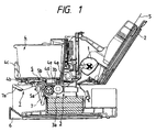
- a sheet supply roller 1 rotatingly driven by a motor cooperates with a separation pawl (not shown) to separate sheets S rested on a supply tray 2 one by one from an uppermost one.
- the supplied sheet S is conveyed to a recording position by means of a drive convey roller 3a and a driven roller 3b for urging the sheet S against the drive convey roller.
- These rollers 3a, 3b constitute a convey means 3.
- a recording means 4 serve to record an ink image on the sheet S conveyed by the convey means in an ink jet recording manner.
- the recording means 4 is of ink jet recording type.
- a recording head 4a is mounted on a carriage 4c reciprocally shiftable along a guide shaft 4a extending in a sheet width-wise direction and a guide rail 4b. While the recording head 4d is being driven in synchronous with the reciprocal movement of the carriage 4c, by discharging ink droplet toward the sheet S (a back surface of which is supported by a platen 4e) in response to an image signal, the ink image is formed on the sheet.
- the recording head 4d includes fine or small liquid discharge openings (orifices), liquid passages communicated with the respective discharge openings, energy acting portions disposed in the respective liquid passages, and energy generating means for generating liquid droplet forming energy in the liquid at the acting portions.
- the energy generating means may be used as a recording method utilizing electrical/mechanical converters such as piezo-electrical elements, a recording method utilizing energy generating means for generating heat by illuminating an electromagnetic wave such as laser and for discharging liquid droplets by action of the heat, or a recording method utilizing energy generating means for discharging liquid by heating the liquid by means of electrical/thermal converters such as heating elements having heating resistance body.
- recording heads used in an ink jet recording method for discharging ink by thermal energy since liquid discharge openings (orifices) for discharging recording ink droplets can be arranged with high density, the recording having high resolving power can be expected.
- recording heads having electrical/thermal converters used as the energy generating means can easily be made compact, can be mounted with high density and can be made cheaper.
- the recording head is designed so that the electrical/thermal converter is energized in response to a recording signal and the ink is discharged from the discharge opening by growth and contraction of a bubble generated in the ink by film-boiling caused by the thermal energy from the converter.
- the recording head 4d includes upper ink tanks for reserving inks, which ink tanks can be removably mounted on the carriage 4c.
- a discharge means 5 includes a drive discharge roller 5a and driven spur wheels 5b urging the sheet against the discharge roller and serves to discharge the sheet S (on which the image was formed) onto a discharge tray (discharge portion) 6 with the imaged surface facing upside.
- the spur wheel described herein means a rotary member having a small contact area (to the recording sheet S) so that, even when it is contacted with the imaged surface of the recording sheet, the ink image is not distorted.
- the support means 7 includes a plate-shaped support member 7a disposed above the discharge tray 6 and downstream of the discharge means 5 in a sheet conveying direction along an entire width of the sheet to support a non-imaged surface of the sheet S.
- the support member 7a can be rocked around a shaft 7b perpendicular to the sheet discharging direction.
- the support member is rocked by a driving force transmitted from a shift means (motor 8a and driving force transmitting unit 8b) between a support position shown by the solid line in Fig. 1 and a retard position shown by the two-dot and chain line.
- the support member 7a is shifted within a discharge tray space formed in the apparatus. Accordingly, since the support member does not provide an obstacle even at the support position, either the support position or the retard position can be selected as a home position. A length of the support member 7a is considerably shorter than a length of the tray 6 (extended condition).
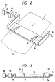
- a sheet support surface of the support member 7a is provided with two support ribs 7c spaced apart from each other by a predetermined distance.
- the ribs 7c are gradually protruded (inclined) from the sheet support surface of the support member 7a toward the sheet discharging direction.
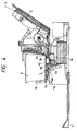
- the sheet $ is supported by the ribs 7c so that, as shown in Fig. 3 (schematic view looked at from the sheet discharging direction), a central portion Sb of the sheet becomes concave downwardly in comparison with both width-wise end portions Sa of the sheet.
- rigidity of the sheet S is increased, thereby preventing the tip end of the sheet from suspending.
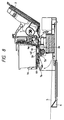
- the support member 7a is rotated to the support position to achieve a waiting condition for preparation for next discharge.
- the length of the support member 7a is selected to be smaller than a height between the tray 6 and the discharge portion.
- the sheet can be supported until the recording of the sheet is finished.
- the tip end of the sheet can be prevented from rubbing the imaged surface of the previous sheet already discharged on the tray 6, the ink image on the previous sheet is not distorted and the ink contamination does not occur.
- the support member 7a is positioned along the entire width of the sheet, regardless of the sheet width size, both large sheet and small sheet can be supported by the support member without making the apparatus bulky.
- ribs 7c are integrally formed with the support member 7a
- ribs may be formed from small wedge members independently from the support member, and the wedge members may be pivotally mounted on the support member and may be biased by elastic members such as springs for movement in an up-and-down direction so that the action of the ribs can be reduced when a hard sheet is discharged.
- FIG. 9 As a second embodiment of the present invention, another example of a support means will be explained with reference to Fig. 9. Incidentally, since elements other than the support means are the same as those in the first embodiment, explanation thereof will be omitted. Further, elements having the same function as that of the first embodiment are designated by the same reference numerals and explanation thereof will be omitted. This is true regarding other embodiments which will be described later.
- a support means 7 shown in Fig. 9 in place of the ribs 7c provided on the support member 7a of the first embodiment, two rotatable support rollers 7d are provided.
- a support means 7 shown in Fig. 10 in place of the support member 7a and the ribs 7c of the first embodiment, there are provided support arms 7e supported for pivotal movement and a hand-drum shaped rotary member 7f rotatably mounted on free ends of the support arms and capable of supporting the entire width of the sheet.
- this support means when the sheet S is discharged, the non-imaged surface of the sheet is supported by the rotary member 7f and the sheet S is curved in a concave shape by the hand-drum configuration of the rotary member 7f. In this condition, as the sheet is advanced, the rotary member 7f continues to support the sheet while rotating. Consequently, as is in the second embodiment, the sliding resistance to the sheet S is decreased. Further, the entire construction of the support means can be more simplified.
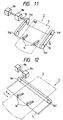
- a rotatable support belt 7g is provided in place of the support member 7a of the first embodiment.
- the support belt 7g is an endless belt having a width greater than the width of the sheet and mounted around drive pulleys 7h1 rotated by the motor 8a and driven pulleys 7h2 disposed downstream of the drive pulleys 7h1 in the sheet discharging direction. And, a portion of the endless belt other than portions directly associated with the pulleys 7h1, 7h2 is cut away or removed by about a half of an entire peripheral length to provide a cut-out portion 7g1. Further, two ribs 7i (corresponding to the ribs 7c in the first embodiment) are provided on the remaining portion of the support belt 7g at predetermined positions.
- the support belt 7g when the sheet S is discharged onto the support belt 7g, the non-imaged surface of the sheet is supported by the ribs 7i to curve the sheet in a concave shape. Then, after the recording, when the motor 8a is driven, the support belt 7g is rotated in a direction shown by the arrow A in Fig. 11. When the support belt 7g is rotated by about a half of the entire peripheral length, the cut-out portion 7g1 is opposed to the sheet not to support the sheet S, with the result that the sheet S is dropped onto the discharge tray 6. Thereafter, when the support belt 7g is further rotated in the direction A by the remaining peripheral length (one revolution in total) to return the belt to the initial position (waiting condition) where a next sheet can be supported by the ribs 7i.
- a rotatable support belt 7j similar to that of the fourth embodiment is used, but a rotational direction of the support belt differs from that of the support belt in the fourth embodiment by 90 degrees.
- the support belt is an endless belt mounted around a drive pulley 7k1 rotated by the motor 8a and a driven pulley 7k2 spaced apart from the pulley 7k1 by a distance greater than the width of the sheet.
- a portion of the endless belt other than a portion directly associated with the pulleys 7k1, 7k2 is cut away or removed by about a half of an entire peripheral length to provide a cut-out portion.
- two ribs 7n are provided on the remaining portion of the support belt 7j at predetermined positions.
- the support belt 7j when the sheet S is discharged onto the support belt 7j, the non-imaged surface of the sheet is supported by the ribs 7n to curve the sheet in a concave shape. Then, after the recording, when the motor 8a is driven, the support belt 7j is rotated in a direction shown by the arrow B or C in Fig. 12. When the support belt 7j is rotated by about a half of the entire peripheral length, the sheet S is not supported by the support belt, with the result that the sheet S is dropped onto the discharge tray 6. Thereafter, when the support belt 7j is further rotated by the remaining peripheral length (one revolution in total) to return the belt to the initial position (waiting condition) where a next sheet can be supported by the ribs 7n.
- the same advantage as that obtained in the fourth embodiment can be expected, and the stop position of the belt 7j can be adjusted to change the position of the ribs 7n for supporting the sheet S, thereby permitting fine adjustment for various sheets having different size.
- the belts 7j, 7g used in the fifth and fourth embodiments may be formed from elastic material such as rubber, material including filaments therein or thin material having no rigidity. Further, the number of the pulleys is not limited to one pair or two pairs.
- a support member 9a for supporting the non-imaged surface of the sheet S through the entire width thereof is disposed above the discharge tray 6 at a downstream side of the discharge means 5 in the sheet conveying direction.
- the support member 9a can be rocked around shafts 9b perpendicular to the sheet discharging direction.
- the support member is rocked by a shift means (described later) between a support position shown by the solid line in Fig. 13 and a retard position shown by the two-dot and chain line.
- a sheet support surface of the support member 9a is curved in a concave shape along the width-wise direction of the sheet.
- A, rotary member 9c acting as a biasing means (spur wheel in the illustrated embodiment) is rotatably supported above the support member 9a at a central position of the width of the sheet.
- the spur wheel 9c is supported on a holder 9e to be biased downwardly by a spring 9d, thereby biasing the imaged surface of the discharged sheet S substantially downwardly in a vertical direction (toward the support member 9a). Due to such a biasing action, as shown by the two-dot and chain line in Fig.
- the sheet S discharged while being supported by the support means 9 is curved in a concave shape along the curved surface of the support member 9a.
- the holder 9c is secured to a back surface of the guide rail 4b.
- the rigidity of the discharged sheet S is increased, with the result that the sheet S is advanced in the sheet discharging direction without suspending the tip end of the sheet downwardly.
- the tip end of the sheet does not directly contact with the previous sheet S rested on the discharge tray 6 not to distort the ink image on the previous sheet.
- the support member 9a has the continuous concave configuration along the width-wise direction of the sheet S, even when a sheet having a different size (for example, a sheet having a width smaller than that of the sheet S shown in Fig. 14) is used, as is in the sheet S, a concave shape is formed in the sheet to increase the rigidity thereof. Accordingly, even when various sheets having different size are used, any sheet can be advanced without suspending a tip end of the sheet downwardly, thereby preventing the tip end of the sheet from rubbing the imaged surface of the previous sheet S to prevent the ink image on the previous sheet.
- a sheet having a different size for example, a sheet having a width smaller than that of the sheet S shown in Fig. 14
- the support member 9a is shifted to the position shown by the two-dot and chain line in Fig. 13, the non-imaged surface of the sheet is not supported, with the result that the sheet S is dropped onto the discharge tray 6 by its own weight. Thus, the sheet stacking ability is not worsened.
- the support member 9a is returned to a waiting position shown by the solid line in Fig. 13.
- the tip end of the sheet S can be prevented from rubbing the imaged surface of the previous sheet already discharged on the discharge tray 6 until the recording is finished.
- the ink image of the previous sheet discharged on the discharge tray 6 is not distorted and the ink contamination can be prevented.
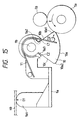
- the shift means includes driving force transmitting portions 10 each having a cam portion 10a having a pivot center coaxial with the shaft 9b for the support member 9a and capable of transmitting a driving force to the support member 9a to rock the support member between the support position and the retard position, and springs 11 disposed between the support member 9a and the driving force transmitting portions 10.
- Each cam portion 10a has a circular arc profile centered at the respective shaft 9b, and a radius of the cam profile is substantially equal to a distance between the shaft 9b and a peripheral surface of the corresponding discharge roller portion 5a.
- Fig. 15 shows a sheet supporting condition.
- the support member 9a is biased toward a direction D1 by the springs 11 via stopper portions 9a1 of the support member 9a to be abutted against the guide rail 4b.
- the support member 9a is maintained in the sheet supporting condition.
- the discharge roller 5a is rotated in a direction shown by the arrow E during the recording, since only the weight of the support member 9a acts on the discharge roller 5a as an abutting force, the sheet supporting condition can be maintained.
- the discharge roller 5a is rotated in a direction shown by the arrow F in Fig. 16 in order to retard the support member 9a.
- the driving force transmitting portion 10 is rotated in a direction shown by the arrow G until a gap C1 (refer to Fig. 15) formed between the support member 9a and the driving force transmitting portion 10 due to the abutment between one end 10a1 of the cam portion 10a and the discharge roller 5a is disappeared.
- a gap C1 (refer to Fig. 15) formed between the support member 9a and the driving force transmitting portion 10 due to the abutment between one end 10a1 of the cam portion 10a and the discharge roller 5a is disappeared.
- an abutment portion 10b of the driving force transmitting portion 10 is engaged by an abutment portion 9a2 of the support member 9a, the support member 9a starts to rotated in the direction G.
- the support member 9a is further rotated until the cam portion 10a of the driving force transmitting portion 10 leaves the discharge roller. Then, the other end 10a2 of the cam portion 10 abuts against the discharge roller 5a by the weight of the support member 9a, thereby maintaining the support member 9a in the retard position.
- the discharge roller 5a is rotated in the direction E.
- the driving force transmitting portion 10 is rotated in a direction shown by the arrow H until a gap (C1 + C2) (refer to Fig. 17) formed between the support member 9a and the driving force transmitting portion 10 is disappeared.
- the driving force transmitting portions 10 for shifting the support member 9a between the support position and the retard position are formed independently from the support member 9a and the springs 11 for biasing the driving force transmitting portions 10 away from the support member 9a are also provided.
- the same advantage as those in the aforementioned embodiments can be expected, and any special drive source for shifting the support member 9a can be omitted.
- a seventh embodiment of the present invention a further example of a support means will be explained with reference to Fig. 19 (view looked at from the sheet discharging direction).
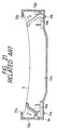
- a support member 9a extends through the entire width of the sheet S, and a sheet support surface of the support member is curved to provide two concave portions disposed on both sides of the central position of the sheet width-wise direction. Further, biasing spur wheels 9c are positioned above the deepest points of the concave portions.
- the support means according to this embodiment is effective particularly when a large size sheet is used. That is to say, in order to provide the concave surface in the large size sheet to advance the sheet in the sheet discharging direction without contacting with the previous sheet already discharged on the discharge tray 6, a curved amount of the concave surface may be increased. However, in this case, the entire apparatus will become bulky. To the contrary, in the illustrated embodiment, since the curved amount can be minimized by increasing the number of the concave surfaces, the apparatus does not become bulky.
- ribs 9f are provided on the support member 9a in the vicinity of both end portions S1, S2 of the sheet S in the sheet width-wise direction.
- the entire apparatus does not bulky and various sheets can be handled.
- the sheet may be curved to provide convex surface(s). Further, in the above-mentioned embodiments, while an example that the sheet S is curved to provide the continuous concave surface having a radius of curvature was explained, the sheet may be curved to provide concave or convex surface defined by straight lines.
- the number of the ribs is not limited to two, but, three or more ribs having different height may be used to curve the sheet S.
- a single rib may be provided in the vicinity of one of both end portions of the sheet and a curved surface (such as shown in the sixth and seventh embodiments) may be provided on the support member in the vicinity of the other end portion of the sheet (combination of rib and concave surface) to increase the rigidity of the sheet.
- the ink jet recording head is used as the recording means.
- the reason is that the usage of the support means according to the embodiments of the present invention is most effective to prevent the distortion of the ink image formed by the ink jet recording head. Therefore, of course, other recording heads such as an electrophotographic recording head, a heat-transfer recording head and the like can be used.
- the sheet convey means 3 and the sheet discharge means 5 are constituted by the rollers
- these means may be constituted by rotating belts for applying a conveying force to the sheet.
- the sheet convey means 3 and the sheet discharge means 5 are provided independently was explained, the sheet convey means and the sheet discharge means may be integrally constituted by using a common roller and the like.
- the present invention provides an image forming apparatus in which an imaged sheet is discharged onto a stacking portion, comprising a recording means for forming an image on a sheet, a discharge means for discharging a sheet on which the image was formed onto the stacking portion, a support means disposed downstream of the discharge means in a sheet discharging direction along a width-wise direction of the sheet to be discharged to support one surface of the sheet, and a shift means for shifting the support means between a support position to support the sheet to be discharged above the stacking portion and a retard position not to support the sheet.
Landscapes
- Pile Receivers (AREA)
- Ink Jet (AREA)
- Handling Of Cut Paper (AREA)
- Handling Of Continuous Sheets Of Paper (AREA)
- Delivering By Means Of Belts And Rollers (AREA)
- Separation, Sorting, Adjustment, Or Bending Of Sheets To Be Conveyed (AREA)
- Feeding Of Articles By Means Other Than Belts Or Rollers (AREA)
- Discharge By Other Means (AREA)
Applications Claiming Priority (3)
| Application Number | Priority Date | Filing Date | Title |
|---|---|---|---|
| JP9103596 | 1996-04-12 | ||
| JP91035/96 | 1996-04-12 | ||
| JP8091035A JP2896339B2 (ja) | 1996-04-12 | 1996-04-12 | 画像形成装置 |
Publications (3)
| Publication Number | Publication Date |
|---|---|
| EP0800924A2 true EP0800924A2 (de) | 1997-10-15 |
| EP0800924A3 EP0800924A3 (de) | 1998-08-12 |
| EP0800924B1 EP0800924B1 (de) | 2002-12-04 |
Family
ID=14015258
Family Applications (1)
| Application Number | Title | Priority Date | Filing Date |
|---|---|---|---|
| EP97106003A Expired - Lifetime EP0800924B1 (de) | 1996-04-12 | 1997-04-11 | Bilderzeugungsgerät mit verbesserter Bogenausgabevorrichtung |
Country Status (4)
| Country | Link |
|---|---|
| US (1) | US5890822A (de) |
| EP (1) | EP0800924B1 (de) |
| JP (1) | JP2896339B2 (de) |
| DE (1) | DE69717527T2 (de) |
Families Citing this family (14)
| Publication number | Priority date | Publication date | Assignee | Title |
|---|---|---|---|---|
| JP3382501B2 (ja) * | 1997-05-15 | 2003-03-04 | キヤノン株式会社 | 画像形成装置 |
| JP3609638B2 (ja) * | 1999-02-23 | 2005-01-12 | シャープ株式会社 | インクジェットプリンターの排紙機構 |
| JP2001233527A (ja) * | 2000-02-22 | 2001-08-28 | Riso Kagaku Corp | 排紙装置及び印刷装置 |
| KR100472482B1 (ko) * | 2002-11-27 | 2005-03-09 | 삼성전자주식회사 | 기록매체의 배출기구 및 그를 구비한 잉크젯 프린터 |
| JP2005094477A (ja) * | 2003-09-18 | 2005-04-07 | Seiko Epson Corp | 透過原稿搬送装置及び画像読み取り装置 |
| JP2005247546A (ja) * | 2004-03-05 | 2005-09-15 | Brother Ind Ltd | 排出ローラ、搬送装置、及びインクジェット記録装置 |
| US7246962B2 (en) * | 2005-07-29 | 2007-07-24 | Lexmark International, Inc. | Exit roller system for an imaging apparatus |
| JP5286636B2 (ja) * | 2005-12-27 | 2013-09-11 | 新日鐵住金株式会社 | 加熱された金属板材の搬送装置および搬送方法 |
| JP2007292904A (ja) * | 2006-04-24 | 2007-11-08 | Ricoh Co Ltd | 画像形成装置 |
| JP2007204281A (ja) * | 2007-03-23 | 2007-08-16 | Ricoh Elemex Corp | シートスタック装置 |
| JP5796345B2 (ja) * | 2011-05-13 | 2015-10-21 | セイコーエプソン株式会社 | 紙排出装置、紙排出方法、およびプリンター |
| JP2015058565A (ja) * | 2013-09-17 | 2015-03-30 | ブラザー工業株式会社 | テープ印字装置 |
| JP6248599B2 (ja) * | 2013-12-13 | 2017-12-20 | セイコーエプソン株式会社 | 印刷装置 |
| EP3386768B1 (de) * | 2015-12-09 | 2020-07-15 | Hewlett-Packard Development Company, L.P. | Medienablage und drucker mit rampe, und verfahren zur kollisionsverhinderung |
Family Cites Families (15)
| Publication number | Priority date | Publication date | Assignee | Title |
|---|---|---|---|---|
| JPS4912784Y1 (de) * | 1969-03-12 | 1974-03-28 | ||
| JPS5931246A (ja) * | 1982-08-11 | 1984-02-20 | Shinwa:Kk | 板状体積み重ね装置 |
| JPS61211265A (ja) * | 1985-03-14 | 1986-09-19 | Eikou:Kk | 印刷物の積重ね装置 |
| JPS634946U (de) * | 1986-06-27 | 1988-01-13 | ||
| US4794859A (en) * | 1987-10-23 | 1989-01-03 | Hewlett-Packard Company | Active paper drop for printers |
| JPH01235657A (ja) * | 1988-03-17 | 1989-09-20 | Canon Inc | 印字装置 |
| US4844633A (en) * | 1988-06-24 | 1989-07-04 | Hewlett-Packard Company | Active paper drop mechanism for a printer |
| JPH03143865A (ja) * | 1989-10-27 | 1991-06-19 | Canon Inc | 記録装置における排紙スタッカ |
| CH687324A5 (fr) * | 1992-02-10 | 1996-11-15 | Bobst Sa | Cadre de support momentané d'un élément en plaque horizontal au sein d'une machine. |
| FR2688205B1 (fr) * | 1992-03-03 | 1994-04-15 | Cga Hbs Cie Gle Automatisme | Systeme de manipulation d'objets notamment pour machine de tri automatique de courrier. |
| JP3234009B2 (ja) * | 1992-09-25 | 2001-12-04 | 株式会社リコー | 画像記録装置 |
| US5324020A (en) * | 1992-09-29 | 1994-06-28 | Hewlett-Packard Company | Paper stacking system for printers |
| JP3267382B2 (ja) * | 1993-05-17 | 2002-03-18 | 理想科学工業株式会社 | 薄葉体積載受容装置 |
| JPH0760938A (ja) * | 1993-08-23 | 1995-03-07 | Riso Kagaku Corp | シート搬送装置 |
| US5603493A (en) * | 1994-12-03 | 1997-02-18 | Hewlett Packard Company | System for use in handling media |
-
1996
- 1996-04-12 JP JP8091035A patent/JP2896339B2/ja not_active Expired - Fee Related
-
1997
- 1997-04-10 US US08/838,809 patent/US5890822A/en not_active Expired - Fee Related
- 1997-04-11 DE DE69717527T patent/DE69717527T2/de not_active Expired - Fee Related
- 1997-04-11 EP EP97106003A patent/EP0800924B1/de not_active Expired - Lifetime
Also Published As
| Publication number | Publication date |
|---|---|
| JP2896339B2 (ja) | 1999-05-31 |
| US5890822A (en) | 1999-04-06 |
| EP0800924B1 (de) | 2002-12-04 |
| DE69717527D1 (de) | 2003-01-16 |
| EP0800924A3 (de) | 1998-08-12 |
| JPH09278255A (ja) | 1997-10-28 |
| DE69717527T2 (de) | 2003-04-17 |
Similar Documents
| Publication | Publication Date | Title |
|---|---|---|
| US5890822A (en) | Image forming apparatus | |
| US5564847A (en) | Media handling in an ink-jet printer having guide ribs | |
| EP0313208B1 (de) | Mechanismus für die Papierlage im Tintenstrahldrucker | |
| US6503011B2 (en) | Recording apparatus | |
| US6877854B2 (en) | Image forming apparatus | |
| CN101130314A (zh) | 记录设备 | |
| US6048060A (en) | Printing medium discharge apparatus used in an ink jet printer | |
| US6616361B2 (en) | Ink jet recording apparatus | |
| JP3762155B2 (ja) | 排紙装置及びこれを備えた画像形成装置 | |
| JPH08174947A (ja) | カール矯正装置およびこれを備えたプリンタ | |
| US6120143A (en) | Apparatus for holding a printing medium on a rotary drum and ink jet printer using the same | |
| JPH05185680A (ja) | 記録装置 | |
| EP0875390B1 (de) | Tintenstrahldruckvorrichtung | |
| EP0719651B1 (de) | Gerät zum Befördern von Blättern | |
| US5883655A (en) | Copy sheet stacking apparatus with articulated exit guide ramp | |
| JP7077741B2 (ja) | カール矯正装置及びこれを備えた画像形成装置 | |
| US6285854B1 (en) | Image recording apparatus | |
| EP0729842B1 (de) | Medientransport bei einem Tintenstrahldrucker | |
| EP0878312B1 (de) | Bilderzeugungsgerät mit Stützmitteln zum Stützen von Ausgabeblättern | |
| US4870432A (en) | Ink-jet printing apparatus and film nozzle member used in the same | |
| JP3507236B2 (ja) | 記録装置 | |
| GB2290262A (en) | Paper handling in ink jet printer. | |
| JP2003266858A (ja) | キャリッジ | |
| JPH0613234B2 (ja) | 感熱式プリンタ | |
| JP7077740B2 (ja) | カール矯正装置及びこれを備えた画像形成装置 |
Legal Events
| Date | Code | Title | Description |
|---|---|---|---|
| PUAI | Public reference made under article 153(3) epc to a published international application that has entered the european phase |
Free format text: ORIGINAL CODE: 0009012 |
|
| AK | Designated contracting states |
Kind code of ref document: A2 Designated state(s): DE FR GB IT |
|
| PUAL | Search report despatched |
Free format text: ORIGINAL CODE: 0009013 |
|
| AK | Designated contracting states |
Kind code of ref document: A3 Designated state(s): DE FR GB IT |
|
| 17P | Request for examination filed |
Effective date: 19981229 |
|
| 17Q | First examination report despatched |
Effective date: 19991129 |
|
| GRAG | Despatch of communication of intention to grant |
Free format text: ORIGINAL CODE: EPIDOS AGRA |
|
| GRAG | Despatch of communication of intention to grant |
Free format text: ORIGINAL CODE: EPIDOS AGRA |
|
| GRAG | Despatch of communication of intention to grant |
Free format text: ORIGINAL CODE: EPIDOS AGRA |
|
| GRAH | Despatch of communication of intention to grant a patent |
Free format text: ORIGINAL CODE: EPIDOS IGRA |
|
| GRAH | Despatch of communication of intention to grant a patent |
Free format text: ORIGINAL CODE: EPIDOS IGRA |
|
| GRAA | (expected) grant |
Free format text: ORIGINAL CODE: 0009210 |
|
| AK | Designated contracting states |
Kind code of ref document: B1 Designated state(s): DE FR GB IT |
|
| REG | Reference to a national code |
Ref country code: GB Ref legal event code: FG4D |
|
| REF | Corresponds to: |
Ref document number: 69717527 Country of ref document: DE Date of ref document: 20030116 |
|
| ET | Fr: translation filed | ||
| PLBE | No opposition filed within time limit |
Free format text: ORIGINAL CODE: 0009261 |
|
| STAA | Information on the status of an ep patent application or granted ep patent |
Free format text: STATUS: NO OPPOSITION FILED WITHIN TIME LIMIT |
|
| 26N | No opposition filed |
Effective date: 20030905 |
|
| PGFP | Annual fee paid to national office [announced via postgrant information from national office to epo] |
Ref country code: GB Payment date: 20060405 Year of fee payment: 10 |
|
| PGFP | Annual fee paid to national office [announced via postgrant information from national office to epo] |
Ref country code: DE Payment date: 20060406 Year of fee payment: 10 |
|
| PGFP | Annual fee paid to national office [announced via postgrant information from national office to epo] |
Ref country code: FR Payment date: 20060410 Year of fee payment: 10 |
|
| PGFP | Annual fee paid to national office [announced via postgrant information from national office to epo] |
Ref country code: IT Payment date: 20060430 Year of fee payment: 10 |
|
| GBPC | Gb: european patent ceased through non-payment of renewal fee |
Effective date: 20070411 |
|
| PG25 | Lapsed in a contracting state [announced via postgrant information from national office to epo] |
Ref country code: DE Free format text: LAPSE BECAUSE OF NON-PAYMENT OF DUE FEES Effective date: 20071101 |
|
| PG25 | Lapsed in a contracting state [announced via postgrant information from national office to epo] |
Ref country code: GB Free format text: LAPSE BECAUSE OF NON-PAYMENT OF DUE FEES Effective date: 20070411 |
|
| PG25 | Lapsed in a contracting state [announced via postgrant information from national office to epo] |
Ref country code: FR Free format text: LAPSE BECAUSE OF NON-PAYMENT OF DUE FEES Effective date: 20070430 |
|
| PG25 | Lapsed in a contracting state [announced via postgrant information from national office to epo] |
Ref country code: IT Free format text: LAPSE BECAUSE OF NON-PAYMENT OF DUE FEES Effective date: 20070411 |