EP0800958A2 - Gassack-Schutzvorrichtung für normale Entfaltungen und Entfaltungen bei einer inkorrekten Position des Insassen - Google Patents
Gassack-Schutzvorrichtung für normale Entfaltungen und Entfaltungen bei einer inkorrekten Position des Insassen Download PDFInfo
- Publication number
- EP0800958A2 EP0800958A2 EP97302178A EP97302178A EP0800958A2 EP 0800958 A2 EP0800958 A2 EP 0800958A2 EP 97302178 A EP97302178 A EP 97302178A EP 97302178 A EP97302178 A EP 97302178A EP 0800958 A2 EP0800958 A2 EP 0800958A2
- Authority
- EP
- European Patent Office
- Prior art keywords
- flap
- base panel
- air bag
- tether
- gas
- Prior art date
- Legal status (The legal status is an assumption and is not a legal conclusion. Google has not performed a legal analysis and makes no representation as to the accuracy of the status listed.)
- Granted
Links
- 238000013022 venting Methods 0.000 claims abstract description 29
- 239000000463 material Substances 0.000 claims abstract description 16
- 238000000034 method Methods 0.000 claims abstract description 8
- 230000035699 permeability Effects 0.000 claims description 30
- 239000004744 fabric Substances 0.000 claims description 5
- 238000006073 displacement reaction Methods 0.000 claims description 4
- 239000007789 gas Substances 0.000 description 18
- 238000010276 construction Methods 0.000 description 5
- 238000004519 manufacturing process Methods 0.000 description 3
- 230000001681 protective effect Effects 0.000 description 2
- 208000027418 Wounds and injury Diseases 0.000 description 1
- 239000011248 coating agent Substances 0.000 description 1
- 238000000576 coating method Methods 0.000 description 1
- 230000006378 damage Effects 0.000 description 1
- 208000014674 injury Diseases 0.000 description 1
- 238000009434 installation Methods 0.000 description 1
- 230000002093 peripheral effect Effects 0.000 description 1
- 230000002787 reinforcement Effects 0.000 description 1
- 238000007789 sealing Methods 0.000 description 1
- 239000002759 woven fabric Substances 0.000 description 1
Images
Classifications
-
- B—PERFORMING OPERATIONS; TRANSPORTING
- B60—VEHICLES IN GENERAL
- B60R—VEHICLES, VEHICLE FITTINGS, OR VEHICLE PARTS, NOT OTHERWISE PROVIDED FOR
- B60R21/00—Arrangements or fittings on vehicles for protecting or preventing injuries to occupants or pedestrians in case of accidents or other traffic risks
- B60R21/02—Occupant safety arrangements or fittings, e.g. crash pads
- B60R21/16—Inflatable occupant restraints or confinements designed to inflate upon impact or impending impact, e.g. air bags
- B60R21/23—Inflatable members
- B60R21/239—Inflatable members characterised by their venting means
-
- B—PERFORMING OPERATIONS; TRANSPORTING
- B60—VEHICLES IN GENERAL
- B60R—VEHICLES, VEHICLE FITTINGS, OR VEHICLE PARTS, NOT OTHERWISE PROVIDED FOR
- B60R21/00—Arrangements or fittings on vehicles for protecting or preventing injuries to occupants or pedestrians in case of accidents or other traffic risks
- B60R21/02—Occupant safety arrangements or fittings, e.g. crash pads
- B60R21/16—Inflatable occupant restraints or confinements designed to inflate upon impact or impending impact, e.g. air bags
- B60R21/23—Inflatable members
- B60R21/231—Inflatable members characterised by their shape, construction or spatial configuration
- B60R21/233—Inflatable members characterised by their shape, construction or spatial configuration comprising a plurality of individual compartments; comprising two or more bag-like members, one within the other
Definitions
- This invention relates to vehicle air bag cushions, and more particularly to occupant protection during both normal and out of position occupant deployments.
- the present invention offers a novel method and simplified construction to protect against undesired full pressure deployment in the event that an obstruction such as an out of position occupant is encountered by the face panel of an air bag cushion during deployment.
- An excess venting capability is allowed to remain in operative condition in the event that such an obstruction exists; however, if an obstruction is not detected, the amount of venting which is deemed excessive is blocked off by hinged flaps which are urged into a closing position under the influence of the deployment gas flow.
- the amount of venting to accomplish both the normal FMVSS 208 deployment and a protective deployment can be achieved by controlling the size of both the large venting area for protective deployment and the smaller venting area for normal deployment with precision and reduced manufacturing costs.
- Reliability of performance is enhanced by the use of hinge mounted flaps which swing from an open position to a closed position by becoming unattached from a connection to the face panel as it deploys past a predetermined position along its path toward an occupant in a normal occupant seating position.
- a preferred apparatus employs two or four flaps, although a single flap could be used.
- Each flap is secured to the base panel by stitches disposed peripherally around the opening for receiving the inflation gas.
- a free end of each flap is mounted for swinging movement about the stitches which serve as a hinge line and is attached to move with the face panel as by means of a tether.
- the tether is secured at one end to the face panel and at its other end to the base panel; the free end of a respective flap is releasably attached at a point intermediate the ends of the tether with the distance between the attachment point and the base panel securement stitch as measured along the tether being greater than the same distance as measured along the flap.
- the air bag cushion has a face panel 10 that is adapted to contact a vehicle passenger seated in an occupant seating area and a base panel 12 which is secured to the vehicle at a position from where inflation gas is supplied when deployment of the air bag cushion is desired.
- Panels 10 and 12 have low gas permeability, which can be accomplished by use of low permeability fabrics or through coating.
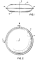
- the outer peripheral edges of face panel 10 and base panel 12 may be joined together in a conventional manner as by stitches 14, see Fig. 1-3 to define the perimeter of the cushion. In Fig. 2, only half of the cushion is shown. The cushion is symmetrical about the centerline 8.
- the face panel 10 and the base panel 12 may be cut to have two openings 18 and 20 approximately the same size and shape.
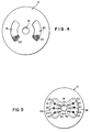
- the base panel 12 is shown in Fig. 4 to have a conventional inflation gas receiving opening defined by wall 16 and two high permeability areas 18 and 20 where the low permeability material has been removed. Areas 18 and 20 preferably are symmetrically disposed with respect to inflation gas opening 16. High permeability areas 18 and 20 are preferably covered by a suitable open woven fabric such as high permeability screens 22 mounted on an inside surface of base panel 12. The amount of high permeability area may vary as one or more continuous areas may be used for venting or a number of conventional unscreened cuts which serve as vents may be provided.
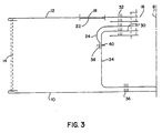
- the cushion is normally built with several doublers (see Fig. 3).
- One of these doublers which is formed of a low permeability material, includes a hinged flap 24 associated with area 18 and hinged flap 26 is associated with area 20 as indicated in Fig. 5.
- flaps 24 and 26 have a shape and size to fully cover their respective high permeability areas 18, 20 shown in Fig. 4 and are preferably provided with vent holes 28 shown in Fig. 5.
- the areas of vent holes 28 may be controlled with precision which simplifies achieving the exacting conditions for a normal deployment.
- the total area of the high permeability regions 18 and 20 may be precisely controlled, or even made into a single area.
- the flaps 24 and 26 can be smaller than regions 18 and 20 and subtract a precisely controlled area by being made of a high permeability material without vent holes 28.
- Flaps 24 and 26 are conveniently formed from a single piece of low permeability material, cut as indicated in Fig. 5 and located on the same side of the base panel 12 as the screens 22.
- the central portion 30 may be an integral part of the flaps 24 and 26 and be secured by stitches 32 around the periphery of the wall 16 which defines the central opening 16 through which inflation gas is received.
- Two tethers 34 (only one is illustrated in Fig. 3), located on the same side of the base panel 12 as the screens 22, are attached by stitches 32 at one end to the base panel 12 and by stitches 36 at the other end to the face panel 10 as illustrated.
- Four tethers could be used.
- the flaps 24, 26 of Figs. 3 and 5 have one end secured by the stitches 32 that surround central opening 16 and may be sandwiched between the base panel 12, the central portion 30 of the tethers 34 and other layers which provide reinforcement around central opening 16.
- the free ends 38 of the flaps 24, 26 are attached at intermediate position 40 along the lengths of their respective tethers 34.
- the attach point at the intermediate position 40 is designed to come apart as tether 34 is placed under tension by reason of the face panel 10 passing a predetermined position without being obstructed.
- the flap free end 38 of the flap moves away from the tether 34 and is propelled toward the high permeability area 18 or screen 22 by the inflation gas flow toward the exterior of the air bag cushion.
- the distance between the attach point 40 and the stitches 32 as measured along the flap 24 is less than the same distance as measured along the tether 34.
- tension in tether 34 between stitches 36 and attach point 40 increases without placing a tension load on that portion of the tether 34 between attach point 40 and the stitches. Instead, the tension force on the flap 24 increases.
- the stitch strength at attach point 40 is very low, as indicated by the single line 40, when compared with the strength of the stitches at seams 32, 36 and indicated by three lines, the attach point 40 separates and comes apart as the face panel 10 passes a predetermined position.
- the predetermined position may be chosen by the selection of the location of the attach point 40 on tether 34. If the flap free end 38 is sufficiently long, the free end 38 may be directly attached to the face panel 10 by a weak seam that is bonded or stitched, thereby avoiding the requirement for attachment to a tether.
- the flap 24 is illustrated to have vent holes 28 similar to those in production cushions.
- the vent holes 28 are sized such that when the flap 24 totally covers the high permeability area screen 22, the exact amount of venting occurs to provide occupant protection during a normal deployment.
- the cushion will begin to open as normal.
- the face panel 10 will not travel to the end of the tethers 34, but will tend to stop when it hits an obstruction.
- the doublers or flaps 24, 26 will remain attached to the face panel 10 via the tethers 34 and allow the gases to vent through the very large areas of high permeability, and into the atmosphere. This allows the cushion to vent the gases to the atmosphere instead of filling the cushion and causing possible injury.
- the advantages of the present invention can be achieved by other constructions which are easy to manufacture by avoiding variables and allow precision in the determination of the venting ability of the gas permeable areas. Breaking a seam is controllable. A hinged flap is easier to control than a sliding flap.
- the base panel 10 could be essentially completely porous through much or all of its area, the flaps have a low permeability without vents and the size of the flap chosen with precision.
- the mechanics of deployment would be identical to the one described above, i.e. in the event the face panel does not encounter an obstruction, the flaps would release and be forced into position by the gas flow during deployment. This would restrict the amount of venting and cause the cushion to fill for a normal deployment.
- Another alternative construction is to provide a cushion with vents required for normal deployment that are placed in an area not covered by the flaps at any time during deployment. Additional vents are provided in the base panel which the flaps having a low permeability will cover during normal deployment. With the flaps held out of the way during an out-of-position deployment, the gases which would produce an undesired force on the obstruction, which in a passenger side installation may be an infant seat, will be vented from the cushion. During normal deployment, the flaps will be detached from the tethers and forced by the influence of the gas flow to cover the additional vents. In this case, the gases will pass only through the vents normally present and provide the normal occupant protection.
Landscapes
- Engineering & Computer Science (AREA)
- Mechanical Engineering (AREA)
- Air Bags (AREA)
Applications Claiming Priority (2)
| Application Number | Priority Date | Filing Date | Title |
|---|---|---|---|
| US08/629,128 US5669628A (en) | 1996-04-08 | 1996-04-08 | Air bag cushion protection during both normal and out of position deployments |
| US629128 | 1996-04-08 |
Publications (3)
| Publication Number | Publication Date |
|---|---|
| EP0800958A2 true EP0800958A2 (de) | 1997-10-15 |
| EP0800958A3 EP0800958A3 (de) | 1999-07-07 |
| EP0800958B1 EP0800958B1 (de) | 2003-01-08 |
Family
ID=24521699
Family Applications (1)
| Application Number | Title | Priority Date | Filing Date |
|---|---|---|---|
| EP97302178A Expired - Lifetime EP0800958B1 (de) | 1996-04-08 | 1997-03-27 | Gassack-Schutzvorrichtung für normale Entfaltungen und Entfaltungen bei einer inkorrekten Position des Insassen |
Country Status (4)
| Country | Link |
|---|---|
| US (1) | US5669628A (de) |
| EP (1) | EP0800958B1 (de) |
| JP (2) | JPH1029496A (de) |
| DE (1) | DE69718228T2 (de) |
Families Citing this family (24)
| Publication number | Priority date | Publication date | Assignee | Title |
|---|---|---|---|---|
| GB2323569B (en) * | 1997-03-24 | 2001-05-09 | Autoliv Dev | Improvements in or relating to an air-bag arrangement |
| JP3788033B2 (ja) * | 1998-05-29 | 2006-06-21 | タカタ株式会社 | エアバッグ装置 |
| DE19829000B4 (de) * | 1998-06-29 | 2005-06-02 | Peter Fassbaender | Verfahren zum Betreiben einer eine Druckgaseinrichtung mit einer Druckgaspatrone aufweisenden Fahrzeuginsassen-Rückhaltevorrichtung sowie eine Fahrzeuginsassen-Rückhaltevorrichtung mit einer eine Druckgaspatrone aufweisenden Druckgaseinrichtung |
| JP2000043674A (ja) * | 1998-07-29 | 2000-02-15 | Honda Motor Co Ltd | エアバッグ装置 |
| US6447006B1 (en) * | 2000-10-03 | 2002-09-10 | Autoliv Asp, Inc. | Inflatable curtain cushion vent |
| US6428042B1 (en) * | 2001-01-08 | 2002-08-06 | Trw Vehicle Safety Systems Inc. | Dual volume air bag with vent |
| US6517108B1 (en) * | 2002-01-02 | 2003-02-11 | Ford Global Technologies, Inc. | Pyrotechnic air bag stitch vent |
| US6736425B2 (en) | 2002-01-28 | 2004-05-18 | Ford Global Technologies, Llc | System for venting an air bag module |
| US6802528B2 (en) | 2002-04-05 | 2004-10-12 | Ford Global Technologies, Llc | Air bag cushion energy diverter |
| US6746045B2 (en) * | 2002-04-05 | 2004-06-08 | Ford Global Technologies, Llc | Air bag inflator gas venting system |
| JP4100129B2 (ja) * | 2002-10-28 | 2008-06-11 | タカタ株式会社 | エアバッグ装置 |
| GB2394919B (en) * | 2002-11-06 | 2006-01-25 | Autoliv Dev | Improvements in or relating to an air-bag arrangement |
| JP3982423B2 (ja) * | 2003-01-30 | 2007-09-26 | 豊田合成株式会社 | エアバッグ |
| JP4360525B2 (ja) * | 2003-07-02 | 2009-11-11 | 芦森工業株式会社 | エアバッグ装置 |
| DE102004009013B4 (de) * | 2004-02-25 | 2006-03-16 | Trw Automotive Gmbh | Seitenaufprall-Rückhaltevorrichtung |
| DE102004024405A1 (de) * | 2004-05-17 | 2005-12-15 | Trw Automotive Gmbh | Fußgängerschutzvorrichtung an einem Kraftfahrzeug |
| US7494151B2 (en) * | 2005-02-17 | 2009-02-24 | Tk Holdings Inc. | Airbag apparatus with adaptive inflation |
| US20060202456A1 (en) * | 2005-03-09 | 2006-09-14 | Takata Restraint Systems, Inc. | Curtain airbag with deflation mechanism |
| JP4523891B2 (ja) * | 2005-07-28 | 2010-08-11 | 本田技研工業株式会社 | エアバッグ装置 |
| JP5125490B2 (ja) * | 2007-12-26 | 2013-01-23 | トヨタ自動車株式会社 | エアバッグ装置 |
| JP5322275B2 (ja) * | 2009-02-06 | 2013-10-23 | タカタ株式会社 | エアバッグ装置 |
| DE102010007879A1 (de) * | 2010-02-13 | 2011-08-18 | Daimler AG, 70327 | Airbag sowie Verfahren zum Herstellen eines solchen Airbags |
| US10829082B2 (en) * | 2018-01-31 | 2020-11-10 | Nissan North America, Inc. | Airbag device |
| KR102139304B1 (ko) | 2018-10-26 | 2020-07-30 | 한국가스공사 | 가스감지기용 교정 장치 및 이를 이용한 교정 방법 |
Family Cites Families (15)
| Publication number | Priority date | Publication date | Assignee | Title |
|---|---|---|---|---|
| JPS5131658B2 (de) * | 1972-02-28 | 1976-09-08 | ||
| JPS5247233A (en) * | 1975-10-09 | 1977-04-14 | Honda Motor Co Ltd | Air bag |
| US4181325A (en) * | 1978-03-06 | 1980-01-01 | General Motors Corporation | Occupant restraint cushion |
| JP2945039B2 (ja) * | 1989-10-24 | 1999-09-06 | タカタ株式会社 | エアバッグ |
| JP2879233B2 (ja) * | 1989-12-27 | 1999-04-05 | 池田物産 株式会社 | エアバッグ装置 |
| US5211422A (en) * | 1991-08-29 | 1993-05-18 | General Motors Corporation | Occupant restraint system |
| US5226671A (en) * | 1991-10-17 | 1993-07-13 | Trw Inc. | Air bag structure and method of forming |
| US5249825A (en) * | 1992-07-13 | 1993-10-05 | General Motors Corporation | Air bag with releasable tethers |
| DE4223775C1 (de) * | 1992-07-18 | 1993-06-24 | Mercedes-Benz Aktiengesellschaft, 7000 Stuttgart, De | |
| JPH06199196A (ja) * | 1992-10-30 | 1994-07-19 | Takata Kk | エアバッグ |
| US5246250A (en) * | 1992-11-25 | 1993-09-21 | General Motors Corporation | Air bag valve assembly |
| US5280953A (en) * | 1992-11-25 | 1994-01-25 | General Motors Corporation | Displacement responsive air bag vent |
| US5405166A (en) * | 1993-07-30 | 1995-04-11 | Alliedsignal Inc. | Air bag with inflation limiter |
| US5492363A (en) * | 1994-09-07 | 1996-02-20 | Takata, Inc. | Flow regulating air bag valve |
| US5501488A (en) * | 1995-04-28 | 1996-03-26 | Morton International, Inc. | Airbag with alternate deployment modes |
-
1996
- 1996-04-08 US US08/629,128 patent/US5669628A/en not_active Expired - Lifetime
-
1997
- 1997-03-27 EP EP97302178A patent/EP0800958B1/de not_active Expired - Lifetime
- 1997-03-27 DE DE69718228T patent/DE69718228T2/de not_active Expired - Fee Related
- 1997-04-07 JP JP9087995A patent/JPH1029496A/ja active Pending
-
1999
- 1999-05-24 JP JP1999003576U patent/JP3064194U/ja not_active Expired - Lifetime
Also Published As
| Publication number | Publication date |
|---|---|
| JPH1029496A (ja) | 1998-02-03 |
| DE69718228D1 (de) | 2003-02-13 |
| JP3064194U (ja) | 1999-12-24 |
| DE69718228T2 (de) | 2003-11-13 |
| US5669628A (en) | 1997-09-23 |
| EP0800958A3 (de) | 1999-07-07 |
| EP0800958B1 (de) | 2003-01-08 |
Similar Documents
| Publication | Publication Date | Title |
|---|---|---|
| EP0800958B1 (de) | Gassack-Schutzvorrichtung für normale Entfaltungen und Entfaltungen bei einer inkorrekten Position des Insassen | |
| EP0710194B1 (de) | Luftsack mit aufblasbegrenzer | |
| US8500163B2 (en) | Airbag vent assembly | |
| JP2932666B2 (ja) | エアバッグ | |
| EP0611685B1 (de) | Insassen-Luftsackrückhaltevorrichtung | |
| US5524924A (en) | Method and apparatus for restraining an occupant of a vehicle upon a side impact against the vehicle | |
| EP0838377B1 (de) | Airbag-Bewegungsbegrenzungsband | |
| US5246250A (en) | Air bag valve assembly | |
| US7607689B2 (en) | Air bag vent with tether | |
| US5848804A (en) | Side impact air bag module | |
| US20070108750A1 (en) | Passive airbag venting | |
| US20080073890A1 (en) | Airbag cushion with a laced vent to optionally gas for out-of-position conditions | |
| US5492362A (en) | Airbag with controlled venting | |
| WO2008010885A1 (en) | Airbag with active exhaust vent | |
| DE102012009209B4 (de) | Insassenschutzvorrichtung mit aktiver Entlüftung | |
| US9821751B2 (en) | Airbag module | |
| JPH11222097A (ja) | 膨張可能ガスバックを有する車両乗員のための衝撃保護装置 | |
| US5562302A (en) | Inflatable vehicle occupant restraint | |
| KR101332718B1 (ko) | 팽창식 에어백 | |
| JP2010535121A (ja) | 車両搭乗者の保護のためのエアバッグ | |
| US11414043B2 (en) | Airbag with single panel vent flap | |
| JP2002079905A (ja) | 車両用エアバッグ装置 | |
| JP3971671B2 (ja) | 乗員拘束装置 | |
| JPH07329693A (ja) | エアバッグの内圧調節装置 | |
| KR102703549B1 (ko) | 차량용 에어백 장치 및 그 전개방법 |
Legal Events
| Date | Code | Title | Description |
|---|---|---|---|
| PUAI | Public reference made under article 153(3) epc to a published international application that has entered the european phase |
Free format text: ORIGINAL CODE: 0009012 |
|
| AK | Designated contracting states |
Kind code of ref document: A2 Designated state(s): DE FR GB IT |
|
| PUAL | Search report despatched |
Free format text: ORIGINAL CODE: 0009013 |
|
| AK | Designated contracting states |
Kind code of ref document: A3 Designated state(s): DE FR GB IT |
|
| 17P | Request for examination filed |
Effective date: 19991022 |
|
| 17Q | First examination report despatched |
Effective date: 20001017 |
|
| GRAG | Despatch of communication of intention to grant |
Free format text: ORIGINAL CODE: EPIDOS AGRA |
|
| GRAG | Despatch of communication of intention to grant |
Free format text: ORIGINAL CODE: EPIDOS AGRA |
|
| GRAH | Despatch of communication of intention to grant a patent |
Free format text: ORIGINAL CODE: EPIDOS IGRA |
|
| GRAH | Despatch of communication of intention to grant a patent |
Free format text: ORIGINAL CODE: EPIDOS IGRA |
|
| RAP1 | Party data changed (applicant data changed or rights of an application transferred) |
Owner name: AUTOLIV ASP, INC. |
|
| GRAA | (expected) grant |
Free format text: ORIGINAL CODE: 0009210 |
|
| RTI1 | Title (correction) |
Free format text: AIR BAG CUSHION PROTECTION DURING BOTH NORMAL AND OUT OF POSITION DEPLOYMENTS |
|
| AK | Designated contracting states |
Kind code of ref document: B1 Designated state(s): DE FR GB IT |
|
| PG25 | Lapsed in a contracting state [announced via postgrant information from national office to epo] |
Ref country code: IT Free format text: LAPSE BECAUSE OF FAILURE TO SUBMIT A TRANSLATION OF THE DESCRIPTION OR TO PAY THE FEE WITHIN THE PRE;WARNING: LAPSES OF ITALIAN PATENTS WITH EFFECTIVE DATE BEFORE 2007 MAY HAVE OCCURRED AT ANY TIME BEFORE 2007. THE CORRECT EFFECTIVE DATE MAY BE DIFFERENT FROM THE ONE RECORDED.SCRIBED TIME-LIMIT Effective date: 20030108 |
|
| REG | Reference to a national code |
Ref country code: GB Ref legal event code: FG4D |
|
| REF | Corresponds to: |
Ref document number: 69718228 Country of ref document: DE Date of ref document: 20030213 Kind code of ref document: P |
|
| ET | Fr: translation filed | ||
| PG25 | Lapsed in a contracting state [announced via postgrant information from national office to epo] |
Ref country code: DE Free format text: LAPSE BECAUSE OF NON-PAYMENT OF DUE FEES Effective date: 20031001 |
|
| PLBE | No opposition filed within time limit |
Free format text: ORIGINAL CODE: 0009261 |
|
| STAA | Information on the status of an ep patent application or granted ep patent |
Free format text: STATUS: NO OPPOSITION FILED WITHIN TIME LIMIT |
|
| 26N | No opposition filed |
Effective date: 20031009 |
|
| PGFP | Annual fee paid to national office [announced via postgrant information from national office to epo] |
Ref country code: FR Payment date: 20040318 Year of fee payment: 8 |
|
| PGFP | Annual fee paid to national office [announced via postgrant information from national office to epo] |
Ref country code: GB Payment date: 20040324 Year of fee payment: 8 |
|
| PG25 | Lapsed in a contracting state [announced via postgrant information from national office to epo] |
Ref country code: GB Free format text: LAPSE BECAUSE OF NON-PAYMENT OF DUE FEES Effective date: 20050327 |
|
| GBPC | Gb: european patent ceased through non-payment of renewal fee |
Effective date: 20050327 |
|
| PG25 | Lapsed in a contracting state [announced via postgrant information from national office to epo] |
Ref country code: FR Free format text: LAPSE BECAUSE OF NON-PAYMENT OF DUE FEES Effective date: 20051130 |
|
| REG | Reference to a national code |
Ref country code: FR Ref legal event code: ST Effective date: 20051130 |