EP0801176A2 - Unterwasservorrichting zum Eingraben von Kabeln mit verbesserter Vorrichtung zum Kabellegen - Google Patents
Unterwasservorrichting zum Eingraben von Kabeln mit verbesserter Vorrichtung zum Kabellegen Download PDFInfo
- Publication number
- EP0801176A2 EP0801176A2 EP97103875A EP97103875A EP0801176A2 EP 0801176 A2 EP0801176 A2 EP 0801176A2 EP 97103875 A EP97103875 A EP 97103875A EP 97103875 A EP97103875 A EP 97103875A EP 0801176 A2 EP0801176 A2 EP 0801176A2
- Authority
- EP
- European Patent Office
- Prior art keywords
- cable
- depressor
- depressor wheel
- burial machine
- machine
- Prior art date
- Legal status (The legal status is an assumption and is not a legal conclusion. Google has not performed a legal analysis and makes no representation as to the accuracy of the status listed.)
- Withdrawn
Links
Images



Classifications
-
- E—FIXED CONSTRUCTIONS
- E02—HYDRAULIC ENGINEERING; FOUNDATIONS; SOIL SHIFTING
- E02F—DREDGING; SOIL-SHIFTING
- E02F5/00—Dredgers or soil-shifting machines for special purposes
- E02F5/02—Dredgers or soil-shifting machines for special purposes for digging trenches or ditches
- E02F5/14—Component parts for trench excavators, e.g. indicating devices travelling gear chassis, supports, skids
-
- E—FIXED CONSTRUCTIONS
- E02—HYDRAULIC ENGINEERING; FOUNDATIONS; SOIL SHIFTING
- E02F—DREDGING; SOIL-SHIFTING
- E02F5/00—Dredgers or soil-shifting machines for special purposes
- E02F5/02—Dredgers or soil-shifting machines for special purposes for digging trenches or ditches
- E02F5/10—Dredgers or soil-shifting machines for special purposes for digging trenches or ditches with arrangements for reinforcing trenches or ditches; with arrangements for making or assembling conduits or for laying conduits or cables
- E02F5/104—Dredgers or soil-shifting machines for special purposes for digging trenches or ditches with arrangements for reinforcing trenches or ditches; with arrangements for making or assembling conduits or for laying conduits or cables for burying conduits or cables in trenches under water
-
- E—FIXED CONSTRUCTIONS
- E02—HYDRAULIC ENGINEERING; FOUNDATIONS; SOIL SHIFTING
- E02F—DREDGING; SOIL-SHIFTING
- E02F5/00—Dredgers or soil-shifting machines for special purposes
- E02F5/02—Dredgers or soil-shifting machines for special purposes for digging trenches or ditches
- E02F5/10—Dredgers or soil-shifting machines for special purposes for digging trenches or ditches with arrangements for reinforcing trenches or ditches; with arrangements for making or assembling conduits or for laying conduits or cables
- E02F5/104—Dredgers or soil-shifting machines for special purposes for digging trenches or ditches with arrangements for reinforcing trenches or ditches; with arrangements for making or assembling conduits or for laying conduits or cables for burying conduits or cables in trenches under water
- E02F5/106—Dredgers or soil-shifting machines for special purposes for digging trenches or ditches with arrangements for reinforcing trenches or ditches; with arrangements for making or assembling conduits or for laying conduits or cables for burying conduits or cables in trenches under water using ploughs, coulters, rippers
Definitions
- Underwater burial machines are used to bury communications cables in the sea bottom in an effort to protect the cables from damage. These machines plow a groove in the seabed beneath a body of water, and they simultaneously lay a cable into the groove which they have plowed. Burial machines use at least one plow blade to cut a groove into the seabed immediately in front of a cable laying mechanism. The cable is then placed into the groove thus formed in order that it will be somewhat beneath the surface of the seabed. After the cable has been laid into the groove, water pressure and underwater currents eventually cause the vertical walls of the groove to collapse and move sand and soil into the groove, thereby covering the cable and assisting in the overall burial operation.
- a new design approach has been disclosed which solves many of the problems heretofore associated with existing cable laying mechanisms for underwater burial machines.
- the new design uses an efficient configuration of a pivotally liftable depressor wheel, located within a cable feed shoe which tracks the groove cut by the plow.
- a pair of arcuate cable guides, one on each side of the depressor wheel, assist in the guidance of both cables and bodies, without permitting either to bind.
- a communications cable 22 is unspooled from a spool 24 on the vessel 18.
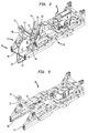
- a plow 26 cuts a groove 28 in the seabed 16, and the communications cable 22 is laid into the groove 28 by the cable laying apparatus 10 which is located on the rear of a carriage 30 which is fixed to the sled 14 using a four bar linkage 32.
- the four bar linkage 32 allows the carriage 30 to be moved up and down relative to the sled 12. This permits the plow 26 and cable laying apparatus 10, both of which are attached to the carriage 30, and both of which are shown to extend through the flat bottom of the sled 12, to be moved up and down relative to the bottom of the sled 12.
- the four bar linkage 32 allows the plow 26 and the cable laying apparatus 10 to be moved up above the bottom of the sled 12 when the sled 12 is recovered onto the deck of the vessel 18 for transportation or maintenance.
- the four bar linkage 32 can be used to adjust the depth of the groove 28 in the event that that becomes necessary due to the makeup of the seabed 16, i.e., if a rock layer is encountered below the surface of the seabed 16 at a depth which is less than the normal cable laying depth.
- the closed front of the feed shoe 42 forms an angle of about 30° with the seabed (See FIGS. 1 and 6), as this has been found to be the optimal angle for minimizing the collection of debris by the feed shoe 42.
- the top plate 40 has an elongated opening 46, which extends through the rear of the top plate 40, and a pair of elongated guide rail grooves 48, 50 are formed in the top plate 40.
- the cable 22 is fed through the openings 44, 46, and the elongated guide rail grooves 48, 50 are used to guide the depressor wheel assembly 36, when it is pivoted upward and out of the feed shoe 42, as will be explained below.
- a clevis 86 shown in FIG. 8, is attached to the bracket 58.
- a hydraulic cylinder 88 shown In FIG. 2, is attached to the carriage 30.
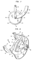
- a shaft (not shown) extends from the hydraulic cylinder 88 and attaches to the clevis 86. Accordingly, hydraulic pressure may be used to extend the shaft, whereby the depressor wheel assembly 36 will be pivoted upward and rearward relative to the sled 12 (around the axle 60) when a body 32 must be passed through the wheel assembly 36. This pivoting action removes the depressor wheel 52 from the rear of the feed shoe assembly 38, but the cable guides 62, 64 will continue to ride on their guide rails 63, 65, which remain in the guide rail grooves 48, 50 in the top plate 40.
- the wheel also has a series of magnets 70, 72 (FIG. 10), and 70, 74, 76, 78, 80, 82, 84 (FIG. 7) Installed around its rim. While eight magnets are illustrated, In the preferred embodiment of the invention, sixteen equally spaced magnets are presently used.
- the magnets 70-84 each cause a Hall effect sensor 68(FIG. 10), which is attached to bracket mounted on support brace 87, to generate an electrical signal as the depressor wheel 52 turns.
- the axle 54 includes a "METROX" load pin 55, manufactured by M/D Totco of Texas.
- This device 55 which is made of strain gauges, is able to measure the residual cable tension, which is the tension to which the cable 22 is subjected due to the weight of the cable 22 in the water, and other factors.
- the data from sensor 55 allows an operator on board the surface vessel 18 to monitor the tension on the cable 22.
- the particular sensor 55 which is used in the preferred embodiment of the invention is able to measure a tension of up to about 5,400 pounds, i.e. an amount far greater than that to which the cable 22 should ever be subjected.
Landscapes
- Engineering & Computer Science (AREA)
- Mining & Mineral Resources (AREA)
- Mechanical Engineering (AREA)
- Civil Engineering (AREA)
- General Engineering & Computer Science (AREA)
- Structural Engineering (AREA)
- Laying Of Electric Cables Or Lines Outside (AREA)
- Electric Cable Installation (AREA)
Applications Claiming Priority (2)
| Application Number | Priority Date | Filing Date | Title |
|---|---|---|---|
| US08/630,963 US5755530A (en) | 1996-04-08 | 1996-04-08 | Underwater cable burial machine having improved cable laying apparatus |
| US630963 | 1996-04-08 |
Publications (2)
| Publication Number | Publication Date |
|---|---|
| EP0801176A2 true EP0801176A2 (de) | 1997-10-15 |
| EP0801176A3 EP0801176A3 (de) | 1998-10-14 |
Family
ID=24529274
Family Applications (1)
| Application Number | Title | Priority Date | Filing Date |
|---|---|---|---|
| EP97103875A Withdrawn EP0801176A3 (de) | 1996-04-08 | 1997-03-07 | Unterwasservorrichting zum Eingraben von Kabeln mit verbesserter Vorrichtung zum Kabellegen |
Country Status (4)
| Country | Link |
|---|---|
| US (1) | US5755530A (de) |
| EP (1) | EP0801176A3 (de) |
| JP (1) | JPH1038143A (de) |
| CA (1) | CA2196818C (de) |
Cited By (2)
| Publication number | Priority date | Publication date | Assignee | Title |
|---|---|---|---|---|
| FR2772871A1 (fr) * | 1997-12-22 | 1999-06-25 | Adps Sa | Procede et dispositif de pose d'une structure allongee en fond de cours d'eau |
| WO2000014838A1 (en) * | 1998-09-03 | 2000-03-16 | Raytheon Company | Cable burial system |
Families Citing this family (8)
| Publication number | Priority date | Publication date | Assignee | Title |
|---|---|---|---|---|
| US6776559B1 (en) | 2002-09-30 | 2004-08-17 | Gulf Fiber Corporation | Method and apparatus for deploying a communications cable below the surface of a body of water |
| US20100262384A1 (en) * | 2009-04-07 | 2010-10-14 | Umair Marfani | High tension cable measurement system and assembly |
| US8430601B1 (en) * | 2010-09-13 | 2013-04-30 | The United States Of America As Represented By The Secretary Of The Navy | System for deploying fabric cloth in marine sediment |
| CN106921126A (zh) * | 2017-03-15 | 2017-07-04 | 中铁建大桥工程局集团第五工程有限公司 | 一种一体化缆线埋设机及其施工工法 |
| EP3709458A1 (de) * | 2019-03-14 | 2020-09-16 | Siemens Gamesa Renewable Energy A/S | Verfahren zur offshore-installation von energiekabeln oder rohren für energiekabel für windturbineninstallationen und meeresbodenfahrzeug |
| NL2024240B1 (en) * | 2019-11-14 | 2021-07-29 | Royal Ihc Ltd | Device, method and assembly for providing an elongate element in a seabed |
| CN113718876B (zh) * | 2021-09-16 | 2023-02-17 | 中英海底系统有限公司 | 一种浅水埋设犁及其控制方法 |
| CN115924036B (zh) * | 2023-01-06 | 2023-11-07 | 南通市海洋水建工程有限公司 | 一种风电海缆铺设系统及其铺设方法 |
Family Cites Families (11)
| Publication number | Priority date | Publication date | Assignee | Title |
|---|---|---|---|---|
| US516750A (en) * | 1894-03-20 | elaine | ||
| US2202156A (en) * | 1938-02-23 | 1940-05-28 | Western Union Telegraph Co | Apparatus for laying submarine cables |
| US2414994A (en) * | 1943-01-15 | 1947-01-28 | Bert C Wright | Pipe-line plow |
| US2647758A (en) * | 1950-10-16 | 1953-08-04 | Francis B Ryan | Elevatable and tiltable ditching and cable laying machine |
| US3405533A (en) * | 1964-10-26 | 1968-10-15 | Lubbock Mfg Company | Cable layer |
| US3408823A (en) * | 1966-11-09 | 1968-11-05 | Waldo Rohnert Co | Seed tape planting machine |
| US3429134A (en) * | 1967-06-08 | 1969-02-25 | Eugene R Coffey | Conduit implant attachment |
| GB1498242A (en) * | 1974-07-26 | 1978-01-18 | Sumitomo Electric Industries | Movable cable plow for burying underwater cable |
| JPS5337550B2 (de) * | 1974-10-02 | 1978-10-09 | ||
| FR2660494B1 (fr) * | 1990-03-29 | 1992-10-16 | Eca | Systeme pour la pose sur un fond sous-marin d'un cable au moyen d'un navire cablier. |
| US5526759A (en) * | 1993-10-25 | 1996-06-18 | Cox; Robert J. | Method and apparatus for laying chick feed support paper |
-
1996
- 1996-04-08 US US08/630,963 patent/US5755530A/en not_active Expired - Lifetime
-
1997
- 1997-02-05 CA CA002196818A patent/CA2196818C/en not_active Expired - Fee Related
- 1997-03-07 EP EP97103875A patent/EP0801176A3/de not_active Withdrawn
- 1997-04-08 JP JP9089063A patent/JPH1038143A/ja active Pending
Cited By (3)
| Publication number | Priority date | Publication date | Assignee | Title |
|---|---|---|---|---|
| FR2772871A1 (fr) * | 1997-12-22 | 1999-06-25 | Adps Sa | Procede et dispositif de pose d'une structure allongee en fond de cours d'eau |
| WO1999032733A1 (fr) * | 1997-12-22 | 1999-07-01 | Assistance Aux Directions De Projets Et Aux Systemes - A.D.P.S. | Procede pour mettre en place un cable dans une tranchee |
| WO2000014838A1 (en) * | 1998-09-03 | 2000-03-16 | Raytheon Company | Cable burial system |
Also Published As
| Publication number | Publication date |
|---|---|
| CA2196818C (en) | 2001-01-16 |
| JPH1038143A (ja) | 1998-02-13 |
| US5755530A (en) | 1998-05-26 |
| MX9702467A (es) | 1997-10-31 |
| CA2196818A1 (en) | 1997-10-09 |
| EP0801176A3 (de) | 1998-10-14 |
Similar Documents
| Publication | Publication Date | Title |
|---|---|---|
| US5755530A (en) | Underwater cable burial machine having improved cable laying apparatus | |
| EP0278705B1 (de) | Pflug zum Verlegen von Unterwasserkabeln | |
| US3995439A (en) | Device for embedding objects such as continuous pipes into water bottoms | |
| GB2166602A (en) | Cable laying apparatus | |
| EP0801175B1 (de) | Unterwasservorrichtung zum Eingraben von Kabeln mit einem einzigen Kabel zum Ziehen und Heben | |
| JPH0633612B2 (ja) | 掘削装置を運転する方法および掘削装置 | |
| WO2001021900A1 (en) | Ploughs | |
| CA1242080A (en) | System to control tension in a cable during underground placement | |
| US5558465A (en) | Method and device for laying an underground telecommunications cable | |
| EP2386001B1 (de) | Aushubvorrichtung zum ausheben von erdreich unter wasser und verfahren zum ausheben von erdreich | |
| EP1046204B1 (de) | Vorrichtung zum eingraben von kabeln | |
| US3688510A (en) | Submarine rock placing traveler | |
| CA1175244A (en) | Soil moving devices | |
| EP0816574A1 (de) | Vorrichtung zum Verlegen von Röhren oder Kabeln auf dem Meeresboden | |
| US2202156A (en) | Apparatus for laying submarine cables | |
| CA2131588C (en) | Rubber tired railway plough | |
| MXPA97002467A (es) | Maquina para enterrado de cable sub-acuatico quetiene un aparato mejorado para colocacion de cable | |
| NL8100628A (nl) | Werkwijze voor het ingraven van kabels of buigzame buisvormige leidingen in de zeebodem. | |
| CA1097511A (en) | Method and a self-propelling machine for digging trenches under water | |
| US3732700A (en) | Underwater pipeline and cable trenching apparatus | |
| JP2905372B2 (ja) | 海底ケーブル埋設用トラフ | |
| NL2033203B1 (en) | Vessel having in-line cable laying devices | |
| NL2033202B1 (en) | Vessel with steerable cable laying device | |
| CA1129217A (en) | Pipe laying apparatus | |
| AU2006200517A1 (en) | Trenching apparatus |
Legal Events
| Date | Code | Title | Description |
|---|---|---|---|
| PUAI | Public reference made under article 153(3) epc to a published international application that has entered the european phase |
Free format text: ORIGINAL CODE: 0009012 |
|
| AK | Designated contracting states |
Kind code of ref document: A2 Designated state(s): DE FR GB IT NL |
|
| PUAL | Search report despatched |
Free format text: ORIGINAL CODE: 0009013 |
|
| AK | Designated contracting states |
Kind code of ref document: A3 Designated state(s): DE FR GB IT NL |
|
| 17P | Request for examination filed |
Effective date: 19990315 |
|
| 17Q | First examination report despatched |
Effective date: 20000428 |
|
| STAA | Information on the status of an ep patent application or granted ep patent |
Free format text: STATUS: THE APPLICATION HAS BEEN WITHDRAWN |
|
| 18W | Application withdrawn |
Withdrawal date: 20020724 |