EP0801209B1 - Spitzendichtung für Turbinenlaufschaufeln - Google Patents
Spitzendichtung für Turbinenlaufschaufeln Download PDFInfo
- Publication number
- EP0801209B1 EP0801209B1 EP97301854A EP97301854A EP0801209B1 EP 0801209 B1 EP0801209 B1 EP 0801209B1 EP 97301854 A EP97301854 A EP 97301854A EP 97301854 A EP97301854 A EP 97301854A EP 0801209 B1 EP0801209 B1 EP 0801209B1
- Authority
- EP
- European Patent Office
- Prior art keywords
- gutter
- flow
- aerofoil
- rotor blade
- passage
- Prior art date
- Legal status (The legal status is an assumption and is not a legal conclusion. Google has not performed a legal analysis and makes no representation as to the accuracy of the status listed.)
- Expired - Lifetime
Links
- 238000007789 sealing Methods 0.000 title 1
- 230000002093 peripheral effect Effects 0.000 claims description 8
- 239000007789 gas Substances 0.000 description 17
- 238000002485 combustion reaction Methods 0.000 description 3
- 230000001419 dependent effect Effects 0.000 description 2
- 239000012530 fluid Substances 0.000 description 2
- 239000000446 fuel Substances 0.000 description 2
- 230000003068 static effect Effects 0.000 description 2
- 239000000567 combustion gas Substances 0.000 description 1
- 230000003993 interaction Effects 0.000 description 1
- 238000011144 upstream manufacturing Methods 0.000 description 1
Images


Classifications
-
- F—MECHANICAL ENGINEERING; LIGHTING; HEATING; WEAPONS; BLASTING
- F01—MACHINES OR ENGINES IN GENERAL; ENGINE PLANTS IN GENERAL; STEAM ENGINES
- F01D—NON-POSITIVE DISPLACEMENT MACHINES OR ENGINES, e.g. STEAM TURBINES
- F01D5/00—Blades; Blade-carrying members; Heating, heat-insulating, cooling or antivibration means on the blades or the members
- F01D5/12—Blades
- F01D5/14—Form or construction
- F01D5/20—Specially-shaped blade tips to seal space between tips and stator
-
- Y—GENERAL TAGGING OF NEW TECHNOLOGICAL DEVELOPMENTS; GENERAL TAGGING OF CROSS-SECTIONAL TECHNOLOGIES SPANNING OVER SEVERAL SECTIONS OF THE IPC; TECHNICAL SUBJECTS COVERED BY FORMER USPC CROSS-REFERENCE ART COLLECTIONS [XRACs] AND DIGESTS
- Y10—TECHNICAL SUBJECTS COVERED BY FORMER USPC
- Y10S—TECHNICAL SUBJECTS COVERED BY FORMER USPC CROSS-REFERENCE ART COLLECTIONS [XRACs] AND DIGESTS
- Y10S415/00—Rotary kinetic fluid motors or pumps
- Y10S415/914—Device to control boundary layer
Definitions
- This invention relates to turbine rotor blades and in particular to rotor blades for use in gas turbine engines.
- the turbine of a gas turbine engine depends for its operation on the transfer of energy between the combustion gases and the turbine.
- the losses which prevent the turbine from being totally efficient are due at least in part to gas leakage over the turbine blade tips.
- each rotor stage in a gas turbine engine is dependent on the amount of energy transmitted into the rotor stage and this is limited particularly in unshrouded blades by any leakage flow of working fluid ie. air or gas across the tips of the blades of the rotors.
- an unshrouded rotor blade which has a recess at its radially outer extremity.
- the recess is defined by a peripheral wall and a number of transverse walls extending across the recess, thereby dividing the aerofoil into a number of chambers. These walls form a labyrinth seal and trapped vortices are set up in each of these chambers.
- the trapped vortices aim to reduce the leakage flow between the tip of the blade and the shroud or casing.
- an unshrouded rotor blade includes an aerofoil portion having a leading edge and a trailing edge, the radially outer extremity of said aerofoil portion having a passage defined by the peripheral wall of a gutter, said passages extending from said leading edge to said trailing edge, an aperture being formed within said wall in the proximity of the trailing edge of said aerofoil portion, wherein at each of the majority of positions between said leading and trailing edges of said rotor blade in a plane normal to the radial extent of said rotor blade, the width of said passage is greater than the width of the radially outer aerofoil portion adjacent thereto.
- Such an arrangement ensures that at least most of the flow contained in the gutter, that is the flow that forms between the casing and the suction side of the gutter and/or the existing secondary flow vortex (which passes between the casing and the pressure side of the gutter) passes through the gutter and the exit aperture of the gutter.
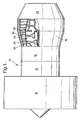
- a gas turbine engine 10 as shown in figure 1 comprises in flow series a fan 12, a compressor 14, a combustion system 16, a turbine section 18, and a nozzle 20.
- the turbine section 18 comprises a number of rotors 22 and stator vanes 26, each rotor 22 has a number of turbine blades 24 which extend radially therefrom.
- Figures 2 and 3 illustrate the leakage of hot air or gas over the tip of the aerofoil portions 30.
- the aerofoil 30 has a leading edge 32 and a trailing edge 34.
- a portion of the flow of gas migrates from the concave pressure surface 36 to the convex suction surface 38 over the tip of the aerofoil portion of the blade 24.
- This leakage flow exists because of a pressure difference between the pressure and suction surfaces 36,38.
- the flow over the tip of the aerofoil forms a vortex indicated by arrow A.
- FIGs 4 to 6 show the tip of an aerofoil section incorporating the gutter.
- the aerofoil section is indicated by line C.
- a gutter 40 is positioned over the tip of the aerofoil. It is envisaged that the gutter 40 may comprise two walls unconnected at the trailing edge and the leading edge (not shown).
- the gutter 40 provides a passage 42 defined by a peripheral wall 44 .
- An exit 46 is provided in the wall 44 at the trailing edge 34 of the aerofoil.
- the direction of leakage flow across the tip of the aerofoil is shown by the arrow D.
- the turbine casing 48 is in close proximity to the gutter 40 and overtip leakage flow is directed into the gutter in the direction of arrow E.
- the gutter 40 is in close proximity to the turbine casing 48 and the flow is directed between the casing and into the gutter 40 in the direction of arrow C and to the exit aperture 46.
- the exit aperture is at its widest at the 'trailing edge' of the gutter.
- Fuel is burnt with the compressed air in the combustion system 16, and hot gases produced by combustion of the fuel and the air flow through the turbine section 18 and the nozzle 20 to atmosphere.
- the hot gases drive the turbines which in turn drive the fan 12 and compressors 14 via shafts.
- the turbine section 18 comprises stator vanes 26 and rotor blades 24 arranged alternately, each stator vane 26 directs the hot gases onto the aerofoil 30 of the rotor blade 24 at an optimum angle. Each rotor blade 24 takes kinetic energy from the hot gases as they flow through the turbine section 18 in order to drive the fan 12 and the compressor 14.
- the efficiency with which the rotor blades 24 take kinetic energy from hot gases determines the efficiency of the turbine and this is partially dependent upon the leakage flow of hot gases between tip of the aerofoil 30 and the turbine casing 48.
- the leakage flow across the tip of the aerofoil 30 is trapped within the passage formed by the gutter 40 positioned over the aerofoil tip. In the embodiment as indicated in Figure 5 this trapped flow forms a vortex A within the gutter. The flow is then redirected along the passage subsequently exhausting from the gutter trailing edge through the exit aperture 46.
- the exit aperture 46 comprises an area or width large enough to allow all the flow that occurs between the casing 48 and the pressure side portion of the gutter peripheral wall 44, to exit downstream.
- the exit aperture 46 Since the area of the exit aperture 46 is of a size sufficient to allow all the tip leakage flow (D) pass through it (as a vortex A), this reduces the risk of some tip leakage flow continuing to exit over the suction side portion 50 of the gutter peripheral wall 44 into the main passage, as is the case for a rotor with a plain rotor tip.
- the overtip leakage flow D again forms a vortex A within the gutter 40
- the gutter is large enough such that the passage vortex B also forms in the gutter itself.
- the passage vortex B is formed from the casing boundary layer flow which, in this embodiment, passes between the casing 48 and the suction side portion 50 of the gutter peripheral wall 44.
- the area of the exit aperture is of a width sufficient to allow both vortex flows A and B to pass through it.
- the exit aperture is of a size sufficient to allow both flows A and B to pass through it.
- the target velocity distribution of the flow in close proximity to the gutter 40 is for the flow to accelerate continuously to the trailing edge on both the pressure and suction surface sides and thus obtain the peak Mach number(minimum static pressure) at the trailing edge.
- the aim is for the static pressure in the gutter 40 to match that on the external suction surface 38 of the aerofoil, this will help prevent flow trapped within the gutter from flowing over the sides of the gutter.
- a vortex may form within the passage formed by the gutter 40.
- the vortex may be weaker than that formed if the overtip leakage flow had been allowed to penetrate the main flow. Interaction of the vortex formed within the gutter 40 will be prevented until the flow is exhausted from the gutter trailing edge.
- the flow F along the gutter 40 is established near the leading edge 32 and flows to the trailing edge 34.
- the flow already established in the gutter may act to reduce flow over the peripheral wall 44, nearer to the trailing edge 34 ie. act as an ever increasing cross-flow to later leakage flow.
- the gutter 40 is as effective near the trailing edge as it is further upstream.
Landscapes
- Engineering & Computer Science (AREA)
- Mechanical Engineering (AREA)
- General Engineering & Computer Science (AREA)
- Turbine Rotor Nozzle Sealing (AREA)
Claims (2)
- Turbinenlaufschaufel (24) ohne Schaufelringsegment mit einem Schaufelprofil (30), das eine Vorderkante (32) und eine Hinterkante (34) aufweist, wobei das radial äußere Ende des Schaufelprofils einen durch die Umfangswand (44, 50) einer Rinne (40) definierten Kanal (42) aufweist, der sich von der Vorderkante (32) nach der Hinterkante (34) erstreckt und wobei eine Öffnung (46) in der Wand (44, 50) in der Nähe der Hinterkante (34) des Schaufelprofils (30) ausgebildet ist,
dadurch gekennzeichnet, daß an jeder Stelle der Mehrzahl von Stellen zwischen der Vorderkante (32) und der Hinterkante (34) der Rotorschaufel (24) in einer Ebene normal zur radialen Erstreckung der Rotorschaufel (24) die Breite des Kanals (42) größer ist als die Breite des radial äußeren Schaufelprofilabschnitts (30) benachbart hierzu. - Turbinenlaufschaufel (24) nach Anspruch 1,
dadurch gekennzeichnet, daß die Breite des Kanals (42) von der Vorderkante (32) der Laufschaufel (24) nach ihrer Hinterkante (34) progressiv breiter wird als die Breite des radial äußeren Schaufelprofils (30) benachbart hierzu.
Applications Claiming Priority (2)
| Application Number | Priority Date | Filing Date | Title |
|---|---|---|---|
| GB9607578 | 1996-04-12 | ||
| GBGB9607578.3A GB9607578D0 (en) | 1996-04-12 | 1996-04-12 | Turbine rotor blades |
Publications (3)
| Publication Number | Publication Date |
|---|---|
| EP0801209A2 EP0801209A2 (de) | 1997-10-15 |
| EP0801209A3 EP0801209A3 (de) | 1999-07-07 |
| EP0801209B1 true EP0801209B1 (de) | 2003-01-08 |
Family
ID=10791934
Family Applications (1)
| Application Number | Title | Priority Date | Filing Date |
|---|---|---|---|
| EP97301854A Expired - Lifetime EP0801209B1 (de) | 1996-04-12 | 1997-03-19 | Spitzendichtung für Turbinenlaufschaufeln |
Country Status (4)
| Country | Link |
|---|---|
| US (1) | US6142739A (de) |
| EP (1) | EP0801209B1 (de) |
| DE (1) | DE69718229T2 (de) |
| GB (1) | GB9607578D0 (de) |
Cited By (1)
| Publication number | Priority date | Publication date | Assignee | Title |
|---|---|---|---|---|
| EP1541806A2 (de) | 2003-12-11 | 2005-06-15 | ROLLS-ROYCE plc | Verbesserte Blattspitzendichtung einer Turbinenrotorschaufel |
Families Citing this family (36)
| Publication number | Priority date | Publication date | Assignee | Title |
|---|---|---|---|---|
| US20040101410A1 (en) * | 2001-10-02 | 2004-05-27 | Oleg Naljotov | Axial flow fluid machine |
| US6632069B1 (en) * | 2001-10-02 | 2003-10-14 | Oleg Naljotov | Step of pressure of the steam and gas turbine with universal belt |
| CN100386502C (zh) * | 2003-04-18 | 2008-05-07 | 奥莱格·耐尔卓托夫 | 具有改进的罩或密封件的蒸汽/气体涡轮机 |
| DE10352253A1 (de) * | 2003-11-08 | 2005-06-09 | Alstom Technology Ltd | Verdichterlaufschaufel |
| GB2413160B (en) | 2004-04-17 | 2006-08-09 | Rolls Royce Plc | Turbine rotor blades |
| GB0503185D0 (en) * | 2005-02-16 | 2005-03-23 | Rolls Royce Plc | A turbine blade |
| KR100758725B1 (ko) | 2005-10-17 | 2007-09-14 | 올레지 날조토브 | 유니버설 쉬라우드를 구비한 증기/가스 터빈 압력 단 |
| CA2675151A1 (en) * | 2006-01-13 | 2007-07-19 | Eth Zurich | Turbine blade with recessed tip |
| US20100136258A1 (en) * | 2007-04-25 | 2010-06-03 | Strock Christopher W | Method for improved ceramic coating |
| JP2009008014A (ja) * | 2007-06-28 | 2009-01-15 | Mitsubishi Electric Corp | 軸流ファン |
| US8262348B2 (en) * | 2008-04-08 | 2012-09-11 | Siemens Energy, Inc. | Turbine blade tip gap reduction system |
| FR2934008B1 (fr) * | 2008-07-21 | 2015-06-05 | Turbomeca | Aube creuse de roue de turbine comportant une nervure |
| GB0813556D0 (en) | 2008-07-24 | 2008-09-03 | Rolls Royce Plc | A blade for a rotor |
| GB201006450D0 (en) | 2010-04-19 | 2010-06-02 | Rolls Royce Plc | Blades |
| GB201006449D0 (en) | 2010-04-19 | 2010-06-02 | Rolls Royce Plc | Blades |
| US10294795B2 (en) * | 2010-04-28 | 2019-05-21 | United Technologies Corporation | High pitch-to-chord turbine airfoils |
| US10087764B2 (en) * | 2012-03-08 | 2018-10-02 | Pratt & Whitney Canada Corp. | Airfoil for gas turbine engine |
| US8926289B2 (en) | 2012-03-08 | 2015-01-06 | Hamilton Sundstrand Corporation | Blade pocket design |
| US9593584B2 (en) | 2012-10-26 | 2017-03-14 | Rolls-Royce Plc | Turbine rotor blade of a gas turbine |
| DE102012021400A1 (de) | 2012-10-31 | 2014-04-30 | Rolls-Royce Deutschland Ltd & Co Kg | Turbinenrotorschaufel einer Gasturbine |
| US9797258B2 (en) | 2013-10-23 | 2017-10-24 | General Electric Company | Turbine bucket including cooling passage with turn |
| US9638041B2 (en) | 2013-10-23 | 2017-05-02 | General Electric Company | Turbine bucket having non-axisymmetric base contour |
| US9528379B2 (en) | 2013-10-23 | 2016-12-27 | General Electric Company | Turbine bucket having serpentine core |
| US9347320B2 (en) | 2013-10-23 | 2016-05-24 | General Electric Company | Turbine bucket profile yielding improved throat |
| US9551226B2 (en) | 2013-10-23 | 2017-01-24 | General Electric Company | Turbine bucket with endwall contour and airfoil profile |
| US10352180B2 (en) | 2013-10-23 | 2019-07-16 | General Electric Company | Gas turbine nozzle trailing edge fillet |
| US9376927B2 (en) | 2013-10-23 | 2016-06-28 | General Electric Company | Turbine nozzle having non-axisymmetric endwall contour (EWC) |
| US9670784B2 (en) | 2013-10-23 | 2017-06-06 | General Electric Company | Turbine bucket base having serpentine cooling passage with leading edge cooling |
| US11448123B2 (en) * | 2014-06-13 | 2022-09-20 | Raytheon Technologies Corporation | Geared turbofan architecture |
| EP2977548B1 (de) * | 2014-07-22 | 2021-03-10 | Safran Aero Boosters SA | Schaufel und zugehörige strömungsmaschine |
| EP2987956A1 (de) * | 2014-08-18 | 2016-02-24 | Siemens Aktiengesellschaft | Verdichterschaufel |
| US10107108B2 (en) * | 2015-04-29 | 2018-10-23 | General Electric Company | Rotor blade having a flared tip |
| US10253637B2 (en) | 2015-12-11 | 2019-04-09 | General Electric Company | Method and system for improving turbine blade performance |
| US10808539B2 (en) | 2016-07-25 | 2020-10-20 | Raytheon Technologies Corporation | Rotor blade for a gas turbine engine |
| CN112282855B (zh) * | 2020-09-27 | 2022-08-16 | 哈尔滨工业大学 | 涡轮叶片 |
| US11608746B2 (en) * | 2021-01-13 | 2023-03-21 | General Electric Company | Airfoils for gas turbine engines |
Family Cites Families (24)
| Publication number | Priority date | Publication date | Assignee | Title |
|---|---|---|---|---|
| GB536238A (en) * | 1939-11-06 | 1941-05-07 | Fritz Albert Max Heppner | Improvements in and relating to internal combustion turbine plants |
| GB733918A (en) * | 1951-12-21 | 1955-07-20 | Power Jets Res & Dev Ltd | Improvements in blades of elastic fluid turbines and dynamic compressors |
| US2963268A (en) * | 1957-03-25 | 1960-12-06 | Gen Electric | Pressurized seal |
| DE1428165A1 (de) * | 1962-12-18 | 1969-02-20 | Licentia Gmbh | Verfahren zum Herstellen eines Endes einer Stroemungsmaschinenschaufel |
| US3635585A (en) * | 1969-12-23 | 1972-01-18 | Westinghouse Electric Corp | Gas-cooled turbine blade |
| BE794194A (fr) * | 1972-01-18 | 1973-07-18 | Bbc Sulzer Turbomaschinen | Aube mobile refroidie pour des turbines a gaz |
| GB1426049A (en) * | 1972-10-21 | 1976-02-25 | Rolls Royce | Rotor blade for a gas turbine engine |
| GB2005775B (en) * | 1977-10-08 | 1982-05-06 | Rolls Royce | Cooled rotor blade for a gas turbine engine |
| US4519745A (en) * | 1980-09-19 | 1985-05-28 | Rockwell International Corporation | Rotor blade and stator vane using ceramic shell |
| US4424001A (en) * | 1981-12-04 | 1984-01-03 | Westinghouse Electric Corp. | Tip structure for cooled turbine rotor blade |
| DE3217085A1 (de) * | 1982-05-07 | 1983-11-10 | Maschinenfabrik Korfmann Gmbh, 5810 Witten | Ventilatorfluegel an einem ventilator |
| US4526512A (en) * | 1983-03-28 | 1985-07-02 | General Electric Co. | Cooling flow control device for turbine blades |
| GB2155558A (en) * | 1984-03-10 | 1985-09-25 | Rolls Royce | Turbomachinery rotor blades |
| DE3500692A1 (de) * | 1985-01-11 | 1986-07-17 | MTU Motoren- und Turbinen-Union München GmbH, 8000 München | Axial- oder radiallaufschaufelgitter mit einrichtungen zur konstanthaltung des schaufelspitzenspiels |
| GB2279705B (en) * | 1985-07-24 | 1995-06-28 | Rolls Royce Plc | Cooling of turbine blades for a gas turbine engine |
| US4704587A (en) * | 1986-12-04 | 1987-11-03 | Western Digital Corporation | Crystal oscillator circuit for fast reliable start-up |
| US4761116A (en) * | 1987-05-11 | 1988-08-02 | General Electric Company | Turbine blade with tip vent |
| FR2623569A1 (fr) * | 1987-11-19 | 1989-05-26 | Snecma | Aube de compresseur a lechettes d'extremite dissymetriques |
| US4893987A (en) * | 1987-12-08 | 1990-01-16 | General Electric Company | Diffusion-cooled blade tip cap |
| US4896122A (en) * | 1989-07-14 | 1990-01-23 | Motorola, Inc. | Multiple bandwidth crystal controlled oscillator |
| US5331296A (en) * | 1992-10-16 | 1994-07-19 | National Semiconductor Corporation | Oscillator having controllable frequency compensation for suppressing undesired frequency of oscillation |
| US5688107A (en) * | 1992-12-28 | 1997-11-18 | United Technologies Corp. | Turbine blade passive clearance control |
| JP3137527B2 (ja) * | 1994-04-21 | 2001-02-26 | 三菱重工業株式会社 | ガスタービン動翼チップ冷却装置 |
| US5503527A (en) * | 1994-12-19 | 1996-04-02 | General Electric Company | Turbine blade having tip slot |
-
1996
- 1996-04-12 GB GBGB9607578.3A patent/GB9607578D0/en active Pending
-
1997
- 1997-03-19 EP EP97301854A patent/EP0801209B1/de not_active Expired - Lifetime
- 1997-03-19 DE DE69718229T patent/DE69718229T2/de not_active Expired - Lifetime
- 1997-03-25 US US08/824,206 patent/US6142739A/en not_active Expired - Lifetime
Cited By (1)
| Publication number | Priority date | Publication date | Assignee | Title |
|---|---|---|---|---|
| EP1541806A2 (de) | 2003-12-11 | 2005-06-15 | ROLLS-ROYCE plc | Verbesserte Blattspitzendichtung einer Turbinenrotorschaufel |
Also Published As
| Publication number | Publication date |
|---|---|
| US6142739A (en) | 2000-11-07 |
| EP0801209A3 (de) | 1999-07-07 |
| DE69718229T2 (de) | 2003-08-07 |
| DE69718229D1 (de) | 2003-02-13 |
| GB9607578D0 (en) | 1996-06-12 |
| EP0801209A2 (de) | 1997-10-15 |
Similar Documents
| Publication | Publication Date | Title |
|---|---|---|
| EP0801209B1 (de) | Spitzendichtung für Turbinenlaufschaufeln | |
| EP1541806B1 (de) | Verbesserte Blattspitzendichtung einer Turbinenrotorschaufel | |
| EP0792410B1 (de) | Rotorschaufeln zur verminderung von spaltverlusten | |
| US4948338A (en) | Turbine blade with cooled shroud abutment surface | |
| EP2450532B1 (de) | Rotorschaufeln | |
| JP5289694B2 (ja) | 翼端棚を有するタービンエーロフォイル湾曲スクイーラ翼端 | |
| US5238364A (en) | Shroud ring for an axial flow turbine | |
| CN101131097B (zh) | 叶片顶部级联挡板翼型 | |
| US5290144A (en) | Shroud ring for an axial flow turbine | |
| US8439643B2 (en) | Biformal platform turbine blade | |
| EP1793086B1 (de) | Gasturbinenschaufel mit einem Partikeldeflektor | |
| US8721291B2 (en) | Flow directing member for gas turbine engine | |
| CA2548893C (en) | Blade and disk radial pre-swirlers | |
| JP4152184B2 (ja) | 下降段を有するタービンのプラットフォーム | |
| US8967973B2 (en) | Turbine bucket platform shaping for gas temperature control and related method | |
| CN107084004B (zh) | 用于涡轮发动机部件的冲击孔 | |
| GB2155558A (en) | Turbomachinery rotor blades | |
| JPS63212704A (ja) | ターボ流体機械のエーロフォイル | |
| JPH09511304A (ja) | 曲折した冷却用チャネルを備えたタービンシュラウドセグメント | |
| CN101858230A (zh) | 关于用于涡轮发动机的密封部的方法、系统和/或装置 | |
| EP1693552A2 (de) | Turbinenschaufel | |
| EP3839218B1 (de) | Verbesserte rotorschaufeldichtungsstrukturen | |
| GB2110767A (en) | A shrouded rotor for a gas turbine engine | |
| CN117988935A (zh) | 具有流动表面的翼型件组件 | |
| EP0278434A2 (de) | Rotorblatt |
Legal Events
| Date | Code | Title | Description |
|---|---|---|---|
| PUAI | Public reference made under article 153(3) epc to a published international application that has entered the european phase |
Free format text: ORIGINAL CODE: 0009012 |
|
| AK | Designated contracting states |
Kind code of ref document: A2 Designated state(s): DE FR GB |
|
| PUAL | Search report despatched |
Free format text: ORIGINAL CODE: 0009013 |
|
| AK | Designated contracting states |
Kind code of ref document: A3 Designated state(s): DE FR GB |
|
| RIC1 | Information provided on ipc code assigned before grant |
Free format text: 6F 01D 5/20 A, 6F 01D 5/14 B |
|
| 17P | Request for examination filed |
Effective date: 19990621 |
|
| 17Q | First examination report despatched |
Effective date: 20010710 |
|
| GRAH | Despatch of communication of intention to grant a patent |
Free format text: ORIGINAL CODE: EPIDOS IGRA |
|
| GRAH | Despatch of communication of intention to grant a patent |
Free format text: ORIGINAL CODE: EPIDOS IGRA |
|
| GRAA | (expected) grant |
Free format text: ORIGINAL CODE: 0009210 |
|
| AK | Designated contracting states |
Kind code of ref document: B1 Designated state(s): DE FR GB |
|
| REG | Reference to a national code |
Ref country code: GB Ref legal event code: FG4D |
|
| REF | Corresponds to: |
Ref document number: 69718229 Country of ref document: DE Date of ref document: 20030213 Kind code of ref document: P |
|
| ET | Fr: translation filed | ||
| PLBE | No opposition filed within time limit |
Free format text: ORIGINAL CODE: 0009261 |
|
| STAA | Information on the status of an ep patent application or granted ep patent |
Free format text: STATUS: NO OPPOSITION FILED WITHIN TIME LIMIT |
|
| 26N | No opposition filed |
Effective date: 20031009 |
|
| REG | Reference to a national code |
Ref country code: FR Ref legal event code: PLFP Year of fee payment: 19 |
|
| REG | Reference to a national code |
Ref country code: FR Ref legal event code: PLFP Year of fee payment: 20 |
|
| PGFP | Annual fee paid to national office [announced via postgrant information from national office to epo] |
Ref country code: GB Payment date: 20160329 Year of fee payment: 20 Ref country code: FR Payment date: 20160328 Year of fee payment: 20 |
|
| PGFP | Annual fee paid to national office [announced via postgrant information from national office to epo] |
Ref country code: DE Payment date: 20160331 Year of fee payment: 20 |
|
| REG | Reference to a national code |
Ref country code: DE Ref legal event code: R071 Ref document number: 69718229 Country of ref document: DE |
|
| REG | Reference to a national code |
Ref country code: GB Ref legal event code: PE20 Expiry date: 20170318 |
|
| PG25 | Lapsed in a contracting state [announced via postgrant information from national office to epo] |
Ref country code: GB Free format text: LAPSE BECAUSE OF EXPIRATION OF PROTECTION Effective date: 20170318 |