EP0801243A2 - Accouplement hydrodynamique - Google Patents
Accouplement hydrodynamique Download PDFInfo
- Publication number
- EP0801243A2 EP0801243A2 EP97105665A EP97105665A EP0801243A2 EP 0801243 A2 EP0801243 A2 EP 0801243A2 EP 97105665 A EP97105665 A EP 97105665A EP 97105665 A EP97105665 A EP 97105665A EP 0801243 A2 EP0801243 A2 EP 0801243A2
- Authority
- EP
- European Patent Office
- Prior art keywords
- storage chamber
- housing
- working medium
- working
- coupling according
- Prior art date
- Legal status (The legal status is an assumption and is not a legal conclusion. Google has not performed a legal analysis and makes no representation as to the accuracy of the status listed.)
- Granted
Links
Images


Classifications
-
- F—MECHANICAL ENGINEERING; LIGHTING; HEATING; WEAPONS; BLASTING
- F16—ENGINEERING ELEMENTS AND UNITS; GENERAL MEASURES FOR PRODUCING AND MAINTAINING EFFECTIVE FUNCTIONING OF MACHINES OR INSTALLATIONS; THERMAL INSULATION IN GENERAL
- F16D—COUPLINGS FOR TRANSMITTING ROTATION; CLUTCHES; BRAKES
- F16D33/00—Rotary fluid couplings or clutches of the hydrokinetic type
- F16D33/06—Rotary fluid couplings or clutches of the hydrokinetic type controlled by changing the amount of liquid in the working circuit
- F16D33/08—Rotary fluid couplings or clutches of the hydrokinetic type controlled by changing the amount of liquid in the working circuit by devices incorporated in the fluid coupling, with or without remote control
- F16D33/10—Rotary fluid couplings or clutches of the hydrokinetic type controlled by changing the amount of liquid in the working circuit by devices incorporated in the fluid coupling, with or without remote control consisting of controllable supply and discharge openings
Definitions
- the invention relates to a hydrodynamic coupling with a pump wheel and a turbine wheel, which form a toroidal working space with one another and which have a storage chamber.
- Hydrodynamic couplings with constant filling are generally used as start-up and overload clutches.
- the transmittable torque for a given slip is determined by the amount of oil filled and the drive speed.
- the starting torque can be reduced, for example, by a deceleration chamber.
- Working space and delay chamber are connected to each other via nozzles.
- working medium gets more or less quickly out of the delay chamber into the working area. In this way, the increase in torque over time can be influenced.
- This type of coupling offers the advantage of heat dissipation over the surface, since the parts surrounding the circuit rotate in air and can be optimized for cooling by suitable shaping.
- the invention has for its object to design a hydrodynamic coupling of the type defined in such a way that it fulfills its functions perfectly with little structural effort and low manufacturing costs, that the degree of filling of the work space can be controlled quickly and reliably, and that no external oil supply system is necessary .
- the transmissible torque of the clutch should be able to be changed arbitrarily during operation.
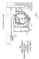
- Figure 1 shows a hydrodynamic coupling in an axial section.
- a pump wheel 1 and a turbine wheel 2 together form a toroidal working space.
- An inner housing 3 encloses part of the turbine wheel 2 with a trough-shaped wall 3.1.
- a first storage space 3.2 is provided at the radially inner end of the wall part 3.1. This is limited by an annular disc 3.3 against the turbine wheel.
- the inner housing also has a wall part 3.4. This is bulged so that it has the shape of an annular trough.
- a storage chamber 3.5 can also be seen. This is formed from a further wall part 3.6 and a partition 3.7. At the radially outer end of the partition 3.7 there is a bore 3.8. This creates a conductive connection between the tub and the storage chamber 3.5.
- a dynamic pressure pump 5 This has the shape of a pipe socket. At the radially outer end there is a mouthpiece 5.1. In the present case, the pipe socket runs perpendicular to the machine axis. He
- the dynamic pressure pump 5 is at its radially inner end in a conductive connection with the working space, which is formed from the pump wheel 1 and the turbine wheel 2. This is illustrated by the strongly drawn arrow. In this case, the conductive connection is established by a corresponding position of a rotary valve 6. Of course, any other type of valve could also be used.
- the housing 3 is surrounded by an outer housing 7.
- the entire hydrodynamic coupling is designed such that it can be connected to a drive motor 8 by being plugged on. From this one can see a housing 8.1 and a flywheel 8.2, to which an annular driver 8.3 is screwed.
- a plurality of driver claws 3.9 are formed on wall part 3.1.
- the outer housing 7 has special ventilation.
- an air inlet 9 between the motor 8 and the turbine wheel 2. This is formed from two annular disks 9.1 and 9.2, which form an annular, radial inlet channel.
- the inlet duct is connected to the outside environment through a plurality of bores, not shown, so that air can enter from the outside.
- the air flows around the radially inner edge of the annular disk 9.2, along the wall part 3.1, on which the air scoops are formed, and then exits the outer housing 7 through bores 9.3 to 9.7.
- Intensive cooling of the internal components of the hydrodynamic coupling takes place, namely by sweeping the cold air past the surface of the housing 3.
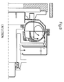
- FIGS. 4 to 9 illustrate further important embodiments of couplings according to the invention in a schematic representation.
- the essential parts of the coupling can also be seen here, namely the pump wheel 1, the turbine wheel 2, the dynamic pressure pump 5, the working chamber 21 and the pump chamber 22.
- the pump chamber 22 is here dimensioned such that the filling in the working space 21 is greatly reduced in the start-up state.
- the oil in the pump chamber 22 is skimmed off by the dynamic pressure pump 5 and fed to the working chamber 21 radially on the inside.
- the pump wheel 1 has nozzle bores 23, 24, via which a conductive connection between the working chamber 21 and the pump chamber 22 is established. By adjusting the nozzle bores accordingly and adjusting the valve accordingly (not shown here), the chronological course of the increase in torque can be determined until the working space 21 is completely filled.
- an additional storage space 25 is provided. This is delimited against the pump chamber 22 by a partition 3.7. Pump chamber 22 and additional storage chamber 25 are in conductive connection with one another via nozzle bores 26.
- the valve (not shown) in the pitot tube can optionally be switched such that the oil flows from the pump chamber 22 to the work chamber or to the additional storage space.
- the transferable torque of the clutch can be reduced - apart from the air ventilation torque - by suitable adjustment of the nozzle bores and the valve cross-section.
- a further storage space 1.1 is formed, which also serves to delay the start-up and thus to make it gentle.
- Motor 8 drives the flywheel 8.2. This takes the driver 8.3. From there, a torque is transmitted to the driving claws 3.9, and thus to the pump wheel 1. From the pump wheel 1, the torque is transmitted hydrodynamically to the turbine wheel 2, and from there to a shaft 10 and a V-belt pulley 11.
- the hydrodynamic coupling according to the invention works completely independently, that is, without an external oil supply system.
- the receiving volume of the storage chamber 3.5 is dimensioned according to the volume of the work area.
- the valve can be switched as desired from the outside, on the one hand in the two extreme positions, which are shown here, in order to establish a conductive connection between the dynamic pressure pump either with the working space or with the storage chamber 3.5.
- the valve 6 can also be set in intermediate positions, so that very different operating behaviors can be generated.
- Storage space 3.2 is in a conductive connection with the working space via an annular gap 12 between the turbine wheel 2 and the wall part 3.1. Since this is the only conductive connection between the storage space 3.2 and the work space, cooling of the work space after the standstill takes place is greatly delayed via the annular gap 12.
- the temperature of the working medium itself is measured.
- it is an oil. This means that a sensor is placed in the oil flow.
Landscapes
- Engineering & Computer Science (AREA)
- General Engineering & Computer Science (AREA)
- Mechanical Engineering (AREA)
- Catching Or Destruction (AREA)
- Supercharger (AREA)
- Hydraulic Clutches, Magnetic Clutches, Fluid Clutches, And Fluid Joints (AREA)
- Control Of Turbines (AREA)
- Structures Of Non-Positive Displacement Pumps (AREA)
Applications Claiming Priority (2)
| Application Number | Priority Date | Filing Date | Title |
|---|---|---|---|
| DE19614589A DE19614589A1 (de) | 1996-04-12 | 1996-04-12 | Hydrodynamische Kupplung |
| DE19614589 | 1996-04-12 |
Publications (3)
| Publication Number | Publication Date |
|---|---|
| EP0801243A2 true EP0801243A2 (fr) | 1997-10-15 |
| EP0801243A3 EP0801243A3 (fr) | 1998-07-01 |
| EP0801243B1 EP0801243B1 (fr) | 2002-07-17 |
Family
ID=7791151
Family Applications (1)
| Application Number | Title | Priority Date | Filing Date |
|---|---|---|---|
| EP97105665A Expired - Lifetime EP0801243B1 (fr) | 1996-04-12 | 1997-04-05 | Accouplement hydrodynamique |
Country Status (3)
| Country | Link |
|---|---|
| US (1) | US6101810A (fr) |
| EP (1) | EP0801243B1 (fr) |
| DE (2) | DE19614589A1 (fr) |
Cited By (4)
| Publication number | Priority date | Publication date | Assignee | Title |
|---|---|---|---|---|
| CN1331713C (zh) * | 2003-12-23 | 2007-08-15 | 沃易斯涡轮股份有限公司 | 具有热熔断器功能的封闭件及其制造方法 |
| US7716925B2 (en) | 2003-12-23 | 2010-05-18 | Voith Turbo Gmbh & Co. | Closure with a thermal safeguard function |
| EP2479448A1 (fr) * | 2011-01-18 | 2012-07-25 | Siemens Aktiengesellschaft | Embrayage hydrodynamique doté d'une préchambre à plusieurs niveaux |
| WO2018224428A1 (fr) * | 2017-06-08 | 2018-12-13 | Voith Patent Gmbh | Embrayage hydrodynamique |
Families Citing this family (13)
| Publication number | Priority date | Publication date | Assignee | Title |
|---|---|---|---|---|
| DE19802524B4 (de) | 1998-01-26 | 2005-12-22 | Voith Turbo Gmbh & Co. Kg | Hydrodynamische Kupplung |
| DE19902296A1 (de) * | 1999-01-21 | 2000-08-17 | Voith Turbo Kg | Hydrodynamische Kupplung |
| DE102004006358B4 (de) * | 2004-02-09 | 2012-11-15 | Voith Turbo Gmbh & Co. Kg | Themperaturüberwachte hydrodynamische Maschine |
| DE102004059833A1 (de) * | 2004-12-10 | 2006-06-14 | Voith Turbo Gmbh & Co. Kg | Verfahren zum Regeln der maximalen Drehzahl einer Arbeitsmaschine und hydrodynamische Kupplung hierfür |
| DE102005004524B3 (de) | 2005-01-31 | 2006-05-18 | Voith Turbo Gmbh & Co. Kg | Hydrodynamische Maschine, zum Beispiel hydrodynamische Kupplung oder hydrodynamische Bremse |
| DE102007005429B4 (de) * | 2007-01-30 | 2009-06-25 | Voith Patent Gmbh | Hydrodynamische Maschine |
| KR100885549B1 (ko) | 2007-06-14 | 2009-02-26 | 최쌍석 | 물을 작동매체로 사용하는 가변속 구동장치 |
| DE102007056495A1 (de) * | 2007-11-22 | 2009-04-23 | Voith Patent Gmbh | Hydrodynamische Kupplung |
| DE102008007046A1 (de) | 2008-01-31 | 2009-08-06 | Voith Patent Gmbh | Verfahren zur Steuerung der Leistungsübertragung einer hydrodynamischen Maschine in einem Antriebsstrang und Antriebsstrang |
| US20110054240A1 (en) * | 2009-09-03 | 2011-03-03 | Bender Eddie L | Induced Relaxation And Therapeutic Apparatus And Method |
| RU2523338C2 (ru) * | 2012-01-27 | 2014-07-20 | Общество с ограниченной ответственностью "Конструкторское технологическое бюро "Техно-прогресс" | Муфта гидродинамическая регулируемая изменением наполнения |
| DE102013219180A1 (de) * | 2013-09-24 | 2015-03-26 | Voith Patent Gmbh | Verfahren zum Betreiben eines Antriebsstrangs mit einer hydrodynamischen Kupplung |
| CN121301892A (zh) * | 2025-12-04 | 2026-01-09 | 北京建筑大学 | 基于钻孔进度监测的气动冲击不同破坏模式的确定方法 |
Family Cites Families (31)
| Publication number | Priority date | Publication date | Assignee | Title |
|---|---|---|---|---|
| US29928A (en) * | 1860-09-04 | Improvement in presses | ||
| DE7024735U (de) * | Fabbrica Automobili Isotta Fraschini E Motori Breda Spa | Strömungskupplung und Getriebe | ||
| US1859607A (en) * | 1928-10-17 | 1932-05-24 | Sinclair Harold | Hydraulic transmission gear and brake |
| US2202243A (en) * | 1938-06-09 | 1940-05-28 | American Blower Corp | Cooling ribs-scoop controlled coupling |
| DE883377C (de) * | 1939-04-30 | 1953-07-16 | Voith Gmbh J M | Auslasssteuerung fuer Stroemungskreislaeufe |
| DE874712C (de) * | 1940-02-17 | 1953-04-27 | Gen Motors Corp | Vorrichtung zum Kuehlen der zwischen dem Motor und dem UEbersetzungs-getriebe von Kraftfahrzeugen eingeschalteten Fluessigkeitskupplung nach Foettinger-Bauart |
| DE909272C (de) * | 1943-10-21 | 1954-04-15 | Voith Gmbh J M | Stroemungskupplung mit veraenderlichem Fuellungsgrad |
| DE867030C (de) * | 1943-11-23 | 1953-02-16 | Harold Sinclair | Stroemungskupplung oder durch Fliehkraft einer Fluessigkeit betaetigte Reibungskupplung |
| GB667565A (en) * | 1947-06-11 | 1952-03-05 | Ljungstroms Angturbin Ab | Improvements in the cooling of rotating bodies |
| GB747392A (en) * | 1951-02-28 | 1956-04-04 | Voith Gmbh J M | Improvements relating to hydraulic couplings |
| US3075354A (en) * | 1953-09-03 | 1963-01-29 | Sinclair Harold | Hydraulic turbo couplings |
| DE1037779B (de) * | 1954-09-25 | 1958-08-28 | Maschf Augsburg Nuernberg Ag | Fluessigkeitskupplung |
| DE1194207B (de) * | 1956-01-18 | 1965-06-03 | Harold Sinclair | Hydrodynamische Kupplung mit veraenderbarer Arbeitskammerfuellung |
| US2831323A (en) * | 1956-09-13 | 1958-04-22 | American Radiator & Standard | Scoop and jet pump fluid regulating means for fluid couplings |
| GB922415A (en) * | 1958-09-22 | 1963-04-03 | American Radiator & Standard | Improvements in or relating to fluid couplings |
| US3045430A (en) * | 1960-09-20 | 1962-07-24 | John E Becker | Fluid couplings |
| US3157999A (en) * | 1962-09-05 | 1964-11-24 | Liquid Drive Corp | Fluid coupling |
| GB1000565A (en) * | 1963-04-02 | 1965-08-04 | American Radiator & Standard | Improvements in or relating to fluid couplings |
| US3405524A (en) * | 1967-02-13 | 1968-10-15 | American Radiator & Standard | Liquid level sensing and control means for fluid drives |
| DE2035539A1 (de) * | 1970-07-17 | 1972-01-20 | Kopo Apparatebau GmbH, 5630 Remscheid | Behalter |
| US3751923A (en) * | 1972-02-11 | 1973-08-14 | Eclipse Consult | Valve controlled hydraulic coupling |
| US3952508A (en) | 1975-03-31 | 1976-04-27 | Eaton Corporation | Control for fluid coupling |
| DE2757252C2 (de) * | 1977-12-22 | 1983-08-04 | Voith-Turbo Gmbh & Co Kg, 7180 Crailsheim | Flüssigkeitskupplung |
| DE3047361A1 (de) * | 1980-12-16 | 1982-07-15 | Klöckner-Humboldt-Deutz AG, 5000 Köln | Kuehlluftgeblaese fuer eine luftgekuehlte brennkraftmaschine |
| IT1145067B (it) * | 1981-04-06 | 1986-11-05 | Valeriano Fiorentini | Giunto idraulico idrodinamico dotato di mezzi di controllo |
| CA1209440A (fr) * | 1982-06-22 | 1986-08-12 | John Elderton | Accouplement fluidique a aubes et contre-aubes |
| DE3240334C2 (de) * | 1982-10-30 | 1985-01-24 | Voith-Turbo Gmbh & Co Kg, 7180 Crailsheim | Hydrodynamische Kupplung |
| GB2156051B (en) * | 1984-02-03 | 1988-01-06 | Fluidrive Eng Co Ltd | Fluid couplings |
| DE3743292A1 (de) * | 1987-12-19 | 1989-06-29 | Porsche Ag | Kupplung |
| DE4224728C2 (de) * | 1992-07-27 | 1998-01-15 | Voith Turbo Kg | Hydrodynamische Kupplung |
| US5426939A (en) * | 1993-06-28 | 1995-06-27 | Cottrell; Harold L. | Torque converter having automatic power control |
-
1996
- 1996-04-12 DE DE19614589A patent/DE19614589A1/de not_active Withdrawn
-
1997
- 1997-04-05 EP EP97105665A patent/EP0801243B1/fr not_active Expired - Lifetime
- 1997-04-05 DE DE59707703T patent/DE59707703D1/de not_active Expired - Lifetime
- 1997-04-10 US US08/827,653 patent/US6101810A/en not_active Expired - Lifetime
Cited By (4)
| Publication number | Priority date | Publication date | Assignee | Title |
|---|---|---|---|---|
| CN1331713C (zh) * | 2003-12-23 | 2007-08-15 | 沃易斯涡轮股份有限公司 | 具有热熔断器功能的封闭件及其制造方法 |
| US7716925B2 (en) | 2003-12-23 | 2010-05-18 | Voith Turbo Gmbh & Co. | Closure with a thermal safeguard function |
| EP2479448A1 (fr) * | 2011-01-18 | 2012-07-25 | Siemens Aktiengesellschaft | Embrayage hydrodynamique doté d'une préchambre à plusieurs niveaux |
| WO2018224428A1 (fr) * | 2017-06-08 | 2018-12-13 | Voith Patent Gmbh | Embrayage hydrodynamique |
Also Published As
| Publication number | Publication date |
|---|---|
| EP0801243A3 (fr) | 1998-07-01 |
| DE19614589A1 (de) | 1997-10-16 |
| US6101810A (en) | 2000-08-15 |
| DE59707703D1 (de) | 2002-08-22 |
| EP0801243B1 (fr) | 2002-07-17 |
Similar Documents
| Publication | Publication Date | Title |
|---|---|---|
| EP0801243B1 (fr) | Accouplement hydrodynamique | |
| DE602004001102T2 (de) | Hydraulisch gesteuerter Propellerantrieb mit integrierter Kühlung | |
| DE102012219182B4 (de) | Verteilergetriebevorrichtung mit einer Differentialgetriebeeinrichtung | |
| DE1922508A1 (de) | Steuerung fuer ein automatisches Schaltgetriebe | |
| EP2640618B1 (fr) | Chaîne cinématique avec ralentisseur hydrodynamique et procédé de réglage le couple de freinage | |
| WO2006061221A1 (fr) | Procede pour reguler le regime maximal d'une machine et transmission hydrodynamique associee | |
| DE3240334C2 (de) | Hydrodynamische Kupplung | |
| DE69913452T2 (de) | Abgestufte Dichtung und Buchse | |
| DE3322779C2 (de) | Flüssigkeitsreibungskupplung | |
| DE4442451A1 (de) | Flüssigkeitsreibungskupplung | |
| DE102007026141A1 (de) | Drehmomentübertragungseinrichtung | |
| EP2464886B1 (fr) | Procédé de commande de l'apport en agent de refroidissement et de l'apport en lubrifiant à l'embrayage d'un véhicule à moteur comprenant une boîte de vitesses automatique | |
| DE3504001A1 (de) | Steuersystem fuer einen direktkupplungsmechanismus in einem direktkupplungsmechanismus einer hydraulischen kraftuebertragungseinrichtung eines fahrzeuggetriebes | |
| EP2861891B1 (fr) | Procédé et dispositif de thermorégulation d'un fluide de lubrification | |
| DE102016120889A1 (de) | Antriebsstrangkomponente mit Mechanismus zur Steuerung des Schmiermittelpegels | |
| EP2429869B1 (fr) | Procédé de transformation ou de fabrication d'une chaîne cinématique et ralentisseur hydrodynamique | |
| DE102011100801B4 (de) | Kupplungsgetriebe mit einem Pumpen-Elektromotor, der mechanisch mit einem Ventil wirkverbunden ist, um das Ventil in Abhängigkeit der Drehrichtung des Elektromotors zu betätigen, Verfahren zum Betreiben dieses Kupplungsgetriebes | |
| DE2504057A1 (de) | Vorrichtung zur hydrokinetischen drehmomentuebertragung | |
| DE3440428A1 (de) | Temperaturgesteuerter luefterantrieb fuer maschinen grosser leistung | |
| DE112014006717B4 (de) | Überbrückungskupplung für einen drehmomentwandler | |
| DE102006011987A1 (de) | Antriebsstrang mit einem Turboverbundsystem | |
| DE3104964C2 (fr) | ||
| EP0801242B1 (fr) | Accouplement hydrodynamique | |
| DE102018216243A1 (de) | Drehantriebseinheit für ein Gebläse | |
| EP1621786B1 (fr) | Propulsion pour véhicule, notamment pour motocyclette |
Legal Events
| Date | Code | Title | Description |
|---|---|---|---|
| PUAI | Public reference made under article 153(3) epc to a published international application that has entered the european phase |
Free format text: ORIGINAL CODE: 0009012 |
|
| AK | Designated contracting states |
Kind code of ref document: A2 Designated state(s): DE FR GB IT |
|
| PUAL | Search report despatched |
Free format text: ORIGINAL CODE: 0009013 |
|
| AK | Designated contracting states |
Kind code of ref document: A3 Designated state(s): DE FR GB IT |
|
| 17P | Request for examination filed |
Effective date: 19980714 |
|
| 17Q | First examination report despatched |
Effective date: 20001227 |
|
| GRAG | Despatch of communication of intention to grant |
Free format text: ORIGINAL CODE: EPIDOS AGRA |
|
| GRAG | Despatch of communication of intention to grant |
Free format text: ORIGINAL CODE: EPIDOS AGRA |
|
| GRAH | Despatch of communication of intention to grant a patent |
Free format text: ORIGINAL CODE: EPIDOS IGRA |
|
| GRAH | Despatch of communication of intention to grant a patent |
Free format text: ORIGINAL CODE: EPIDOS IGRA |
|
| GRAA | (expected) grant |
Free format text: ORIGINAL CODE: 0009210 |
|
| AK | Designated contracting states |
Kind code of ref document: B1 Designated state(s): DE FR GB IT |
|
| REG | Reference to a national code |
Ref country code: GB Ref legal event code: FG4D Free format text: NOT ENGLISH |
|
| GBT | Gb: translation of ep patent filed (gb section 77(6)(a)/1977) |
Effective date: 20020717 |
|
| REF | Corresponds to: |
Ref document number: 59707703 Country of ref document: DE Date of ref document: 20020822 |
|
| ET | Fr: translation filed | ||
| PLBE | No opposition filed within time limit |
Free format text: ORIGINAL CODE: 0009261 |
|
| STAA | Information on the status of an ep patent application or granted ep patent |
Free format text: STATUS: NO OPPOSITION FILED WITHIN TIME LIMIT |
|
| 26N | No opposition filed |
Effective date: 20030422 |
|
| PGFP | Annual fee paid to national office [announced via postgrant information from national office to epo] |
Ref country code: IT Payment date: 20130420 Year of fee payment: 17 |
|
| PG25 | Lapsed in a contracting state [announced via postgrant information from national office to epo] |
Ref country code: IT Free format text: LAPSE BECAUSE OF NON-PAYMENT OF DUE FEES Effective date: 20140405 |
|
| REG | Reference to a national code |
Ref country code: FR Ref legal event code: PLFP Year of fee payment: 19 |
|
| PGFP | Annual fee paid to national office [announced via postgrant information from national office to epo] |
Ref country code: GB Payment date: 20150420 Year of fee payment: 19 Ref country code: DE Payment date: 20150421 Year of fee payment: 19 |
|
| PGFP | Annual fee paid to national office [announced via postgrant information from national office to epo] |
Ref country code: FR Payment date: 20150421 Year of fee payment: 19 |
|
| REG | Reference to a national code |
Ref country code: DE Ref legal event code: R119 Ref document number: 59707703 Country of ref document: DE |
|
| GBPC | Gb: european patent ceased through non-payment of renewal fee |
Effective date: 20160405 |
|
| REG | Reference to a national code |
Ref country code: FR Ref legal event code: ST Effective date: 20161230 |
|
| PG25 | Lapsed in a contracting state [announced via postgrant information from national office to epo] |
Ref country code: FR Free format text: LAPSE BECAUSE OF NON-PAYMENT OF DUE FEES Effective date: 20160502 Ref country code: GB Free format text: LAPSE BECAUSE OF NON-PAYMENT OF DUE FEES Effective date: 20160405 Ref country code: DE Free format text: LAPSE BECAUSE OF NON-PAYMENT OF DUE FEES Effective date: 20161101 |