EP0801251B1 - Zweiteiliges Gehäuse für ein Verbundgetriebe - Google Patents
Zweiteiliges Gehäuse für ein Verbundgetriebe Download PDFInfo
- Publication number
- EP0801251B1 EP0801251B1 EP97105529A EP97105529A EP0801251B1 EP 0801251 B1 EP0801251 B1 EP 0801251B1 EP 97105529 A EP97105529 A EP 97105529A EP 97105529 A EP97105529 A EP 97105529A EP 0801251 B1 EP0801251 B1 EP 0801251B1
- Authority
- EP
- European Patent Office
- Prior art keywords
- transmission
- housing
- section
- main
- auxiliary
- Prior art date
- Legal status (The legal status is an assumption and is not a legal conclusion. Google has not performed a legal analysis and makes no representation as to the accuracy of the status listed.)
- Expired - Lifetime
Links
- 230000005540 biological transmission Effects 0.000 title claims description 117
- 150000001875 compounds Chemical class 0.000 title claims description 24
- 230000002441 reversible effect Effects 0.000 claims description 9
- 230000007246 mechanism Effects 0.000 claims description 6
- 230000008859 change Effects 0.000 claims description 2
- 230000000712 assembly Effects 0.000 description 5
- 238000000429 assembly Methods 0.000 description 5
- 238000005266 casting Methods 0.000 description 4
- 230000008878 coupling Effects 0.000 description 3
- 238000010168 coupling process Methods 0.000 description 3
- 238000005859 coupling reaction Methods 0.000 description 3
- 230000009467 reduction Effects 0.000 description 2
- 230000001360 synchronised effect Effects 0.000 description 2
- 230000004323 axial length Effects 0.000 description 1
- 230000009977 dual effect Effects 0.000 description 1
- 230000008030 elimination Effects 0.000 description 1
- 238000003379 elimination reaction Methods 0.000 description 1
- ZINJLDJMHCUBIP-UHFFFAOYSA-N ethametsulfuron-methyl Chemical compound CCOC1=NC(NC)=NC(NC(=O)NS(=O)(=O)C=2C(=CC=CC=2)C(=O)OC)=N1 ZINJLDJMHCUBIP-UHFFFAOYSA-N 0.000 description 1
- 230000008676 import Effects 0.000 description 1
- 238000003754 machining Methods 0.000 description 1
- 230000013011 mating Effects 0.000 description 1
- 238000004513 sizing Methods 0.000 description 1
Images


Classifications
-
- F—MECHANICAL ENGINEERING; LIGHTING; HEATING; WEAPONS; BLASTING
- F16—ENGINEERING ELEMENTS AND UNITS; GENERAL MEASURES FOR PRODUCING AND MAINTAINING EFFECTIVE FUNCTIONING OF MACHINES OR INSTALLATIONS; THERMAL INSULATION IN GENERAL
- F16H—GEARING
- F16H57/00—General details of gearing
- F16H57/02—Gearboxes; Mounting gearing therein
- F16H2057/02039—Gearboxes for particular applications
- F16H2057/02043—Gearboxes for particular applications for vehicle transmissions
-
- F—MECHANICAL ENGINEERING; LIGHTING; HEATING; WEAPONS; BLASTING
- F16—ENGINEERING ELEMENTS AND UNITS; GENERAL MEASURES FOR PRODUCING AND MAINTAINING EFFECTIVE FUNCTIONING OF MACHINES OR INSTALLATIONS; THERMAL INSULATION IN GENERAL
- F16H—GEARING
- F16H57/00—General details of gearing
- F16H57/02—Gearboxes; Mounting gearing therein
- F16H2057/02095—Measures for reducing number of parts or components
-
- Y—GENERAL TAGGING OF NEW TECHNOLOGICAL DEVELOPMENTS; GENERAL TAGGING OF CROSS-SECTIONAL TECHNOLOGIES SPANNING OVER SEVERAL SECTIONS OF THE IPC; TECHNICAL SUBJECTS COVERED BY FORMER USPC CROSS-REFERENCE ART COLLECTIONS [XRACs] AND DIGESTS
- Y10—TECHNICAL SUBJECTS COVERED BY FORMER USPC
- Y10T—TECHNICAL SUBJECTS COVERED BY FORMER US CLASSIFICATION
- Y10T74/00—Machine element or mechanism
- Y10T74/19—Gearing
- Y10T74/19167—In series plural interchangeably locked nonplanetary units
-
- Y—GENERAL TAGGING OF NEW TECHNOLOGICAL DEVELOPMENTS; GENERAL TAGGING OF CROSS-SECTIONAL TECHNOLOGIES SPANNING OVER SEVERAL SECTIONS OF THE IPC; TECHNICAL SUBJECTS COVERED BY FORMER USPC CROSS-REFERENCE ART COLLECTIONS [XRACs] AND DIGESTS
- Y10—TECHNICAL SUBJECTS COVERED BY FORMER USPC
- Y10T—TECHNICAL SUBJECTS COVERED BY FORMER US CLASSIFICATION
- Y10T74/00—Machine element or mechanism
- Y10T74/19—Gearing
- Y10T74/19219—Interchangeably locked
-
- Y—GENERAL TAGGING OF NEW TECHNOLOGICAL DEVELOPMENTS; GENERAL TAGGING OF CROSS-SECTIONAL TECHNOLOGIES SPANNING OVER SEVERAL SECTIONS OF THE IPC; TECHNICAL SUBJECTS COVERED BY FORMER USPC CROSS-REFERENCE ART COLLECTIONS [XRACs] AND DIGESTS
- Y10—TECHNICAL SUBJECTS COVERED BY FORMER USPC
- Y10T—TECHNICAL SUBJECTS COVERED BY FORMER US CLASSIFICATION
- Y10T74/00—Machine element or mechanism
- Y10T74/21—Elements
- Y10T74/2186—Gear casings
Definitions
- the present invention relates to a housing, also called a casing, for a compound-type change-gear transmission.
- a transmission housing for a compound-type transmission comprising an extended generally cup-shaped gear housing piece and a generally cup-shaped clutch housing piece,
- Heavy-duty compound transmissions comprising a main transmission section connected in series with one or more auxiliary transmission sections of the range, splitter or combined range-and-splitter type are well known in the prior art, as may be seen by reference to U.S. Pats. No. 3,105,395; 4,754,665; 4,944,197; 5,370,013 and 5,390,561.
- Auxiliary transmission sections are of three general types: range type, splitter type or combined range/splitter type.
- the auxiliary section ratio step or steps are greater than the total ratio coverage of the main transmission section ratios used in both ranges, and the main section is shifted progressively through its ratios in each range.
- the ratio steps of the splitter auxiliary section are less than the ratio steps of the main transmission section, and each main section ratio is split or subdivided by the splitter section.
- both range- and splitter-type ratios are provided, allowing the main section to be progressively shifted through its ratios in at least two ranges and also allowing one or more of the main section ratios to be split in at least one range.
- the prior art compound change-gear transmissions especially the prior art compound transmissions of the type having both range-and-splitter-type auxiliary section gearing, such as the "Roadranger” type, the “Super 10" and “Super 18” types offered by Eaton Corporation, and the “Ecosplit” type offered by Zahnradfabrik Friedrichshafen Aktiengeseushaft, are well received and widely used in manually shifted heavy duty vehicles.
- these and other types of prior art compound change gear transmissions were not totally satisfactory, as these transmissions utilized housings comprising three, four, five or more major pieces, which increased the cost, the required machining and assembly, the weight and the potential for leakage.
- DE-42 38 855 C1 shows a cup-shaped housing for a planetary gear transmission.
- the rearward end-wall of this housing includes solely one trough bore for the output shaft.
- EP-A-0 059 397 shows a transaxle transmission assembly adapted for use in a front wheel drive motor vehicle.
- the transmission included in the transmission housing is a simple transmission having only a main section.
- the housing of the known transmission comprises a forward end-wall and a rearward end-wall which walls have cavities for receiving bearings supporting the shafts of the transmission.
- the housing is comprised of a cup shaped rear housing piece including a base portion and a short generally tubular portion extending from the base portion to a flanged opening.
- a generally cup-shaped clutch housing portion having a flanged base portion is mounted to a said flanged opening and defines the forward end-wall of the transmission.
- the cup-shaped clutch housing portion provides an outwardly and forwardly flared portion for mounting to an engine and defining an enclosure for surrounding a vehicle muster clutch.
- a compound transmission preferably a compound transmission having a plurality of main and auxiliary section countershafts, with pairs of the main and auxiliary section countershafts being coaxial, having a housing comprising only two major pieces.
- the foregoing is accomplished by utilizing a transmission housing defined by an extended cup-shaped gear housing piece and a cup-shaped clutch housing piece.
- the gear housing piece has a base portion for defining the transmission rear end wall
- the clutch housing piece has a base portion mounting to the open end of the gear housing piece for defining the forward end wall of the transmission.
- the generally tubular side walls of the gear housing piece surround and enclose the transmission housing and define bores for receiving the main and auxiliary section shifting mechanisms, while the side walls of the clutch housing piece will mount to the vehicle engine and surround the clutch or other non-positive coupling, drivingly coupling the engine to the transmission.
- Various minor pieces such as PTO opening covers, PTO devices and/or bearing covers, may be attached to the two major transmission pieces.
- Fig. 1 is a top view schematic illustration of a compound transmission utilizing the new and improved transmission housing of the present invention.
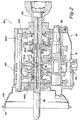
- Fig. 2 is a partial plan view, in section, illustrating a transmission and housing of the type shown in Fig. 1.
- Fig. 3 is a perspective view of the castings utilized to assemble the transmission housing of the present invention.
- Fig. 4 is a perspective view of the clutch housing piece casting of the housing of Fig. 3.
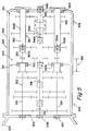
- Fig. 5 is a top view schematic illustration of an alternate embodiment of the present invention.
- compound transmission is used to designate a change-speed or change-gear transmission having a main transmission section and an auxiliary transmission section connected in series whereby the selected gear reduction in the main transmission section may be compounded by further selected gear reduction in the auxiliary transmission section.
- Transmission 110 of the present invention may be seen by reference to Figs. 1 and 2.
- Transmission 110 includes a main section 112 and an auxiliary section 114, both contained within housing 116.
- Housing 116 includes a forward end wall 116A and a rearward end wall 116B, but not an intermediate wall.
- Input shaft 118 carries input gear 120 fixed for rotation therewith and defines a rearwardly opening pocket 118A wherein a reduced diameter extension 158A of output shaft 158 is piloted.
- a non-friction bushing 1188 or the like may be provided in pocket or blind bore 118A.
- the forward end of input shaft 118 is supported by bearing 118C in front end wall 116A while the rearward end 158C of output shaft 158 is supported by bearing assembly 158D in rear and wall 116B.
- Bearing assembly 158D may be a pair of opposed taper bearings or a single roller or ball bearing.
- Input shaft 118 carries a master friction clutch MC for drivingly coupling the crankshaft of engine E to the input shaft.
- the mainshaft 146 which carries mainshaft clutches 148 and 150, and the mainshaft splitter clutch 180 is in the form of a generally tubular body 146A having an externally splined outer surface 146B and an axially extending through bore 146C for passage of output shaft 158. Shift forks 148A and 150A are provided for shifting clutches 148 and 150, respectively.
- Mainshaft 146 is independently rotatable relative to input shaft 118 and output shaft 158 and preferably is free for limited radial movements relative thereto.
- the main section 112 includes two substantially identical main section countershaft assemblies 122 each comprising a main section countershaft 124 carrying countershaft gears 130, 132, 134, 136 and 138 fixed thereto. Gear pairs 130, 134, 136 and 138 are constantly meshed with input gear 118, mainshaft gears 140 and 142 and idler 157, which is meshed with reverse mainshaft gear 144, respectively.
- Multiple, substantially identical countershaft structures are well known in the prior art, as may be seen by reference to U.S. Pats. No. 3,105,395 and 3,335,616.
- Main section countershaft 124 extends rearwardly into the auxiliary section, where its rearward end 124A is supported directly or indirectly in rear housing end wall 1168.
- the auxiliary section 114 includes two substantially identical auxiliary countershaft assemblies 160, each including an auxiliary countershaft 162 carrying auxiliary countershaft gears 168, 170 and 172 for rotation therewith.
- Auxiliary countershaft gear pairs 168, 170 and 172 are constantly meshed with splitter gear 174, splitter/range gear 176 and range gear 178, respectively.
- Splitter clutch 180 is fixed to mainshaft 146 for selectively clutching either gear 174 or 176 thereto while synchronized range clutch 182 is fixed to output shaft 158 for selectively clutching either gear 176 or gear 178 thereto.
- Auxiliary countershafts 162 are generally tubular in shape defining a through bore 162A for receipt of the rearward extensions of the main section countershafts 124.
- Bearings or bushings 162B and 162C are provided to rotatably support auxiliary countershaft 162 on main section countershaft 124.
- Bearing 162D directly or indirectly supports the rear ends of countershafts 124 and 162 in the rear end wall 116B.
- Mainshaft 146 is supported solely by the input and/or output shaft, one of the countershafts, main section countershafts 124, extends from the front end wall 116A to the rear end wall 116B and the other countershafts, auxiliary countershafts 162, are tubular members telescopically surrounding the one of the countershafts. As described in aforementioned U.S. Pats. No. 5,370,013 and 5,390,561, this improved structure allows elimination of the intermediate wall bearings.
- the input shaft 118 could extend further rearwardly to adjacent the rear end wall 116B or the input and output shafts could have inner ends meeting for mutual support at a point intermediate the end walls of the transmission (see Fig. 2).
- One or more of the jaw clutches 148, 150 and/or 180 could be blocked and/or synchronized. While the structure of the present invention is especially advantageous for multiple, substantially identical countershaft type transmissions, it is also applicable to single countershaft and swap-shaft-type transmissions.
- main section clutches 148 and 150 are controlled by shift forks 148A and 150A, respectively, associated with a shift shaft mechanism 188, preferably a single-shift-shaft-type mechanism of the type described in U.S. Pats. No. 4,621,537 and 4, 920, 815.
- the splitter clutch 180 and range clutch 182 are controlled by shift forks 180A and 182A, respectively, controlled by individual and independent 2- or 3-position actuators.
- the splitter and range actuators are pressurized, fluid-actuated piston/cylinder assemblies (see U.S. Pats. No. 5,199,312 and 5,222,404).
- the transmission housing 116 comprises two major pieces, an extended generally cup-shaped gear housing piece 190 and a generally cup-shaped clutch housing piece 192.
- the castings C190 and C192 for the housing C116 are shown in Figs. 3 and 4.
- the gear housing piece 190 includes a base 194 which defines the rear end wall 116B, and a generally tubular portion 196 which surrounds and encloses the gearing and extends from the base to a flanged opening 198, which will receive a mating flange 200 provided on the clutch housing piece 192.
- the upper area of the tubular portion 196 is provided with a shift lever housing opening 202 and a plurality of axially extending bores, 204, 206, 208 and 210, for receiving the splitter piston assembly, the single shift shaft 188, the range piston assembly, and a filter/regulator.
- the base portion 194 of gear housing piece 190 may include integral covers for the rear countershaft bearings 162A, or separate, removable covers 212 may be utilized.
- the gearing housing casting C190 will also include provisions for PTO openings, as at 214.
- the clutch housing piece 192 will include a flanged base portion 216 defining forward end wall 116A and an outwardly and forwardly extending tubular portion 218 terminating at a forward flanged portion 220 for mounting to the vehicular engine and enclosing the master clutch.
- the tubular portion 210 preferably, will include an access opening 222 for clutch adjustment and the like.
- Transmission 300 may be seen by reference to Fig. 5.
- Fig. 5 there is schematically illustrated a well known and highly commercially successful 18-speed compound transmission 300.
- Transmission 300 comprises a main transmission section 302 connected in series with an auxiliary transmission section 304 having both range and splitter type gearing.
- transmission 300 is housed within a single housing 306 and includes an input shaft 316 driven by a prime mover such as diesel engine through a selectively disengaged, normally engaged master friction clutch.
- Transmission 300 is a "(4+1) ⁇ (2) ⁇ (2)" type compound transmission wherein the main section 302 and auxiliary section 304 are contained within a common housing 306 having a forward end wall 308, a rearward end wall 310 and a partial intermediate wall 312.
- Input shaft 316 carries an input gear fixed for rotation therewith and defines an inwardly extending reduced diameter portion, which directly or indirectly supports the front end of mainshaft 346.
- Output shaft 358 extends from the rear end of transmission 300 and carries an output flange. The inner end of output shaft 358 is provided with a tapered surface for direct or indirect support of the rear end of mainshaft 346.
- Input shaft 316 is supported in front end wall 308 by taper roller bearing 318B, while output shaft 358 is supported in rear end wall 316B by dual taper roller bearing assembly 358E.
- the mainshaft 346 carries mainshaft clutches and the splitter clutch and extends generally coaxially between and is supported by the inner ends of the input and output shafts.
- Mainshaft gears, a splitter gear and a splitter/range gear surround the mainshaft, preferably for limited radial movement relative thereto, and are selectively clutchable thereto by the clutches.
- a range clutch is carried by output shaft 358, which is surrounded by the splitter/range gear and a range gear. The range clutch is effective to clutch either gear to the output shaft 358.
- the function and operation of the auxiliary section of transmission 300 is the same as that of transmission discussed above.
- the main and auxiliary section countershaft assemblies, 322 and 360, respectively, are substantially functionally and operatively identical to the main section and auxiliary section countershaft assemblies of transmission 110, described above.
- the forward ends 362A of the auxiliary countershaft(s) 362 are generally tubular and telescopically surround the rear end 324A of the main section countershafts and are directly or indirectly rotatably supported by bearings 362B thereon.
- a bearing 326 supports the forward end of main section countershaft 324 in front wall 214A, while a bearing 362C supports the rearward end of auxiliary section countershaft 362 in the rear end wall 214B.
- the rearward end 324A of main section countershaft 324 is supported by bearing 342B in partial intermediate wall 312, while the forward end 362A of auxiliary countershaft 362 is supported by bearing 362B, carried by a cantilevered rearward end of main countershaft 324.
- the mainshaft 346 is thus supported directly or indirectly at its front end by input shaft 316 for a limited amount of radial movement of the mainshaft relative to the axis of rotation of the input shaft.
- the mainshaft is supported directly or indirectly at its rear end by the output shaft 358 for a limited amount of radial movement of the mainshaft relative to the axis of rotation of the output shaft 358.
- the intermediate wall 312 may be of minimal size.
- the intermediate wall 312 and the bearings 324B supporting the rearward ends of the front or main section countershafts 324 are located within the axial space 380 required for clutch 64 and its forward and/or rearward travel. Accordingly, the addition of the partial intermediate wall 312 and bearings 324B adds little or no axial length to the transmission 300 as compared to transmissions without an intermediate wall, as seen in aforementioned U.S. Pats. No. 5,370,013 and 5,390,561.
- the reverse idler 318 is of a relatively enlarged pitch diameter, larger than the pitch diameter of reverse countershaft gear 320, which allows both the reverse mainshaft gear 323 and the reverse countershaft gear 320 to be of a relatively reduced pitch diameter.
- This allows the inner diameter of bearing 342B to be assembled over the reverse countershaft gear, formed directly on the outer diameter of main section countershaft 324, and permits the main section reverse gear 323 to pass through the central opening in the intermediate wall 312 for assembly purposes.
- the reverse idler (shown out of position) preferably is mounted on an idler shaft cantilever-mounted in housing 306.
- the housing 306 is formed of an elongated cup-shaped gear housing piece 328 and a cup-shaped clutch housing piece 330, the major difference being that the gear housing piece 320 defines the partial intermediate wall portion 312.
- an improved housing for a compound change-gear transmission comprising two major pieces, an elongated cup-shaped gear housing piece and a cup-shaped clutch housing piece, is provided.
Landscapes
- Engineering & Computer Science (AREA)
- General Engineering & Computer Science (AREA)
- Mechanical Engineering (AREA)
- General Details Of Gearings (AREA)
- Structure Of Transmissions (AREA)
- Arrangement Of Transmissions (AREA)
Claims (10)
- Getriebegehäuse (116, 306) für ein Verbundgetriebe mit einem Hauptgetriebeabschnitt (112,302), der in Reihe mit einem Hilfsgetriebeabschnitt (114,304) liegt,wobei das Gehäuse (116, 306) eine vordere Stirnwand (116A,308) mit Ausnehmungen aufweist, um Lager (118C) aufzunehmen, in denen Wellen (122,124,146A) gelagert sind, die sich in den Hauptgetriebeabschnitt (112, 302) hinein erstrecken, und eine rückwärtige Stirnwand (116B,316B) mit Ausnehmungen umfasst, um Lager (158D) aufzunehmen, in denen Wellen (124,162,362) gelagert sind, die sich in die Hilfsgetriebegruppe (114,304) hinein erstrecken, und zu dem gehören:ein längliches, becherförmiges Getriebegehäuseteil (190) mit einem Grundabschnitt (194), der die rückwärtige Stirnwand (116B,316B) bildet, und mit einem im Wesentlichen rohrförmigen Abschnitt (196), der sich aus dem Grundabschnitt heraus hin zu einer Flanschöffnung (198) erstreckt; undein im Wesentlichen schalenförmiger Kupplungsgehäuseabschnitt (192), der mit einem Grundabschnitt (200) mit Flansch zur Befestigung an der Flanschöffnung (198) versehen ist, und die vordere Stirnwand (116A,308) bildet sowie einen nach außen und nach vorne sich erweiterten Abschnitt (218,330) zur Befestigung an einem Motor (E) aufweist, der ein Gehäuse bildet, das die Hauptkupplung (MC) eines Fahrzeugs umgibt,wobei das Gehäuse derart dimensioniert ist, dass es ein Verbundgetriebe aufnehmenkann, zu dem der Hauptgetriebeabschnitt (112, 302) und der mit diesem in Reihe liegende Hilfsgetriebeabschnitt (114, 304) gehören.
- Gehäuse nach Anspruch 1, bei dem der rohrförmige Abschnitt (196) mehrere Bohrungen (202,214) aufweist, um Getriebeschaltkomponenten aufzunehmen.
- Gehäuse nach Anspruch 1, bei dem der rohrförmige Abschnitt (196) eine Teilzwischenwand (312) aufweist.
- Stufenverbundgetriebe, zu dem eine mehrgängige Hauptgetriebegruppe (112,302) und eine mit dieser in Reihe liegende, mehrgängige Hilfsgetriebegruppe (114,304) gehören,wobei das Stufenverbundgetriebe in der Bauart entweder mit Range-Gruppe oder mit Split-Gruppe oder mit kombinierter Split-Range-Gruppe ausgeführt ist, die Haupt- und die Hilfsgetriebegruppe (114,304) in einem gemeinsamen Gehäuse (116,306) enthalten sind, das eine vordere Stirnwand (116A,308) und eine rückwärtige Stirnwand (116B,316B) bildet,die Hauptgetriebegruppe (112,302) eine Hauptgruppen-Vorgelegewelle (122,324) aufweist, die wenigstens zwei daran befestigte Hauptgruppenvorgelegewellenzahnräder (134...138) enthält unddie Hilfsgetriebegruppe (114,304) eine Hilfsgruppenvorgelegewelle (160,362) aufweist, die wenigstens zwei Hilfsgruppenvorgelegezahnräder (168...172) drehfest trägt,die Haupt- und Hilfsgruppen-Vorgelegewellen (122,324; 162,362) unabhängig voneinander drehbar und koaxial zueinander angeordnet sind, und zusammen eine koaxiale Anordnung von Vorgelegewellen bilden, die in dem Gehäuse (116,306) ausschließlich mittels Lagern (126,326,162D,362C) drehbar gelagert sind, die von der vorderen und der rückwärtigen Stirnwand (116A,308;116B,316B) getragen werden;wobei zu dem Gehäuse (116,306) gehören:ein längliches, becherförmiges Getriebegehäuseteil (190) mit einem Grundabschnitt (194), der die rückwärtige Stirnwand (116B,316B) bildet, und mit einem im Wesentlichen rohrförmigen Abschnitt (196), der sich von dem Grundabschnitt weg hin zu einer Flanschöffnung (198) erstreckt undein im Wesentlichen schalenförmiger Kupplungsgehäuseabschnitt (192), der mit einem Grundabschnitt (200) mit Flansch zur Befestigung an der Flanschöffnung (198) versehen ist und die vordere Stirnwand (116A,308) bildet sowie einen nach außen und nach vorne sich erweiterten Abschnitt (218,330) für die Befestigung an einem Motor (E) aufweist, der ein Gehäuse bildet, das die Hauptkupplung (MC) eines Fahrzeugs umgibt,wobei das Gehäuse derart dimensioniert ist, dass es ein Verbundgetriebe aufzunehmen kann, zu dem der Hauptgetriebeabschnitt (112,302) und der mit diesem in Reihe liegende Hilfsgetriebeabschnitt (114,304) gehören.
- Getriebe nach Anspruch 4, bei dem der rohrförmige Abschnitt (196) mehrere Bohrungen (202,214) aufweist, um Getriebeschaltvorrichtungen aufzunehmen.
- Für ein Fahrzeug geeignetes Geschwindigkeitswechselgetriebe in Verbundbauart, zu dem gehören: eine Hauptgetriebegruppe mit mehreren Gängen (112,302), die in Reihe mit einer Hilfsgetriebegruppe (114,304) liegt, wobei die Haupt- und Hilfsgetriebeabschnitte in einem gemeinsamen Getriebegehäuse (116, 306) enthalten sind, das eine vordere Stirnwand (116A, 308) und eine rückwärtige Stirnwand (116B,316B) aufweist;wobei zu dem Hauptgetriebeabschnitt (112,302) gehören: eine Eingangswelle (118, 316), die drehbar in dem Gehäuse (116,306) mittels Eingangswellenlagermitteln (118C,318B) gelagert ist, die von der vorderen Stirnwand (116A,308) getragen werden, wenigstens ein Eingangszahnrad (120), das mit der Eingangswelle (118,316) zu kuppeln ist, eine zu der Eingangswelle (118,316) im Wesentlichen koaxiale Hauptwelle (146,346), die sich in die Hilfsgetriebegruppe (114,304) hinein erstreckt, mehrere, im Wesentlichen identische Hauptgruppen-Vorgelegewellen (124,324), die in dem Gehäuse drehbar gelagert sind und durch die Eingangswelle (118,316) angetrieben werden, mehrere Hauptgruppen-Vorgelegewellenzahnräder (134...138), die an jeder der Hauptgruppen-Vorgelegewellen (124,324) befestigt sind, mehrere Hauptwellenzahnräder (140,144), die die Hauptwelle (146, 346) umgeben und ständig mit Paaren von Hauptgruppenvorgelegewellenzahnrädern (134...138) kämmen sowie Hauptgruppenkupplungsmittel (148,150), die von der Hauptwelle (146,346) getragen werden, um wahlweise die Hauptwellenzahnräder (140...144) drehfest mit der Hauptwelle (146,346) zu kuppeln;wobei zu der Hilfsgetriebegruppe (114,304) gehören: mehrere, im Wesentlichen identische Hilfsgruppen-Vorgelegewellen (162,362), die koaxial zu den Hauptgruppen-Vorgelegewellen (124,324) angeordnet und in dem Gehäuse (116,306) drehbar gelagert sind, eine zu der Hauptwelle (146,346) im Wesentlichen koaxiale und drehbar in dem Gehäuse (116,306) gelagerte Ausgangswelle (158,358), die mittels Ausgangswellenlagermitteln (158D,358E) von der rückwärtigen Stirnwand (116B,316B) getragen wird, ein Hilfsgruppen-Vorgelegewellenzahnrad (168...172), das an jeder der Hilfsgruppen-Vorgelegewellen (162,362) befestigt ist, wenigstens ein zentrales Hilfsgruppenzahnrad (174...178), das im Wesentlichen zu der Ausgangswelle (158,358E) koaxial angeordnet ist und ständig mit einem Paar von Hilfsgruppen-Vorgelegewellenzahnrädern (168...172) kämmt, und Hilfsgruppenkupplungsmittel (180,182), um wahlweise wenigstens eines der zentralen Hilfsgruppenzahnräder (174,178) sowie die Hauptwelle (146,346) an die Ausgangswelle (158,358) anzukuppeln;wobei die zueinander koaxialen Gruppen aus Vorgelegewellen der Hauptgruppe und Vorgelegewelle der Hilfsgruppe (122,322;162,362) mittels Lagermitteln (162B,162C,324), die zwischen diesen angeordnet sind, unabhängig voneinander drehbar in dem Gehäuse (116,306) gelagert sind und gemeinsam eine koaxiale Anordnung von Vorgelegewellen bilden, die in dem Gehäuse (116,306) lediglich mittels in der vorderen Stirnwand (116A,308) und in der rückwärtigen Stirnwand (116B, 316B) befestigten Lagermitteln (126, 326) sowie mittleren Lagermitteln (342B) drehbar gelagert sind, die in einer mittleren Gehäusewand (312) befestigt sind, die axial mit einem der Hauptgruppenkupplungsmittel (148...180) fluchtet; wobei das Getriebe dadurch gekennzeichnet ist, dass zu dem Gehäuse (116,306) gehören:ein längliches, becherförmiges Getriebegehäuseteil (190) mit einem Grundabschnitt (194), der die rückwärtige Stirnwand (116B, 316B) bildet, und mit einem im Wesentlichen rohrförmigen Abschnitt (196), der sich aus dem Grundabschnitt heraus hin zu einer Flanschöffnung (198) erstreckt; undein im Wesentlichen schalenförmiger Kupplungsgehäuseabschnitt (192), der mit einem Grundabschnitt (200) mit Flansch zur Befestigung an der Flanschöffnung (198) versehen ist und die vordere Stirnwand (116A,308) bildet sowie einen nach außen und nach vorne sich erweiterten Abschnitt (218,330) zur Befestigung an einem Motor (E) aufweist, der ein Gehäuse bildet, das die Hauptkupplung (MC) eines Fahrzeugs umgibt,wobei das Gehäuse derart dimensioniert ist, dass es ein Verbundgetriebe aufnehmen kann, zu dem der Hauptgetriebeabschnitt (112,302) und der mit diesem in Reihe liegende Hilfsgetriebeabschnitt (114,304) gehören.
- Getriebe nach Anspruch 6, bei dem der rohrförmige Abschnitt mehrere Bohrungen (202,214) aufweist, um Getriebeschaltvorrichtungen aufzunehmen.
- Getriebe nach Anspruch 7, ferner dadurch gekennzeichnet, dass die Hauptwelle (146,346) in dem Gehäuse (116,306) ausschließlich durch die Eingangswelle (118,316) und die Ausgangswelle (158,358) getragen wird.
- Getriebe nach Anspruch 6, ferner dadurch gekennzeichnet, dass die Hauptwelle (146,346) in dem Gehäuse ausschließlich durch die Eingangswelle (118,316) und die Ausgangswelle (158,358) getragen wird.
- Getriebe nach Anspruch 6, bei dem eine der Hauptwellenkupplungen (180) wahlweise in einem axialen Raum verschieblich ist, um ein ausgewähltes Hauptwellenzahnrad einer niedrigsten Vorwärtsgangstufe bzw. ein Hauptwellenzahnrad einer Rückwärtsgangstufe mit der Hauptwelle (146) wahlweise in Eingriff zu bringen bzw. aus dem Eingriff zu nehmen, wobei sich die mittleren Lagermittel (342B) und die mittlere Gehäusewand (312) innerhalb dieses axialen Raumes befinden.
Applications Claiming Priority (2)
| Application Number | Priority Date | Filing Date | Title |
|---|---|---|---|
| US08/627,808 US5737978A (en) | 1996-04-10 | 1996-04-10 | Two-piece housing for compound transmission |
| US627808 | 1996-04-10 |
Publications (3)
| Publication Number | Publication Date |
|---|---|
| EP0801251A2 EP0801251A2 (de) | 1997-10-15 |
| EP0801251A3 EP0801251A3 (de) | 1998-04-08 |
| EP0801251B1 true EP0801251B1 (de) | 2001-09-26 |
Family
ID=24516218
Family Applications (1)
| Application Number | Title | Priority Date | Filing Date |
|---|---|---|---|
| EP97105529A Expired - Lifetime EP0801251B1 (de) | 1996-04-10 | 1997-04-03 | Zweiteiliges Gehäuse für ein Verbundgetriebe |
Country Status (6)
| Country | Link |
|---|---|
| US (1) | US5737978A (de) |
| EP (1) | EP0801251B1 (de) |
| JP (1) | JPH1030711A (de) |
| CN (1) | CN1166579A (de) |
| BR (1) | BR9700533A (de) |
| DE (1) | DE69706909T2 (de) |
Families Citing this family (18)
| Publication number | Priority date | Publication date | Assignee | Title |
|---|---|---|---|---|
| AU714241B2 (en) * | 1996-10-09 | 1999-12-23 | Select Design Technologies Limited | Smart matic transmission |
| US5988341A (en) * | 1997-08-01 | 1999-11-23 | Meritor Heavy Vehicle Systems, Llc | Transmission input bearing retainer |
| US5907974A (en) * | 1998-04-29 | 1999-06-01 | Eaton Corporation | Splitter lockout system arranged for conversion between first and second owner configurations |
| GB9828452D0 (en) | 1998-12-24 | 1999-02-17 | Eaton Corp | Automated transmission downshift control |
| US6325743B1 (en) | 1999-01-14 | 2001-12-04 | Eaton Corporation | Automated transmission upshift control |
| US6149545A (en) * | 1999-01-14 | 2000-11-21 | Eaton Corporation | Automated transmission upshift control |
| US6113516A (en) * | 1999-01-14 | 2000-09-05 | Eaton Corporation | Adaptive automated transmission upshift control |
| US6146310A (en) * | 1999-01-15 | 2000-11-14 | Eaton Corporation | Adaptive automated transmission downshift control |
| US6066071A (en) * | 1999-01-15 | 2000-05-23 | Eaton Corporation | Automated transmission downshift control |
| US6123644A (en) * | 1999-07-19 | 2000-09-26 | Eaton Corporation | Adaptive anti-hunt logic for automated transmission downshift control |
| US6126569A (en) * | 1999-07-19 | 2000-10-03 | Eaton Corporation | Starting and driveline shock protection control method and system |
| US6409629B1 (en) | 2000-05-17 | 2002-06-25 | Eaton Corporation | Automated transmission upshift control with upshift brake thermal protection |
| US6491603B1 (en) | 2000-09-12 | 2002-12-10 | Eaton Corporation | Automated transmission shift control |
| US6461273B1 (en) | 2001-06-01 | 2002-10-08 | Eaton Corporation | Automated transmission upshift brake control |
| KR100507151B1 (ko) * | 2002-08-12 | 2005-08-09 | 현대자동차주식회사 | 5단 및 6단 겸용 수동변속기 |
| JP6029212B2 (ja) * | 2013-09-04 | 2016-11-24 | 本田技研工業株式会社 | 車両用動力伝達装置 |
| JP6132751B2 (ja) * | 2013-11-25 | 2017-05-24 | 本田技研工業株式会社 | 動力伝達装置 |
| JP6156119B2 (ja) * | 2013-12-17 | 2017-07-05 | スズキ株式会社 | 動力伝達装置の組み付け構造および動力伝達装置の組み付け方法 |
Family Cites Families (12)
| Publication number | Priority date | Publication date | Assignee | Title |
|---|---|---|---|---|
| US3105395A (en) * | 1962-12-26 | 1963-10-01 | Eaton Mfg Co | Automotive device |
| DE1154355B (de) * | 1961-08-31 | 1963-09-12 | Zahnradfabrik Friedrichshafen | Gehaeuse fuer Wechselgetriebe von Kraftfahrzeugen |
| US3283613A (en) * | 1964-04-20 | 1966-11-08 | Eaton Yale & Towne | Automotive device |
| JPS53134166A (en) * | 1977-04-27 | 1978-11-22 | Toyota Motor Corp | Automatic transmission gear box |
| JPS57137765A (en) * | 1981-02-20 | 1982-08-25 | Nissan Motor Co Ltd | Air breather for change gear |
| US4754665A (en) * | 1986-02-05 | 1988-07-05 | Eaton Corporation | Auxiliary transmission section |
| JP3017751B2 (ja) * | 1989-05-10 | 2000-03-13 | アイシン・エィ・ダブリユ株式会社 | 自動変速機のドラムの支持装置 |
| US4944197A (en) * | 1989-06-07 | 1990-07-31 | Eaton Corporation | Resilient range interlock |
| US5404772A (en) * | 1992-11-06 | 1995-04-11 | Dana Corporation | Transmission housing |
| DE4238855C1 (de) * | 1992-11-18 | 1994-04-14 | Daimler Benz Ag | Getriebegehäuse für ein Gangwechselgetriebe der Umlaufräderbauart |
| US5370013A (en) * | 1993-05-20 | 1994-12-06 | Eaton Corporation | Helically geared compound transmission |
| US5390561A (en) * | 1993-05-20 | 1995-02-21 | Eaton Corporation | Compound transmission |
-
1996
- 1996-04-10 US US08/627,808 patent/US5737978A/en not_active Expired - Lifetime
-
1997
- 1997-04-03 EP EP97105529A patent/EP0801251B1/de not_active Expired - Lifetime
- 1997-04-03 DE DE69706909T patent/DE69706909T2/de not_active Expired - Fee Related
- 1997-04-08 JP JP9089278A patent/JPH1030711A/ja active Pending
- 1997-04-10 CN CN97110288A patent/CN1166579A/zh active Pending
- 1997-04-10 BR BR9700533A patent/BR9700533A/pt not_active IP Right Cessation
Also Published As
| Publication number | Publication date |
|---|---|
| EP0801251A3 (de) | 1998-04-08 |
| EP0801251A2 (de) | 1997-10-15 |
| CN1166579A (zh) | 1997-12-03 |
| MX9702629A (es) | 1997-10-31 |
| DE69706909D1 (de) | 2001-10-31 |
| US5737978A (en) | 1998-04-14 |
| DE69706909T2 (de) | 2002-06-13 |
| BR9700533A (pt) | 1998-11-03 |
| JPH1030711A (ja) | 1998-02-03 |
Similar Documents
| Publication | Publication Date | Title |
|---|---|---|
| EP0801251B1 (de) | Zweiteiliges Gehäuse für ein Verbundgetriebe | |
| KR100300293B1 (ko) | 복합변속기 | |
| CA2163050C (en) | High-capacity compound transmission | |
| US5845544A (en) | Control module | |
| EP0625652B1 (de) | Schrägverzahntes Verbundgetriebe | |
| EP0790435B1 (de) | Längenreduziertes Hochleistungs-Verbundgetriebe | |
| CA1302736C (en) | Countershaft transmission | |
| EP0800023B1 (de) | Handbetriebenes Wechselgetriebe mit verbessertem automatischen Gangwechsel | |
| EP0187750B1 (de) | Vorgelegewellen-getriebe | |
| JPS623009B2 (de) | ||
| US5832607A (en) | Method of making a transmission shaft | |
| US5309782A (en) | Multiple ratio manual transmission | |
| EP0999380B1 (de) | Mechanisches Getriebe mit verminderter Stufendifferrenz in den oberen Gängen | |
| MXPA97002629A (en) | Accommodation of two pieces for computer transmission | |
| CA1231556A (en) | Countershaft transmission | |
| JPH03189451A (ja) | 作業車の伝動構造 | |
| JPH0571523U (ja) | トランスミツシヨン構造 | |
| MXPA96000122A (en) | Mechanism of changes of a single arrow, better |
Legal Events
| Date | Code | Title | Description |
|---|---|---|---|
| PUAI | Public reference made under article 153(3) epc to a published international application that has entered the european phase |
Free format text: ORIGINAL CODE: 0009012 |
|
| AK | Designated contracting states |
Kind code of ref document: A2 Designated state(s): DE FR GB IT SE |
|
| PUAL | Search report despatched |
Free format text: ORIGINAL CODE: 0009013 |
|
| AK | Designated contracting states |
Kind code of ref document: A3 Designated state(s): DE FR GB IT SE |
|
| 17P | Request for examination filed |
Effective date: 19980610 |
|
| 17Q | First examination report despatched |
Effective date: 19990907 |
|
| GRAG | Despatch of communication of intention to grant |
Free format text: ORIGINAL CODE: EPIDOS AGRA |
|
| GRAG | Despatch of communication of intention to grant |
Free format text: ORIGINAL CODE: EPIDOS AGRA |
|
| GRAH | Despatch of communication of intention to grant a patent |
Free format text: ORIGINAL CODE: EPIDOS IGRA |
|
| GRAH | Despatch of communication of intention to grant a patent |
Free format text: ORIGINAL CODE: EPIDOS IGRA |
|
| GRAA | (expected) grant |
Free format text: ORIGINAL CODE: 0009210 |
|
| AK | Designated contracting states |
Kind code of ref document: B1 Designated state(s): DE FR GB IT SE |
|
| REF | Corresponds to: |
Ref document number: 69706909 Country of ref document: DE Date of ref document: 20011031 |
|
| REG | Reference to a national code |
Ref country code: GB Ref legal event code: IF02 |
|
| ET | Fr: translation filed | ||
| PLBE | No opposition filed within time limit |
Free format text: ORIGINAL CODE: 0009261 |
|
| STAA | Information on the status of an ep patent application or granted ep patent |
Free format text: STATUS: NO OPPOSITION FILED WITHIN TIME LIMIT |
|
| 26N | No opposition filed | ||
| PGFP | Annual fee paid to national office [announced via postgrant information from national office to epo] |
Ref country code: FR Payment date: 20050401 Year of fee payment: 9 |
|
| PGFP | Annual fee paid to national office [announced via postgrant information from national office to epo] |
Ref country code: IT Payment date: 20060430 Year of fee payment: 10 |
|
| REG | Reference to a national code |
Ref country code: FR Ref legal event code: ST Effective date: 20061230 |
|
| PG25 | Lapsed in a contracting state [announced via postgrant information from national office to epo] |
Ref country code: FR Free format text: LAPSE BECAUSE OF NON-PAYMENT OF DUE FEES Effective date: 20060502 |
|
| PGFP | Annual fee paid to national office [announced via postgrant information from national office to epo] |
Ref country code: GB Payment date: 20080317 Year of fee payment: 12 |
|
| PGFP | Annual fee paid to national office [announced via postgrant information from national office to epo] |
Ref country code: DE Payment date: 20080430 Year of fee payment: 12 |
|
| PGFP | Annual fee paid to national office [announced via postgrant information from national office to epo] |
Ref country code: SE Payment date: 20080404 Year of fee payment: 12 |
|
| PG25 | Lapsed in a contracting state [announced via postgrant information from national office to epo] |
Ref country code: IT Free format text: LAPSE BECAUSE OF NON-PAYMENT OF DUE FEES Effective date: 20070403 |
|
| EUG | Se: european patent has lapsed | ||
| GBPC | Gb: european patent ceased through non-payment of renewal fee |
Effective date: 20090403 |
|
| PG25 | Lapsed in a contracting state [announced via postgrant information from national office to epo] |
Ref country code: DE Free format text: LAPSE BECAUSE OF NON-PAYMENT OF DUE FEES Effective date: 20091103 |
|
| PG25 | Lapsed in a contracting state [announced via postgrant information from national office to epo] |
Ref country code: GB Free format text: LAPSE BECAUSE OF NON-PAYMENT OF DUE FEES Effective date: 20090403 |
|
| PG25 | Lapsed in a contracting state [announced via postgrant information from national office to epo] |
Ref country code: SE Free format text: LAPSE BECAUSE OF NON-PAYMENT OF DUE FEES Effective date: 20090404 |