EP0801266A2 - Chapeau pour cheminée d'une installation de chauffage - Google Patents
Chapeau pour cheminée d'une installation de chauffage Download PDFInfo
- Publication number
- EP0801266A2 EP0801266A2 EP97201050A EP97201050A EP0801266A2 EP 0801266 A2 EP0801266 A2 EP 0801266A2 EP 97201050 A EP97201050 A EP 97201050A EP 97201050 A EP97201050 A EP 97201050A EP 0801266 A2 EP0801266 A2 EP 0801266A2
- Authority
- EP
- European Patent Office
- Prior art keywords
- condensate
- condensate collecting
- exhaust pipe
- attachment
- roof
- Prior art date
- Legal status (The legal status is an assumption and is not a legal conclusion. Google has not performed a legal analysis and makes no representation as to the accuracy of the status listed.)
- Granted
Links
- 238000010438 heat treatment Methods 0.000 title claims abstract description 44
- 239000007789 gas Substances 0.000 claims description 29
- 239000004020 conductor Substances 0.000 claims description 3
- 230000000284 resting effect Effects 0.000 claims 1
- 229910052782 aluminium Inorganic materials 0.000 abstract description 3
- XAGFODPZIPBFFR-UHFFFAOYSA-N aluminium Chemical compound [Al] XAGFODPZIPBFFR-UHFFFAOYSA-N 0.000 abstract description 3
- XLYOFNOQVPJJNP-UHFFFAOYSA-N water Substances O XLYOFNOQVPJJNP-UHFFFAOYSA-N 0.000 abstract description 2
- 239000004411 aluminium Substances 0.000 abstract 1
- 230000015572 biosynthetic process Effects 0.000 description 3
- 238000009833 condensation Methods 0.000 description 2
- 230000005494 condensation Effects 0.000 description 2
- 238000010276 construction Methods 0.000 description 2
- 230000002093 peripheral effect Effects 0.000 description 2
- 238000001816 cooling Methods 0.000 description 1
- 238000007710 freezing Methods 0.000 description 1
- 230000008014 freezing Effects 0.000 description 1
- 238000009413 insulation Methods 0.000 description 1
- 238000004519 manufacturing process Methods 0.000 description 1
- 239000000463 material Substances 0.000 description 1
- 229910052751 metal Inorganic materials 0.000 description 1
- 239000002184 metal Substances 0.000 description 1
- 230000002787 reinforcement Effects 0.000 description 1
Images


Classifications
-
- F—MECHANICAL ENGINEERING; LIGHTING; HEATING; WEAPONS; BLASTING
- F24—HEATING; RANGES; VENTILATING
- F24H—FLUID HEATERS, e.g. WATER OR AIR HEATERS, HAVING HEAT-GENERATING MEANS, e.g. HEAT PUMPS, IN GENERAL
- F24H8/00—Fluid heaters characterised by means for extracting latent heat from flue gases by means of condensation
- F24H8/006—Means for removing condensate from the heater
-
- F—MECHANICAL ENGINEERING; LIGHTING; HEATING; WEAPONS; BLASTING
- F23—COMBUSTION APPARATUS; COMBUSTION PROCESSES
- F23J—REMOVAL OR TREATMENT OF COMBUSTION PRODUCTS OR COMBUSTION RESIDUES; FLUES
- F23J13/00—Fittings for chimneys or flues
- F23J13/02—Linings; Jackets; Casings
- F23J13/025—Linings; Jackets; Casings composed of concentric elements, e.g. double walled
-
- F—MECHANICAL ENGINEERING; LIGHTING; HEATING; WEAPONS; BLASTING
- F23—COMBUSTION APPARATUS; COMBUSTION PROCESSES
- F23L—SUPPLYING AIR OR NON-COMBUSTIBLE LIQUIDS OR GASES TO COMBUSTION APPARATUS IN GENERAL ; VALVES OR DAMPERS SPECIALLY ADAPTED FOR CONTROLLING AIR SUPPLY OR DRAUGHT IN COMBUSTION APPARATUS; INDUCING DRAUGHT IN COMBUSTION APPARATUS; TOPS FOR CHIMNEYS OR VENTILATING SHAFTS; TERMINALS FOR FLUES
- F23L17/00—Inducing draught; Tops for chimneys or ventilating shafts; Terminals for flues
- F23L17/02—Tops for chimneys or ventilating shafts; Terminals for flues
- F23L17/14—Draining devices
-
- F—MECHANICAL ENGINEERING; LIGHTING; HEATING; WEAPONS; BLASTING
- F23—COMBUSTION APPARATUS; COMBUSTION PROCESSES
- F23J—REMOVAL OR TREATMENT OF COMBUSTION PRODUCTS OR COMBUSTION RESIDUES; FLUES
- F23J2211/00—Flue gas duct systems
- F23J2211/10—Balanced flues (combining air supply and flue gas exhaust)
- F23J2211/101—Balanced flues (combining air supply and flue gas exhaust) with coaxial duct arrangement
-
- F—MECHANICAL ENGINEERING; LIGHTING; HEATING; WEAPONS; BLASTING
- F23—COMBUSTION APPARATUS; COMBUSTION PROCESSES
- F23J—REMOVAL OR TREATMENT OF COMBUSTION PRODUCTS OR COMBUSTION RESIDUES; FLUES
- F23J2213/00—Chimneys or flues
- F23J2213/30—Specific materials
- F23J2213/303—Specific materials metallic
-
- F—MECHANICAL ENGINEERING; LIGHTING; HEATING; WEAPONS; BLASTING
- F23—COMBUSTION APPARATUS; COMBUSTION PROCESSES
- F23J—REMOVAL OR TREATMENT OF COMBUSTION PRODUCTS OR COMBUSTION RESIDUES; FLUES
- F23J2900/00—Special arrangements for conducting or purifying combustion fumes; Treatment of fumes or ashes
- F23J2900/13004—Water draining devices associated with flues
-
- Y—GENERAL TAGGING OF NEW TECHNOLOGICAL DEVELOPMENTS; GENERAL TAGGING OF CROSS-SECTIONAL TECHNOLOGIES SPANNING OVER SEVERAL SECTIONS OF THE IPC; TECHNICAL SUBJECTS COVERED BY FORMER USPC CROSS-REFERENCE ART COLLECTIONS [XRACs] AND DIGESTS
- Y02—TECHNOLOGIES OR APPLICATIONS FOR MITIGATION OR ADAPTATION AGAINST CLIMATE CHANGE
- Y02B—CLIMATE CHANGE MITIGATION TECHNOLOGIES RELATED TO BUILDINGS, e.g. HOUSING, HOUSE APPLIANCES OR RELATED END-USER APPLICATIONS
- Y02B30/00—Energy efficient heating, ventilation or air conditioning [HVAC]
Definitions
- the invention relates to an attachment for an exhaust pipe of a heating system with a shielding element to be arranged at least in regions above the exhaust pipe, which defines at least one exhaust gas outlet opening, and with a condensate collecting element arranged below the shielding element outside the exhaust pipe, the upper side of which has a condensate collecting surface for formed on the shielding element Condensate is formed.
- the shielding element can comprise a radially outwardly projecting side wall and a bottom wall.
- Such attachments are intended to ensure that the exhaust gas outflow from the exhaust pipe is as uniform as possible, even under different weather conditions, such as more or less strong cross winds, which is important for economical heating operation.
- larger amounts of condensed water may form on the attachment. If the outside temperature is below freezing, ice can form in the area of the attachment. This changes the flow conditions in the attachment; in the worst case, exhaust gas outlet openings can be closed.
- the invention has for its object to provide an attachment for exhaust pipes of the type mentioned with reduced risk of icing.
- the condensate collecting element can be heated by the exhaust gases or electrically. Because the condensate collecting element is heated by the exhaust gases, those areas too of the attachment, which are not directly exposed to the exhaust gas stream, are heated sufficiently during operation to prevent ice formation. In heating systems with a particularly low exhaust gas temperature, as an alternative or in addition to the heating of the exhaust gases, electrical heating can also be provided to avoid ice formation under all circumstances.
- the condensate collecting element with electrical heating or the heating thereof from the exhaust gases, since the condensate collecting element is at least in regions outside the direct exhaust gas flow.
- the exhaust gas outlet openings or fresh air supply openings between the xondensate collecting element and the shielding element so that icing of the condensate collecting element that has been possible up to now leads to the closure of just these openings.
- the condensate collecting element preferably consists of a material which is a good heat conductor, such as aluminum.
- the shielding element usually has a significantly larger diameter, such as the exhaust pipe, to be together with the z. B. at the top and bottom of the shielding element formed exhaust outlet openings largely constant outflow resistance for the exhaust gas even under a wide variety of weather conditions, especially wind speeds ensure.
- the shielding element be thermally coupled to the condensate collecting element.
- the shielding element can be connected via webs to a central collar through which the exhaust gas flows.
- At least one heating element can be inserted into the condensate collecting element.
- the condensate collecting element can be provided with at least one temperature sensor. It is also conceivable to use heating elements which have an electrical resistance falling with falling temperature, so that the control or regulation by a temperature sensor can be dispensed with.
- the condensate collecting surface runs obliquely inwards and opens into the exhaust pipe directly or via at least one connecting channel.
- the condensate collecting element conducts the condensate to the outside.
- the condensate collecting surface preferably collects condensate dripping from the side wall of the shielding element and from a roof element of the shielding element that may be provided.
- the roof element is formed with at least one preferably substantially annular drip edge in the area above the condensate collecting surface or above the inner peripheral surface of the side wall.
- the roof element can be designed with a drip area above the exhaust pipe.
- a return of the condensate from the roof element over the inner circumferential surface of the side wall or the condensate collecting surface of the condensate collecting element is in principle also possible, although less preferred, since a higher heating capacity may then be necessary to avoid icing.
- the draining area is preferably formed by a downward-pointing conical tip of the roof element.
- the invention further relates to a kit for a roof duct of an exhaust pipe of a heating system, comprising an attachment, in particular as described above.
- the attachment be provided with a separate condensate collecting element, a separate side wall that can be connected to it, and a separate one with the side wall and / or to form the roof element that can be connected to the condensate collecting element, with either a condensate collecting element with condensate drainage inwards into the exhaust pipe or a condensate drainage element with condensate drainage to the outside, and the roof element can optionally be omitted.
- the separate side wall which can be provided at its upper end with a fastening device for the roof element, in particular in the form of an outer retaining ring, and at its lower end with attachment means for connection to the condensate collecting element, in particular in the form of connecting webs and a central bundle for the different cultivation variants.
- the additional elements of the roof duct such as a first outer pipe section for returning fresh air in the annular space between the exhaust pipe section and the outer pipe section, a hood element which is open at the bottom and connects the upper end of the exhaust pipe section with the condensate collecting element and, if applicable, an attachment to the first Outer tube section adjoining second outer tube section and a branch element following this.
- connection between the hood element and the condensate collecting element is thermally insulating, so that the hood element can be made of cheap plastic when the condensate collecting element is also heated.
- To cool the upper end of the hood element can additionally between the upper end of the hood element and an air inlet opening can be provided for the condensate collecting element.
- a roof element with a drip area above the exhaust pipe or a roof element with a drip edge in the area above the condensate collecting surface of the condensate collecting element can also be used.
- the exhaust pipe section can have an externally foamed insulating layer or can be covered with a separate insulating layer.
- the exhaust pipe section can also be designed with double walls for thermal insulation.
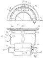
- the roof duct 10 shown overall in FIG. 1 shows an embodiment which is intended for a heating system with a condensate return facility is. From top to bottom, it consists of an attachment 12, a hood element 14, an outer tube section 16 on the outside of the roof, an outer tube section 18 on the inside of the roof, a branching element 20 and an exhaust pipe 22 which forms an inner tube in FIG. 1.
- the cover 12 comprising the shielding element (24, 36) and the condensate collecting element (28) in turn consists of three parts, a side wall element 24 that is the same in all embodiments, an optionally usable roof element 26 that is available in at least two variants, and a bottom wall that can be used in at least three variants 28.
- the condensate collecting element 28 preferably consists of a good heat-conducting material, in particular metal, preferably aluminum, in order to achieve good heating during operation so that the risk of icing is minimized.
- the attachment 12 can be heated electrically.
- a heating element 30 which is installed in the condensate collecting element 28, namely below a condensate collecting surface 32 on the top of the condensate collecting element 28.
- the condensate collecting surface 32 is located below an approximately cylindrical side wall 34 which tapers slightly downwards Sidewall element 24, so that condensate formed on the inside 36 of the sidewall 34 is collected by the condensate collecting surface 32.
- the condensate collecting element 28 is intended for a heating system which allows a condensate return.
- the condensate collected by the condensate collecting surface 32 is therefore returned to the exhaust pipe 22.
- the condensate collecting surface 32 is inclined conically (centrally to the outlet pipe axis 38). that the condensate flows radially inwards, in order then to be passed into the exhaust pipe interior through connecting channels in the form of inlet openings 40 in an upwardly projecting cylindrical collar 42 of the condensate collecting element 28.
- the collar 42 continues downward in a cylindrical section 44 which bears against the inside at the upper end of the exhaust pipe 22 and thus makes good thermal contact with the exhaust pipe 22.
- the collar 42 and section 44 are heated by the exhaust gas.
- the condensate collecting element 28 is provided with a downwardly projecting, essentially cylindrical collar 46, which primarily serves for mechanical stiffening.
- the shielding element 24 has at its lower end a cylindrical collar 48 with the same inside and outside diameter as the collar 42 on which it is placed.
- a total of four webs 50 extend from the collar 48, which are distributed over the circumference and first run radially outward from the collar 48, then at an incline upwards, in order then to be integrated with the side wall 34 for holding the side wall 34 on the collar 48.
- the side wall of the shielding element 34 has an inner diameter which significantly exceeds the inner diameter of the collar 48 as well as of the exhaust pipe 22.
- the lower edge 52 of the side wall 34 is located somewhat below the upper edge 54. This gives a total of four air flow openings 56, each of which is delimited by two adjacent webs 50 and the edges 52 and 54. Depending on the respective flow conditions, 56 fresh air can enter through these air flow openings for mixing with the exhaust gas or exhaust gas can flow through these air flow openings 56.
- the four webs 50 continue at the upper edge 58 of the side wall 35 and end in a retaining ring 60 for the respective roof element 26. In this way, four further air flow openings are formed, which represent exhaust gas outlet openings 62.
- the roof element 26 tapers conically downwards, so that condensate 64 formed on its underside, as indicated in FIG. 2, drips off at the tip of the cone, that is to say centrically to the axis 38.
- the inner surface 36 the condensate formed in the side wall 34 is discharged into the interior of the exhaust pipe 22 via the condensate collecting surface 32 and the inlet openings 40, the entire condensate flows back into the exhaust pipe 22.
- the assembly of the roof duct 10 shown overall in FIG. 1 is particularly simple since the individual parts essentially only need to be plugged together.
- the outer tube section 16 is connected to the hood element 14 via at least four upwardly projecting connecting webs 68 indicated in FIG. 1, which end in a retaining ring 70 (here by means of locking cams 72 on the outer circumference of the retaining ring 70, which engage in corresponding locking openings of the hood element 14 click into place).
- the roof duct 10 offers the possibility of fresh air supply to the heating system.
- the fresh air flow is symbolized by flow arrows 66.
- the air enters through an annular space between the lower end of the hood element 14 and the upper end of the outer tube section 16 past the connecting webs.
- the hood element 14 can be stiffened with a reinforcement ring 74, which can additionally be provided with stiffening angles 76 indicated in FIG. 1.
- the outer pipe section 16 can be formed with an apron 78 - the roof level is at least 15 cm below the apron 78.
- the section 16 is connected to the subsequent inner pipe section 18 on the roof side via a conventional plug connection.
- the section 16 in the region of the apron 78 can be formed with radially inwardly projecting centering tabs 82 which rest on the outer circumference of the exhaust pipe 22.
- the lower end of the outer tube section 18 on the roof side is also connected to a branch element 20 via a plug connection.
- the branching element 20 is sealed at the lower end of its central section 84 against the exhaust pipe 22 by a lip seal, not shown in FIG. 1.
- a corresponding lip seal can also be installed between the upper end of the central section 84 and the lower end of the outer pipe section 18.
- a branching pipe section 86 of the branching element 20 is connected in a manner not shown to a fresh air pipe leading to the heating system.
- a plurality of fastening screws 88 are provided, surrounded by an insulating ring 87, one of which is indicated in FIGS. 1 and 2. It passes through both an upper edge of the hood element 14 and a downwardly projecting web 90 of the condensate collecting element 28, the edge and / or web 90 being provided with a corresponding internal thread so that the fastening screws 88 can be screwed in for clamping engagement on the outer circumference of the exhaust pipe 22 .
- the roof element 26 is connected to the side wall part 24 via a type of bayonet connection.
- a type of bayonet connection for example, four bayonet recess 94 are formed on the outer circumference of the roof element 26, which in the mounting position according to FIGS. 2 and 3 are moved past the bayonet projections 96 of the retaining ring 60 projecting radially inwards until the outer edge of the roof element 26 on the upper sides (210 in FIG. 4 and 5) the webs 50 angled in this area rests. Subsequently, the roof element is rotated in the counterclockwise direction in FIG. 3 until a locking knob 98, which can be seen in FIG. 5 and protrudes upwards from the top of the respective web 50, snaps into the bayonet recess 94.
- the edge 94a of the bayonet recess 94 which is remote from the locking knob 94 is then located below the radially inwardly projecting bayonet projection 96 and abuts there against a projection 100 projecting downward from the bayonet projection 96.
- the roof element 26 is thus secured against turning back for reliable rigid attachment to the side wall element 24.
- FIGS. 4 and 5 show a variant of the attachment which is intended for heating systems without return of condensate.
- Components that correspond in function to those in the previous figures are provided with the same reference numbers, each increased by the number 100. Only the differences are dealt with below. For the rest, reference is made to the above statements relating to FIGS. 1 to 3.
- the attachment 112 comprising the shielding element and the condensate collecting element accordingly again consists of the three separate parts of the condensate collecting element 128, the side wall element 124 and the roof element 126.
- the side wall element 124 is identical in construction to the side wall element 24.
- the condensate collecting element 128 is designed radially to the outside for condensate drainage so that on the one hand the inlet openings 40 are omitted and on the other hand no conical beveling of the condensate collecting surface 132 is provided, but rather a continuously flat design in a horizontal plane (perpendicular to the axis 138 of the exhaust pipe 122).
- the condensate 164 dripping from the inside of the side wall 134 flows on, as indicated in FIG.
- the roof element 126 to be provided here in order to avoid condensate backflow is provided with an essentially annular drip edge 202 which is arranged centrally to the axis 138 and has a diameter such that condensate 164 dripping from it either directly or after striking the inside 136 of the side wall 124 strikes the condensate collecting surface 132 of the condensate collecting element 128.
- the roof element 126 can be formed with an inner, upwardly curved cone section 204, the outer edge of which merges into an oppositely curved cone ring section 206 in the region of the edge 202. With simple manufacture, this results in sufficient mechanical stability.
- An air inlet opening 67 (FIG. 2) or 167 (FIG. 4) is provided between the upper end of the hood element and the condensate collecting element for cooling the upper end of the hood element from fresh air.
- the already described bayonet connection is again provided for fastening the roof element 126 to the side wall element 124.
- the outline of the roof element 126 in its bayonet latching position is only indicated with an interrupted outline to clarify the structure. Accordingly, the webs 150 with through openings 208 can be seen in each case for the fastening screw designated 92 in FIG. 2 or for a pin 92 'integrally formed with the condensate collecting element 28 with a latching head (as indicated in FIG. 1).
- the bearing surface 210 is indicated on the upper web end for the peripheral edge of the roof element 126.
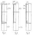
- a thermally insulated exhaust pipe section can be used, as shown in three exemplary embodiments in Figures 6 to 8 and is designated there with 212a, 212b, 212c.
- the generally metallic tube 214 is encased with a separate insulating layer 216a.
- the insulating layer 216b can also be foamed directly onto the pipe 214.
- a double-walled design is also possible from the inner tube 214 already mentioned and an outer tube 218.
- the pipe 214 can be stepped at both ends (Z-shaped cross-section) in accordance with the desired wall thickness of the insulating layer 216a or 216b or according to the desired radial dimension of the insulating annular space between tube 214 and outer tube 218.
- FIG. 4 shows the upper end of the exhaust pipe section 212c according to FIG. 8. It can also be seen that the cylindrical section 144 is adapted to the pipe shape.
- a continuous exhaust pipe with a thermally insulated section 212b and a non-insulated section 220 can also be used.
- a roof duct can be put together for a wide variety of circumstances.
- an attachment with roof element 26 according to FIGS. 2 and 3 or with roof element 126 according to FIGS. 4 and 5 can be used, or an attachment without a roof element.
- the condensate collecting element 28 is the condensate collecting element 28 according to FIG. 2 with or without heating element or the condensate collecting element 128 according to FIG Section of the exhaust pipe above the roof can be replaced by a thermally insulated exhaust pipe section according to Figures 6 to 8.
- the other elements of the kit in particular the shielding element 24 or 124, the hood element 14, the outer tube sections 16 and 18 and the branching element 20, are each unchanged.
Landscapes
- Engineering & Computer Science (AREA)
- General Engineering & Computer Science (AREA)
- Mechanical Engineering (AREA)
- Chemical & Material Sciences (AREA)
- Combustion & Propulsion (AREA)
- Thermal Sciences (AREA)
- Physics & Mathematics (AREA)
- Exhaust Silencers (AREA)
- Pipe Accessories (AREA)
- Incineration Of Waste (AREA)
- Instantaneous Water Boilers, Portable Hot-Water Supply Apparatuses, And Control Of Portable Hot-Water Supply Apparatuses (AREA)
- Heat Treatment Of Articles (AREA)
- Buildings Adapted To Withstand Abnormal External Influences (AREA)
- Chimneys And Flues (AREA)
Applications Claiming Priority (2)
| Application Number | Priority Date | Filing Date | Title |
|---|---|---|---|
| DE29606539U | 1996-04-10 | ||
| DE29606539U DE29606539U1 (de) | 1996-04-10 | 1996-04-10 | Aufsatz für ein Abgasrohr einer Heizungsanlage |
Publications (3)
| Publication Number | Publication Date |
|---|---|
| EP0801266A2 true EP0801266A2 (fr) | 1997-10-15 |
| EP0801266A3 EP0801266A3 (fr) | 1998-05-27 |
| EP0801266B1 EP0801266B1 (fr) | 2001-11-21 |
Family
ID=8022389
Family Applications (1)
| Application Number | Title | Priority Date | Filing Date |
|---|---|---|---|
| EP97201050A Expired - Lifetime EP0801266B1 (fr) | 1996-04-10 | 1997-04-08 | Chapeau pour cheminée d'une installation de chauffage |
Country Status (7)
| Country | Link |
|---|---|
| EP (1) | EP0801266B1 (fr) |
| AT (1) | ATE209318T1 (fr) |
| CZ (1) | CZ292376B6 (fr) |
| DE (2) | DE29606539U1 (fr) |
| DK (1) | DK0801266T3 (fr) |
| ES (1) | ES2163704T3 (fr) |
| PL (1) | PL184675B1 (fr) |
Cited By (4)
| Publication number | Priority date | Publication date | Assignee | Title |
|---|---|---|---|---|
| EP1039222A1 (fr) * | 1999-03-23 | 2000-09-27 | Klöber, Johannes | Traversée de toiture pour air d'admission et air d'échappement |
| NL1014235C2 (nl) * | 2000-01-31 | 2001-08-01 | Interactive Bouwprodukten B V | Rookgasafvoerstelsel. |
| US7682232B2 (en) * | 2006-09-16 | 2010-03-23 | Olympia Chimney Supply | Dripless chimney cap |
| EP2354694A3 (fr) * | 2010-02-08 | 2011-12-21 | Haven Limited | Système de protection contre le gel pour conduit de drainage de condensats |
Families Citing this family (4)
| Publication number | Priority date | Publication date | Assignee | Title |
|---|---|---|---|---|
| NL1012369C2 (nl) * | 1999-06-16 | 2000-12-19 | Interactive Bouwprodukten B V | Afscherminrichting. |
| US7354244B2 (en) | 2004-09-01 | 2008-04-08 | Aos Holding Company | Blower and method of conveying fluids |
| CN102410718A (zh) * | 2011-08-30 | 2012-04-11 | 宜兴市格兰特干燥浓缩设备有限公司 | 管束干燥机用冷凝水排出管道接口 |
| DE102021109583A1 (de) | 2021-04-16 | 2022-10-20 | Vaillant Gmbh | Abgasanlage für ein Heizgerät |
Family Cites Families (10)
| Publication number | Priority date | Publication date | Assignee | Title |
|---|---|---|---|---|
| AT367531B (de) * | 1979-09-25 | 1982-07-12 | Stranzinger Hermann | Vorrichtung zur ausnutzung der abgaswaerme einer feuerungsanlage, insbesondere einer oelheizung |
| US4306491A (en) * | 1979-11-26 | 1981-12-22 | Reardon Jr Charles A | Flue system for wood burning stoves |
| DE8801003U1 (de) * | 1988-01-28 | 1988-03-24 | Erlus Baustoffwerke Ag, 8301 Neufahrn | Kamin, insbesondere Fertigkamin |
| US4893608A (en) * | 1988-07-05 | 1990-01-16 | Coleman Heating & Air Conditioning Products, Inc. | Furnace roof jack with pivoting flashing plate |
| DE8816542U1 (de) * | 1988-07-08 | 1989-11-16 | Schiedel GmbH & Co, 8000 München | Schornsteinkopf für hinterlüftete mehrschalige Hausschornsteine |
| BE1004862A6 (nl) * | 1989-09-12 | 1993-02-09 | Vaillant Sa | Aansluitinrichting voor verwarmingsapparaten. |
| DE9002084U1 (de) * | 1990-02-22 | 1990-04-26 | Diehm Schornstein-Technik GmbH, 7710 Donaueschingen | Schornsteinaufsatz |
| NL9002786A (nl) * | 1990-12-17 | 1992-07-16 | Burgerhout Bv | Gecombineerde branderluchttoevoer en -verbrandingsgasafvoer. |
| NL9302032A (nl) * | 1993-11-24 | 1995-06-16 | Ubbink Nederland Bv | Uitmondingsconstructie voor gesloten gastoestellen. |
| NL9400659A (nl) * | 1994-04-25 | 1995-12-01 | Muelink & Grol Bv | Samenstel van luchttoevoer en/of verbrandingsgasafvoer voor aansluiting op een haard. |
-
1996
- 1996-04-10 DE DE29606539U patent/DE29606539U1/de not_active Expired - Lifetime
-
1997
- 1997-04-08 CZ CZ19971070A patent/CZ292376B6/cs not_active IP Right Cessation
- 1997-04-08 PL PL97319362A patent/PL184675B1/pl not_active IP Right Cessation
- 1997-04-08 AT AT97201050T patent/ATE209318T1/de not_active IP Right Cessation
- 1997-04-08 DK DK97201050T patent/DK0801266T3/da active
- 1997-04-08 ES ES97201050T patent/ES2163704T3/es not_active Expired - Lifetime
- 1997-04-08 EP EP97201050A patent/EP0801266B1/fr not_active Expired - Lifetime
- 1997-04-08 DE DE59705432T patent/DE59705432D1/de not_active Expired - Fee Related
Non-Patent Citations (1)
| Title |
|---|
| None |
Cited By (5)
| Publication number | Priority date | Publication date | Assignee | Title |
|---|---|---|---|---|
| EP1039222A1 (fr) * | 1999-03-23 | 2000-09-27 | Klöber, Johannes | Traversée de toiture pour air d'admission et air d'échappement |
| NL1014235C2 (nl) * | 2000-01-31 | 2001-08-01 | Interactive Bouwprodukten B V | Rookgasafvoerstelsel. |
| EP1122496A1 (fr) * | 2000-01-31 | 2001-08-08 | InterActive bouwprodukten B.V. | Dispositif pour l'évacuation des gaz de fumée |
| US7682232B2 (en) * | 2006-09-16 | 2010-03-23 | Olympia Chimney Supply | Dripless chimney cap |
| EP2354694A3 (fr) * | 2010-02-08 | 2011-12-21 | Haven Limited | Système de protection contre le gel pour conduit de drainage de condensats |
Also Published As
| Publication number | Publication date |
|---|---|
| ATE209318T1 (de) | 2001-12-15 |
| EP0801266A3 (fr) | 1998-05-27 |
| DK0801266T3 (da) | 2002-05-21 |
| PL319362A1 (en) | 1997-10-13 |
| DE59705432D1 (de) | 2002-01-03 |
| DE29606539U1 (de) | 1997-08-07 |
| PL184675B1 (pl) | 2002-11-29 |
| CZ292376B6 (cs) | 2003-09-17 |
| ES2163704T3 (es) | 2002-02-01 |
| CZ107097A3 (en) | 1997-10-15 |
| EP0801266B1 (fr) | 2001-11-21 |
Similar Documents
| Publication | Publication Date | Title |
|---|---|---|
| EP0801266A2 (fr) | Chapeau pour cheminée d'une installation de chauffage | |
| DE19754995C2 (de) | Hybridkühlturm | |
| DE19840594C2 (de) | Flachdach-Entlüftungs-Vorrichtung | |
| EP0257636B1 (fr) | Tête pour cheminées ventilées multi-couches | |
| DE3045662A1 (de) | Waermeabsorber zum entziehen von waermeenergie aus der umgebung und/oder aus der sonnenstrahlung fuer den betrieb von heizungsanlagen | |
| DE7724113U1 (de) | Sonnenenergie-kollektor mit ein- und auslassleitung | |
| EP0495805B1 (fr) | Ventilation faitiere | |
| DE2701383C3 (de) | Lüftungsvorrichtung für mit Dacheindeckungsplatten eingedeckte Dächer | |
| DE2841570A1 (de) | Schornstein | |
| DE2032249C2 (de) | Flachdachentlüfter aus Kunststoff | |
| DE69500864T2 (de) | Anordnung eines Luftzufuhrrohres und/oder eines Rauchgas-Abfuhrrohres für die Verbindung zu einem Ofen | |
| DE3202509A1 (de) | Vorrichtung zur unterdrueckung von schwitzwasserbildung an dachfolien | |
| EP0125673A1 (fr) | Echangeur de chaleur | |
| EP0296125B1 (fr) | Elément de couverture de cheminée et chapeau associé | |
| EP0349802A1 (fr) | Chapeau de cheminée pour cheminées de maison ventilées multicouches | |
| DE2452706A1 (de) | Schachtabdeckung | |
| DE8904865U1 (de) | Abgasführung eines brennerbeheizten Gerätes | |
| DE29715418U1 (de) | Vertikale Durchführung eines Abgasrohres | |
| DE2922652A1 (de) | Dacheindeckungsanordnung | |
| DE3014547C2 (fr) | ||
| EP0073843A1 (fr) | Couvertures de toit de captage d'énergie de l'environnement | |
| DE4320300A1 (de) | Sonderabfallbehälter | |
| DE3219979C2 (de) | Beheizbarer Dachüberhang | |
| DE2402439A1 (de) | Vorrichtung zum aufschmelzen des eises und zur verhinderung der eisbildung im bereich einer dachkante | |
| AT403180B (de) | Abdeckelement |
Legal Events
| Date | Code | Title | Description |
|---|---|---|---|
| PUAI | Public reference made under article 153(3) epc to a published international application that has entered the european phase |
Free format text: ORIGINAL CODE: 0009012 |
|
| AK | Designated contracting states |
Kind code of ref document: A2 Designated state(s): AT BE CH DE DK ES FR GB IT LI LU NL |
|
| PUAL | Search report despatched |
Free format text: ORIGINAL CODE: 0009013 |
|
| AK | Designated contracting states |
Kind code of ref document: A3 Designated state(s): AT BE CH DE DK ES FR GB IT LI LU NL |
|
| 17P | Request for examination filed |
Effective date: 19981126 |
|
| 17Q | First examination report despatched |
Effective date: 19990115 |
|
| GRAG | Despatch of communication of intention to grant |
Free format text: ORIGINAL CODE: EPIDOS AGRA |
|
| GRAG | Despatch of communication of intention to grant |
Free format text: ORIGINAL CODE: EPIDOS AGRA |
|
| GRAH | Despatch of communication of intention to grant a patent |
Free format text: ORIGINAL CODE: EPIDOS IGRA |
|
| GRAH | Despatch of communication of intention to grant a patent |
Free format text: ORIGINAL CODE: EPIDOS IGRA |
|
| 18D | Application deemed to be withdrawn |
Effective date: 20001124 |
|
| GRAA | (expected) grant |
Free format text: ORIGINAL CODE: 0009210 |
|
| D18D | Application deemed to be withdrawn (deleted) | ||
| AK | Designated contracting states |
Kind code of ref document: B1 Designated state(s): AT BE CH DE DK ES FR GB IT LI LU NL |
|
| REF | Corresponds to: |
Ref document number: 209318 Country of ref document: AT Date of ref document: 20011215 Kind code of ref document: T |
|
| REG | Reference to a national code |
Ref country code: CH Ref legal event code: NV Representative=s name: BUGNION S.A. Ref country code: CH Ref legal event code: EP |
|
| REG | Reference to a national code |
Ref country code: GB Ref legal event code: IF02 |
|
| REF | Corresponds to: |
Ref document number: 59705432 Country of ref document: DE Date of ref document: 20020103 |
|
| REG | Reference to a national code |
Ref country code: ES Ref legal event code: FG2A Ref document number: 2163704 Country of ref document: ES Kind code of ref document: T3 |
|
| ET | Fr: translation filed | ||
| GBT | Gb: translation of ep patent filed (gb section 77(6)(a)/1977) |
Effective date: 20020118 |
|
| PGFP | Annual fee paid to national office [announced via postgrant information from national office to epo] |
Ref country code: ES Payment date: 20020424 Year of fee payment: 6 |
|
| REG | Reference to a national code |
Ref country code: DK Ref legal event code: T3 |
|
| PLBE | No opposition filed within time limit |
Free format text: ORIGINAL CODE: 0009261 |
|
| STAA | Information on the status of an ep patent application or granted ep patent |
Free format text: STATUS: NO OPPOSITION FILED WITHIN TIME LIMIT |
|
| 26N | No opposition filed | ||
| PG25 | Lapsed in a contracting state [announced via postgrant information from national office to epo] |
Ref country code: ES Free format text: LAPSE BECAUSE OF NON-PAYMENT OF DUE FEES Effective date: 20030409 |
|
| REG | Reference to a national code |
Ref country code: ES Ref legal event code: FD2A Effective date: 20030409 |
|
| PGFP | Annual fee paid to national office [announced via postgrant information from national office to epo] |
Ref country code: DE Payment date: 20060426 Year of fee payment: 10 Ref country code: AT Payment date: 20060426 Year of fee payment: 10 |
|
| PGFP | Annual fee paid to national office [announced via postgrant information from national office to epo] |
Ref country code: LU Payment date: 20060427 Year of fee payment: 10 Ref country code: FR Payment date: 20060427 Year of fee payment: 10 Ref country code: DK Payment date: 20060427 Year of fee payment: 10 Ref country code: CH Payment date: 20060427 Year of fee payment: 10 Ref country code: BE Payment date: 20060427 Year of fee payment: 10 |
|
| PGFP | Annual fee paid to national office [announced via postgrant information from national office to epo] |
Ref country code: NL Payment date: 20060429 Year of fee payment: 10 |
|
| PGFP | Annual fee paid to national office [announced via postgrant information from national office to epo] |
Ref country code: IT Payment date: 20060430 Year of fee payment: 10 |
|
| REG | Reference to a national code |
Ref country code: FR Ref legal event code: CD |
|
| REG | Reference to a national code |
Ref country code: DK Ref legal event code: EBP |
|
| REG | Reference to a national code |
Ref country code: CH Ref legal event code: PL |
|
| GBPC | Gb: european patent ceased through non-payment of renewal fee |
Effective date: 20070408 |
|
| BERE | Be: lapsed |
Owner name: *INTERACTIVE HOLDING B.V. Effective date: 20070430 |
|
| NLV4 | Nl: lapsed or anulled due to non-payment of the annual fee |
Effective date: 20071101 |
|
| PG25 | Lapsed in a contracting state [announced via postgrant information from national office to epo] |
Ref country code: NL Free format text: LAPSE BECAUSE OF NON-PAYMENT OF DUE FEES Effective date: 20071101 Ref country code: DE Free format text: LAPSE BECAUSE OF NON-PAYMENT OF DUE FEES Effective date: 20071101 |
|
| PG25 | Lapsed in a contracting state [announced via postgrant information from national office to epo] |
Ref country code: CH Free format text: LAPSE BECAUSE OF NON-PAYMENT OF DUE FEES Effective date: 20070430 Ref country code: LI Free format text: LAPSE BECAUSE OF NON-PAYMENT OF DUE FEES Effective date: 20070430 Ref country code: AT Free format text: LAPSE BECAUSE OF NON-PAYMENT OF DUE FEES Effective date: 20070408 |
|
| PG25 | Lapsed in a contracting state [announced via postgrant information from national office to epo] |
Ref country code: BE Free format text: LAPSE BECAUSE OF NON-PAYMENT OF DUE FEES Effective date: 20070430 |
|
| PG25 | Lapsed in a contracting state [announced via postgrant information from national office to epo] |
Ref country code: GB Free format text: LAPSE BECAUSE OF NON-PAYMENT OF DUE FEES Effective date: 20070408 Ref country code: DK Free format text: LAPSE BECAUSE OF NON-PAYMENT OF DUE FEES Effective date: 20070430 |
|
| PG25 | Lapsed in a contracting state [announced via postgrant information from national office to epo] |
Ref country code: FR Free format text: LAPSE BECAUSE OF NON-PAYMENT OF DUE FEES Effective date: 20070430 |
|
| PGFP | Annual fee paid to national office [announced via postgrant information from national office to epo] |
Ref country code: GB Payment date: 20060328 Year of fee payment: 10 |
|
| PG25 | Lapsed in a contracting state [announced via postgrant information from national office to epo] |
Ref country code: LU Free format text: LAPSE BECAUSE OF NON-PAYMENT OF DUE FEES Effective date: 20070408 |
|
| PG25 | Lapsed in a contracting state [announced via postgrant information from national office to epo] |
Ref country code: IT Free format text: LAPSE BECAUSE OF NON-PAYMENT OF DUE FEES Effective date: 20070408 |