EP0801430A1 - Piles alcalines et méthode de fabrication d'électrodes au nickel pour celles-ci - Google Patents
Piles alcalines et méthode de fabrication d'électrodes au nickel pour celles-ci Download PDFInfo
- Publication number
- EP0801430A1 EP0801430A1 EP96119119A EP96119119A EP0801430A1 EP 0801430 A1 EP0801430 A1 EP 0801430A1 EP 96119119 A EP96119119 A EP 96119119A EP 96119119 A EP96119119 A EP 96119119A EP 0801430 A1 EP0801430 A1 EP 0801430A1
- Authority
- EP
- European Patent Office
- Prior art keywords
- electroconductive
- electrode
- active material
- substrates
- nickel
- Prior art date
- Legal status (The legal status is an assumption and is not a legal conclusion. Google has not performed a legal analysis and makes no representation as to the accuracy of the status listed.)
- Granted
Links
Images

Classifications
-
- H—ELECTRICITY
- H01—ELECTRIC ELEMENTS
- H01M—PROCESSES OR MEANS, e.g. BATTERIES, FOR THE DIRECT CONVERSION OF CHEMICAL ENERGY INTO ELECTRICAL ENERGY
- H01M4/00—Electrodes
- H01M4/02—Electrodes composed of, or comprising, active material
- H01M4/64—Carriers or collectors
- H01M4/70—Carriers or collectors characterised by shape or form
- H01M4/72—Grids
- H01M4/74—Meshes or woven material; Expanded metal
- H01M4/742—Meshes or woven material; Expanded metal perforated material
-
- H—ELECTRICITY
- H01—ELECTRIC ELEMENTS
- H01M—PROCESSES OR MEANS, e.g. BATTERIES, FOR THE DIRECT CONVERSION OF CHEMICAL ENERGY INTO ELECTRICAL ENERGY
- H01M4/00—Electrodes
- H01M4/02—Electrodes composed of, or comprising, active material
- H01M4/24—Electrodes for alkaline accumulators
-
- H—ELECTRICITY
- H01—ELECTRIC ELEMENTS
- H01M—PROCESSES OR MEANS, e.g. BATTERIES, FOR THE DIRECT CONVERSION OF CHEMICAL ENERGY INTO ELECTRICAL ENERGY
- H01M4/00—Electrodes
- H01M4/02—Electrodes composed of, or comprising, active material
- H01M4/24—Electrodes for alkaline accumulators
- H01M4/26—Processes of manufacture
-
- H—ELECTRICITY
- H01—ELECTRIC ELEMENTS
- H01M—PROCESSES OR MEANS, e.g. BATTERIES, FOR THE DIRECT CONVERSION OF CHEMICAL ENERGY INTO ELECTRICAL ENERGY
- H01M4/00—Electrodes
- H01M4/02—Electrodes composed of, or comprising, active material
- H01M4/24—Electrodes for alkaline accumulators
- H01M4/32—Nickel oxide or hydroxide electrodes
-
- H—ELECTRICITY
- H01—ELECTRIC ELEMENTS
- H01M—PROCESSES OR MEANS, e.g. BATTERIES, FOR THE DIRECT CONVERSION OF CHEMICAL ENERGY INTO ELECTRICAL ENERGY
- H01M4/00—Electrodes
- H01M4/02—Electrodes composed of, or comprising, active material
- H01M4/64—Carriers or collectors
-
- Y—GENERAL TAGGING OF NEW TECHNOLOGICAL DEVELOPMENTS; GENERAL TAGGING OF CROSS-SECTIONAL TECHNOLOGIES SPANNING OVER SEVERAL SECTIONS OF THE IPC; TECHNICAL SUBJECTS COVERED BY FORMER USPC CROSS-REFERENCE ART COLLECTIONS [XRACs] AND DIGESTS
- Y02—TECHNOLOGIES OR APPLICATIONS FOR MITIGATION OR ADAPTATION AGAINST CLIMATE CHANGE
- Y02E—REDUCTION OF GREENHOUSE GAS [GHG] EMISSIONS, RELATED TO ENERGY GENERATION, TRANSMISSION OR DISTRIBUTION
- Y02E60/00—Enabling technologies; Technologies with a potential or indirect contribution to GHG emissions mitigation
- Y02E60/10—Energy storage using batteries
Definitions
- the present invention relates to alkaline storage batteries and a method of making nickel electrodes for the said storage batteries.
- foamed metal type electrodes having higher capacity density than sintered type electrodes have spread much as the nickel electrodes of alkaline storage batteries.
- the foamed metal type electrodes have the defects that the foamed metal as a substrate is expensive and remarkable improvement of capacity density is difficult owing to the structure of the foamed metal.
- pasted type electrodes comprising an inexpensive planar porous body as an electroconductive substrate coated with a pasted active material have been developed as a substitute for the foamed metal type electrodes.
- the planar electroconductive substrates investigated as the pasted type electrodes are, for example, expanded metals, screens and punching metals.
- Binders to be added to the active material paste for improving the holding of the active material include, for example, polyvinyl alcohol, carboxymethylcellulose, polyethylene, polyvinyl chloride, styrene-butadiene rubbers and fluororesins.
- the problems of the pasted type electrodes are insufficient contact of the active material with the electroconductive substrate and insufficient electrical conductivity because the electroconductive substrate is a planar porous body and not of the three-dimensional structure as of the foamed metal type.
- JP-A-56-22049 proposes to add a graphite powder, a nickel powder or a fiber thereof to the active material.
- these conductive agents are added in such an amount as being able to obtain a capacity density equal to that obtained by using the foamed metal electrodes, the conductivity of the whole electrodes is insufficient, and active material utilization and discharge voltage characteristics are inferior.
- JP-A-6-314567 proposes to use an electroconductive substrate having a solid form, but this electroconductive substrate is insufficient in the contact between the active material and the electroconductive substrate as compared with the electroconductive substrates having three-dimensional structure such as the foamed metal. Therefore, unless conductive agents such as a graphite powder and a nickel powder are added, active material utilization is low and the electrodes using such electroconductive substrates are still inferior in discharge voltage characteristics and charge-discharge cycle life. Thus, such pasted electrodes have not yet been widespread.
- the electroconductive substrate is planar, the contact between the active material and the electroconductive substrate is insufficient.
- the thickness of the active material layer coated on the electroconductive substrate is more than 300 ⁇ m, the conductivity of the active material and the electroconductive substrate in the direction of thickness becomes insufficient. This is a main cause for the inferior active material utilization and discharge voltage characteristics as compared with those of foamed metal type electrodes.
- Nickel hydroxide which is an active material of nickel electrode produces nickel oxyhydroxide of low density in an increased amount when the amount of overcharge increases, and this causes swelling of the plates.
- the electrolyte when used in a small amount with a view that the gas generated from a positive plate at the time of charging is absorbed by a negative plate as in the case of sealed batteries, the nickel plate absorbs the electrolyte in an excess amount than needed with repetition of charging and discharging due to acceleration of swelling. This causes shortage of the electrolyte in the separator, which gives rise to the problems of deterioration in both the discharge voltage and the capacity.
- Another problem in the pasted type electrode is that if the swelling of the plate increases, adhesion between the electroconductive substrate and the active material layer lowers, resulting in peeling off of the active material layer from the electroconductive substrate.
- the main object of the present invention is to solve the above problems and improve the discharge voltage characteristics and the charge-discharge cycle life by increasing the active material utilization in pasted type nickel electrodes.
- the nickel electrode of the alkaline storage batteries according to the present invention has a structure comprising a plurality of active material layers each having a thickness of 20-250 ⁇ m and a plurality of electroconductive substrates each having a thickness of 5-60 ⁇ m which are alternately laminated into an integral form, and the electroconductive substrates are electrically and mechanically connected with each other through a part of the respective electroconductive substrates.
- the total number of the active material layers and the electroconductive substrates is preferably 8 - 12.
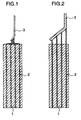
- the nickel electrode of the present invention can be obtained by laminating a plurality of electrode leaves each of which comprises the electroconductive substrate coated with the active material paste on one side or both sides with utilizing the tackiness of the paste before drying, thereby to integrate the active material layer and the electroconductive substrate, and, then, pressing the laminate to increase the adhesion between the electroconductive substrate and the active material layer with adjusting the thickness of the plate as shown in Fig. 1.
- the electroconductive substrates 2 differing in the width from each other are coated with an active material paste 1 at a constant width, and prepared electrode leaves.
- the electrode leaves are laminated with ends of the electrode leaves being assembled evenly and flat.
- the portion of the electroconductive substrates which is not coated with the active material is welded with, for example a nickel ribbon 3 or a nickel sheath to form a collector, and, thus, uniform collection of current is possible (Embodiment 1).
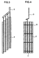
- the electroconductive substrates 2 having the same width are coated with an active material paste 1 at a constant width.
- the electrode leaves are laminated with ends of the electrode leaves being assembled in a stepped manner.
- the portion of the electroconductive substrates which is not coated with the active material is welded with, for example a nickel ribbon 3 or a nickel sheath to form a collector, and, thus, uniform collection of current is possible (Embodiment 2)
- Electrode leaves which include at least one electrode leaf made using an electroconductive substrate having at one end a portion coated with no active material, and a conductive paste or conductor 8 is filled into the holes to connect the electroconductive substrates with each other, and, thus, uniform collection of current is possible (Embodiment 3).
- Embodiments 1 and 2 More uniform collection of current becomes possible by combining Embodiments 1 and 2 with Embodiment 3.
- the thickness of the electroconductive substrates less than 5 ⁇ m is not preferred because strength of the electroconductive substrate is low and the electroconductive substrates are broken when they are pressed after coated with the active material.
- it is more than 60 ⁇ m, the occupying volume increases and improvement of capacity density as a battery cannot be expected.
- the electroconductive substrates there may be used any of nickel foils, synthetic resin films coated with nickel on both sides and perforated steel sheets plated with nickel.
- the thickness of the nickel layer is preferably 2-5 ⁇ m, and if it is less than 2 ⁇ m, a sufficient conductivity cannot be secured and if it is more than 5 ⁇ m, the capacity density decreases.
- synthetic resin films it is necessary to use those which are stable in an aqueous alkali solution such as, for example, polypropylene, polyethylene, nylon and polytetrafluoroethylene.
- the active material and binders in which the active material is dispersed have no special limitation, and those known to one skilled in the art can be used.
- the conductive agents which may be added to the active material layer have no special limitation but such as metallic cobalt or cobalt oxide is preferred.
- the conductive agent to be filled into the fine holes in the Embodiment 3 are also not limited, but a conductive paste mainly composed of Ni or a conductor of Ni pin is preferred.
- the electrolyte in the plate may be ununiformly distributed. Therefore, by making fine holes of 0.1-1 mm in diameter through the electroconductive substrates at an opening percentage of 10-60%, the electrolyte can be uniformly distributed in the plate. However, if the opening percentage exceeds 60%, strength of the electroconductive substrates lowers and, hence, there is a high possibility of the electroconductive substrates being broken when a cylindrical battery is fabricated.
- Fig. 1 is a schematic sectional view of nickel plate A in the example of the present invention.
- Fig. 2 is a sectional view which schematically shows the electrical connection of electrode leaves of the present invention.
- Fig. 3 is a sectional view which schematically shows the electrical connection of electrode leaves of the present invention.
- Fig. 4 is a sectional view which schematically shows the electrical connection of electrode leaves of the present invention.
- Fig. 5 is a schematic sectional view of battery B in the example of the present invention.
- the nickel electrode of alkaline storage battery has a structure comprising a plurality of active material layers each having a thickness of 20-250 ⁇ m and a plurality of electroconductive substrates each having a thickness of 5-60 ⁇ m which are alternately laminated and integrated, the electroconductive substrates being electrically and mechanically connected with each other through a part of the respective electroconductive substrates.
- the invention described in claim 6 given hereinafter specifies a method for making a nickel electrode.
- the thickness of each of the active material layers after making a plate is 250 ⁇ m or less, the conductivity can be sufficiently secured by the addition of conductive agents such as metallic cobalt and cobalt oxide. Therefore, the nickel electrode is improved in active material utilization and discharge voltage characteristics as compared with the conventional pasted type electrodes.
- the constituting material of this thicker electroconductive substrate may be the same or different from that of other electroconductive substrates.
- the electrode leaf made using the thicker electroconductive substrate may be placed at an optional position among a plurality of the electrode leaves, but preferably is placed around the center of the electrode thickness.
- the thickness of the thicker electroconductive substrate is preferably 3-10 times that of other electroconductive substrates, and preferably 5-10 times when only one thicker electroconductive substrate is used.
- Nickel foils having holes of 0.5 mm in diameter at an opening percentage of 20% and having a thickness of 15 ⁇ m and a width of 35.5, 36.0, 36.5 and 37.0 mm were used as the electroconductive substrates. Both sides of the electroconductive substrates were coated at a thickness of 200 ⁇ m with an active material paste of 20% in water content which was prepared by kneading 100 parts by weight of commercially available nickel hydroxide powder, 8 parts by weight of cobalt oxide powder, 15 parts by weight of 3 wt% aqueous solution of carboxymethylcellulose, and 5 parts by weight of polytetrafluoroethylene dispersion (solid content 48%).
- the width of active material paste (1) coated was 35 mm, and a portion which was not coated with the active material was provided at one end of each electroconductive substrate (2).
- the thus coated electroconductive substrates were laminated with the lower ends coated with the active material being assembled evenly and flat as shown in FIG. 1.
- the laminate was dried at 90°C, and, then was pressed so that the total thickness of the plate reached 0.7 mm, thereby to bond the respective layers.
- an Ni ribbon of 4 mm wide was welded to the portion of each electroconductive substrate which was not coated with the active material to form a current collector (3).
- the thus obtained plate was called "plate A".
- FIG. 1 shows a sectional view of this plate A.
- Both sides of polypropylene films having holes of 0.5 mm in diameter at an opening percentage of 15% and having a thickness of 10 ⁇ m and a width of 35.5, 36.0, 36.5 and 37.0 mm were coated with metallic nickel by vapor deposition to obtain an electroconductive substrate.
- the thickness of the nickel layer is 2.5 ⁇ m.
- plate B was made in the same manner as in making the plate A.
- a polypropylene film was used, but any resin films of polyethylene, nylon, polytetrafluoroethylene, etc. which are stable in an alkali solution can also be used.
- the synthetic resin film can be coated with nickel by electroplating or chemical plating in place of the vapor deposition to obtain the similar electroconductive substrate.
- Plates C and D were made in the same manner as in EXAMPLES 1 and 2, except for using a nickel-plated punching metal of 36.0 mm width in place of the nickel foil and nickel-coated polypropylene film of 36.0 mm width. That is, the plates C and D corresponded to the plates A and B in which a thicker nickel-plated iron punching metal was inserted at the central part, respectively.
- the nickel-plated punching metal used had holes of 1 mm in diameter at an opening percentage of 50% and had a thickness of 50 ⁇ m and a width of 36.0 mm.
- a conductive paste prepared by kneading 70 parts of nickel powder and 30 parts of a 10% aqueous carboxymethylcellulose solution was filled into the holes to make plate E.
- a conductive paste 8 a mixture of Ni powder and epoxy resin may be used, and, furthermore, an Ni pin which is a conductor may also be used.
- batteries were fabricated using the plate B, the plate D and the plate E and evaluated on their characteristics.
- This pasted type hydrogen-storing alloy electrode was cut to 35 mm width and 120 mm length, to which a lead plate was attached by spot welding.
- This negative plate 6 and the plate B, the plate D or the plate E between which a polypropylene nonwoven fabric separator subjected to hydrophilic treatment was inserted were rolled into a spiral and this was contained in case 7 to form a sealed nickel ⁇ hydrogen storage battery, which was filled with an electrolyte prepared by dissolving 30 g/l of lithium hydroxide in an aqueous potassium hydroxide solution having a specific gravity of 1.30.
- 4/5A type batteries B, D, and E of 1400 mAh in nominal capacity corresponding to the plates b, d and e, respectively were fabricated.
- FIG. 5 shows a sectional view of battery B.
- battery F was fabricated in the same manner as above, using a nickel electrode made by coating both sides of a punching metal having a thickness of 70 ⁇ and having holes of 2 mm in diameter at an opening percentage of 50% as an electroconductive substrate with the same active material as in EXAMPLE 1 at a thickness of 1500 ⁇ m and pressing it to a total thickness of 0.7 mm.
- the batteries B, D, E and F were subjected to the conventional formation and, then, evaluated on discharge characteristics. They were charged at 0.2 CmA for 6 hours and, then, discharged at 0.2, 1, and 3 CmA to 1.0 V. The results are shown in TABLE 1.
- batteries B, D and E were superior to battery F in active material utilization and discharge voltage. Especially, the discharge voltage at a high rate discharge was high in batteries D and E.
- the nickel electrode of the alkaline storage batteries according to the present invention has the structure comprising a plurality of active material layers each having a thickness of 20-250 ⁇ m and a plurality of electroconductive substrates each having a thickness of 5-60 ⁇ m which are alternated with each other and integrated, and the electroconductive substrates are electrically and mechanically connected through a part of the respective electroconductive substrates. Therefore, pasted type nickel electrodes excellent in active material utilization, discharge voltage characteristics and charge-discharge repetition characteristics are obtained.
Landscapes
- Chemical & Material Sciences (AREA)
- Chemical Kinetics & Catalysis (AREA)
- Electrochemistry (AREA)
- General Chemical & Material Sciences (AREA)
- Engineering & Computer Science (AREA)
- Manufacturing & Machinery (AREA)
- Battery Electrode And Active Subsutance (AREA)
- Cell Electrode Carriers And Collectors (AREA)
Applications Claiming Priority (3)
| Application Number | Priority Date | Filing Date | Title |
|---|---|---|---|
| JP96492/96 | 1996-04-18 | ||
| JP09649296A JP3527586B2 (ja) | 1996-04-18 | 1996-04-18 | アルカリ蓄電池用ニッケル電極の製造法 |
| JP9649296 | 1996-04-18 |
Publications (2)
| Publication Number | Publication Date |
|---|---|
| EP0801430A1 true EP0801430A1 (fr) | 1997-10-15 |
| EP0801430B1 EP0801430B1 (fr) | 2001-05-09 |
Family
ID=14166590
Family Applications (1)
| Application Number | Title | Priority Date | Filing Date |
|---|---|---|---|
| EP96119119A Expired - Lifetime EP0801430B1 (fr) | 1996-04-18 | 1996-11-28 | Piles alcalines et méthode de fabrication d'électrodes au nickel pour celles-ci |
Country Status (4)
| Country | Link |
|---|---|
| US (1) | US5744263A (fr) |
| EP (1) | EP0801430B1 (fr) |
| JP (1) | JP3527586B2 (fr) |
| DE (1) | DE69612733T2 (fr) |
Cited By (1)
| Publication number | Priority date | Publication date | Assignee | Title |
|---|---|---|---|---|
| WO2000030192A1 (fr) * | 1998-11-13 | 2000-05-25 | Moltech Power Systems, Inc. | Electrode positive recouverte d'une pate et procede de production associe |
Families Citing this family (11)
| Publication number | Priority date | Publication date | Assignee | Title |
|---|---|---|---|---|
| JP3191752B2 (ja) | 1996-12-26 | 2001-07-23 | 松下電器産業株式会社 | ニッケル−水素二次電池およびその電極の製造方法 |
| US6221527B1 (en) * | 1998-12-01 | 2001-04-24 | Eveready Battery Company, Inc. | Electrode for an electrochemical cell including ribbons |
| JP2001283901A (ja) * | 2000-03-31 | 2001-10-12 | Sanyo Electric Co Ltd | アルカリ蓄電池 |
| KR20020035771A (ko) * | 2000-11-07 | 2002-05-15 | 마츠시타 덴끼 산교 가부시키가이샤 | 배터리용 전극을 제조하는 방법 |
| JP2005038730A (ja) * | 2003-07-16 | 2005-02-10 | Yuasa Corp | 非焼結式ニッケル電極およびアルカリ蓄電池 |
| JP2006134891A (ja) * | 2004-09-09 | 2006-05-25 | Mitsui Mining & Smelting Co Ltd | 非水電解液二次電池用負極 |
| JP2012129477A (ja) * | 2010-12-17 | 2012-07-05 | Ud Trucks Corp | 蓄電セル |
| JP6058987B2 (ja) * | 2012-11-29 | 2017-01-11 | 京セラ株式会社 | 二次電池 |
| JP6075638B2 (ja) * | 2013-09-30 | 2017-02-08 | 株式会社Gsユアサ | 電池 |
| CN110729457A (zh) * | 2019-10-22 | 2020-01-24 | 益阳科力远电池有限责任公司 | 镍电池正极片的制作方法 |
| JPWO2023195233A1 (fr) * | 2022-04-07 | 2023-10-12 |
Citations (2)
| Publication number | Priority date | Publication date | Assignee | Title |
|---|---|---|---|---|
| US4663256A (en) * | 1985-10-25 | 1987-05-05 | General Motors Corporation | Nonsintered nickel electrode |
| EP0420669A2 (fr) * | 1989-09-29 | 1991-04-03 | Kabushiki Kaisha Toshiba | Cellule secondaire à nickel-hydrure métallique |
Family Cites Families (3)
| Publication number | Priority date | Publication date | Assignee | Title |
|---|---|---|---|---|
| JPS6459770A (en) * | 1987-08-31 | 1989-03-07 | Hitachi Chemical Co Ltd | Secondary battery |
| JPH05205746A (ja) * | 1992-01-24 | 1993-08-13 | Matsushita Electric Ind Co Ltd | 電極用集電体とその製造法、及びそれを用いた水素吸蔵電極とニッケル−水素蓄電池 |
| JPH0850893A (ja) * | 1994-08-04 | 1996-02-20 | Ricoh Co Ltd | 二次電池用電極 |
-
1996
- 1996-04-18 JP JP09649296A patent/JP3527586B2/ja not_active Expired - Lifetime
- 1996-11-22 US US08/754,135 patent/US5744263A/en not_active Expired - Lifetime
- 1996-11-28 DE DE69612733T patent/DE69612733T2/de not_active Expired - Fee Related
- 1996-11-28 EP EP96119119A patent/EP0801430B1/fr not_active Expired - Lifetime
Patent Citations (2)
| Publication number | Priority date | Publication date | Assignee | Title |
|---|---|---|---|---|
| US4663256A (en) * | 1985-10-25 | 1987-05-05 | General Motors Corporation | Nonsintered nickel electrode |
| EP0420669A2 (fr) * | 1989-09-29 | 1991-04-03 | Kabushiki Kaisha Toshiba | Cellule secondaire à nickel-hydrure métallique |
Cited By (3)
| Publication number | Priority date | Publication date | Assignee | Title |
|---|---|---|---|---|
| WO2000030192A1 (fr) * | 1998-11-13 | 2000-05-25 | Moltech Power Systems, Inc. | Electrode positive recouverte d'une pate et procede de production associe |
| US6436575B1 (en) | 1998-11-13 | 2002-08-20 | Moltech Power Systems, Inc. | Pasted positive electrode and process for its production |
| US6489058B1 (en) | 1998-11-13 | 2002-12-03 | Moltech Power Systems | Pasted positive electrode and process for its production |
Also Published As
| Publication number | Publication date |
|---|---|
| DE69612733T2 (de) | 2002-04-25 |
| DE69612733D1 (de) | 2001-06-13 |
| JPH09283133A (ja) | 1997-10-31 |
| US5744263A (en) | 1998-04-28 |
| JP3527586B2 (ja) | 2004-05-17 |
| EP0801430B1 (fr) | 2001-05-09 |
Similar Documents
| Publication | Publication Date | Title |
|---|---|---|
| US5585142A (en) | Method for preparing conductive electrochemically active material | |
| EP0409616A1 (fr) | Disposition enroulée d'électrode pour cellule électrochimique | |
| CN101641815A (zh) | 电池电极和包括此类电极的电池 | |
| EP0801430B1 (fr) | Piles alcalines et méthode de fabrication d'électrodes au nickel pour celles-ci | |
| JP3260972B2 (ja) | 水素吸蔵合金電極および同電極を用いた密閉型ニッケル−水素蓄電池 | |
| JP4429569B2 (ja) | ニッケル水素蓄電池 | |
| US6309775B1 (en) | Prismatic electrochemical cell | |
| US6468687B1 (en) | Alkaline storage battery with reinforced separators | |
| CN1211089A (zh) | 碱性蓄电池 | |
| JPH11185767A (ja) | ニッケル水素二次電池及び電極の製造方法 | |
| US6653023B1 (en) | Rectangular battery | |
| JP2002343366A (ja) | アルカリ蓄電池用極板およびそれを用いたアルカリ蓄電池 | |
| JP3209071B2 (ja) | アルカリ蓄電池 | |
| KR100943751B1 (ko) | 니켈-수소 2차전지 | |
| JP3094033B2 (ja) | ニッケル水素二次電池 | |
| JP2002100396A (ja) | 円筒形アルカリ二次電池 | |
| US5955216A (en) | Sealed alkaline storage battery | |
| JP2001006688A (ja) | ニッケル・水素二次電池 | |
| JP4413294B2 (ja) | アルカリ二次電池 | |
| EP0746049A1 (fr) | Accumulateur alcalin à électrodes contenant des feuilles poinçonnées comme substrat | |
| JPH103928A (ja) | ニッケル−水素二次電池 | |
| JP2001307764A (ja) | アルカリ二次電池及びアルカリ二次電池の製造方法 | |
| JP2001052732A (ja) | 円筒形アルカリ二次電池 | |
| JPS63259963A (ja) | 密閉形アルカリ蓄電池 | |
| JP2000277122A (ja) | 円筒形電池 |
Legal Events
| Date | Code | Title | Description |
|---|---|---|---|
| PUAI | Public reference made under article 153(3) epc to a published international application that has entered the european phase |
Free format text: ORIGINAL CODE: 0009012 |
|
| 17P | Request for examination filed |
Effective date: 19961128 |
|
| AK | Designated contracting states |
Kind code of ref document: A1 Designated state(s): DE FR GB |
|
| 17Q | First examination report despatched |
Effective date: 19981120 |
|
| GRAG | Despatch of communication of intention to grant |
Free format text: ORIGINAL CODE: EPIDOS AGRA |
|
| GRAG | Despatch of communication of intention to grant |
Free format text: ORIGINAL CODE: EPIDOS AGRA |
|
| GRAH | Despatch of communication of intention to grant a patent |
Free format text: ORIGINAL CODE: EPIDOS IGRA |
|
| GRAH | Despatch of communication of intention to grant a patent |
Free format text: ORIGINAL CODE: EPIDOS IGRA |
|
| GRAA | (expected) grant |
Free format text: ORIGINAL CODE: 0009210 |
|
| AK | Designated contracting states |
Kind code of ref document: B1 Designated state(s): DE FR GB |
|
| REF | Corresponds to: |
Ref document number: 69612733 Country of ref document: DE Date of ref document: 20010613 |
|
| ET | Fr: translation filed | ||
| REG | Reference to a national code |
Ref country code: GB Ref legal event code: IF02 |
|
| PLBE | No opposition filed within time limit |
Free format text: ORIGINAL CODE: 0009261 |
|
| STAA | Information on the status of an ep patent application or granted ep patent |
Free format text: STATUS: NO OPPOSITION FILED WITHIN TIME LIMIT |
|
| 26N | No opposition filed | ||
| PGFP | Annual fee paid to national office [announced via postgrant information from national office to epo] |
Ref country code: FR Payment date: 20051108 Year of fee payment: 10 |
|
| PGFP | Annual fee paid to national office [announced via postgrant information from national office to epo] |
Ref country code: GB Payment date: 20051123 Year of fee payment: 10 |
|
| PGFP | Annual fee paid to national office [announced via postgrant information from national office to epo] |
Ref country code: DE Payment date: 20051124 Year of fee payment: 10 |
|
| PG25 | Lapsed in a contracting state [announced via postgrant information from national office to epo] |
Ref country code: DE Free format text: LAPSE BECAUSE OF NON-PAYMENT OF DUE FEES Effective date: 20070601 |
|
| GBPC | Gb: european patent ceased through non-payment of renewal fee |
Effective date: 20061128 |
|
| REG | Reference to a national code |
Ref country code: FR Ref legal event code: ST Effective date: 20070731 |
|
| PG25 | Lapsed in a contracting state [announced via postgrant information from national office to epo] |
Ref country code: GB Free format text: LAPSE BECAUSE OF NON-PAYMENT OF DUE FEES Effective date: 20061128 |
|
| PG25 | Lapsed in a contracting state [announced via postgrant information from national office to epo] |
Ref country code: FR Free format text: LAPSE BECAUSE OF NON-PAYMENT OF DUE FEES Effective date: 20061130 |