EP0801834B1 - Chargeur de maintien et regenerateur pour accumulateur au plomb - Google Patents
Chargeur de maintien et regenerateur pour accumulateur au plomb Download PDFInfo
- Publication number
- EP0801834B1 EP0801834B1 EP95903099A EP95903099A EP0801834B1 EP 0801834 B1 EP0801834 B1 EP 0801834B1 EP 95903099 A EP95903099 A EP 95903099A EP 95903099 A EP95903099 A EP 95903099A EP 0801834 B1 EP0801834 B1 EP 0801834B1
- Authority
- EP
- European Patent Office
- Prior art keywords
- voltage
- circuit
- capacitor
- transformer
- battery
- Prior art date
- Legal status (The legal status is an assumption and is not a legal conclusion. Google has not performed a legal analysis and makes no representation as to the accuracy of the status listed.)
- Expired - Lifetime
Links
Images
Classifications
-
- H—ELECTRICITY
- H02—GENERATION; CONVERSION OR DISTRIBUTION OF ELECTRIC POWER
- H02J—ELECTRIC POWER NETWORKS; CIRCUIT ARRANGEMENTS OR SYSTEMS FOR SUPPLYING OR DISTRIBUTING ELECTRIC POWER; SYSTEMS FOR STORING ELECTRIC ENERGY
- H02J7/00—Circuit arrangements for charging or discharging batteries or for supplying loads from batteries
- H02J7/34—Parallel operation in networks using both storage and other DC sources, e.g. providing buffering
- H02J7/35—Parallel operation in networks using both storage and other DC sources, e.g. providing buffering with light sensitive cells
-
- H—ELECTRICITY
- H02—GENERATION; CONVERSION OR DISTRIBUTION OF ELECTRIC POWER
- H02J—ELECTRIC POWER NETWORKS; CIRCUIT ARRANGEMENTS OR SYSTEMS FOR SUPPLYING OR DISTRIBUTING ELECTRIC POWER; SYSTEMS FOR STORING ELECTRIC ENERGY
- H02J7/00—Circuit arrangements for charging or discharging batteries or for supplying loads from batteries
- H02J7/875—Charging or discharging for charge maintenance, battery initiation or rejuvenation
-
- H—ELECTRICITY
- H02—GENERATION; CONVERSION OR DISTRIBUTION OF ELECTRIC POWER
- H02J—ELECTRIC POWER NETWORKS; CIRCUIT ARRANGEMENTS OR SYSTEMS FOR SUPPLYING OR DISTRIBUTING ELECTRIC POWER; SYSTEMS FOR STORING ELECTRIC ENERGY
- H02J7/00—Circuit arrangements for charging or discharging batteries or for supplying loads from batteries
- H02J7/90—Regulation of charging or discharging current or voltage
- H02J7/927—Regulation of charging or discharging current or voltage with introduction of pulses during the charging process
-
- Y—GENERAL TAGGING OF NEW TECHNOLOGICAL DEVELOPMENTS; GENERAL TAGGING OF CROSS-SECTIONAL TECHNOLOGIES SPANNING OVER SEVERAL SECTIONS OF THE IPC; TECHNICAL SUBJECTS COVERED BY FORMER USPC CROSS-REFERENCE ART COLLECTIONS [XRACs] AND DIGESTS
- Y10—TECHNICAL SUBJECTS COVERED BY FORMER USPC
- Y10S—TECHNICAL SUBJECTS COVERED BY FORMER USPC CROSS-REFERENCE ART COLLECTIONS [XRACs] AND DIGESTS
- Y10S136/00—Batteries: thermoelectric and photoelectric
- Y10S136/291—Applications
- Y10S136/293—Circuits
-
- Y—GENERAL TAGGING OF NEW TECHNOLOGICAL DEVELOPMENTS; GENERAL TAGGING OF CROSS-SECTIONAL TECHNOLOGIES SPANNING OVER SEVERAL SECTIONS OF THE IPC; TECHNICAL SUBJECTS COVERED BY FORMER USPC CROSS-REFERENCE ART COLLECTIONS [XRACs] AND DIGESTS
- Y10—TECHNICAL SUBJECTS COVERED BY FORMER USPC
- Y10S—TECHNICAL SUBJECTS COVERED BY FORMER USPC CROSS-REFERENCE ART COLLECTIONS [XRACs] AND DIGESTS
- Y10S323/00—Electricity: power supply or regulation systems
- Y10S323/906—Solar cell systems
Definitions
- This invention relates, in general, to battery chargers, and more particularly to a lead acid battery combination rejuvenator and trickle charger operational both in sunlight and in darkness.
- EP 0,616,410 discloses a method and device for the regeneration of voltage sources by applying to the voltage source cyclically applied pulses over a predetermined time interval wherein the pulses have a predetermined amplitude and pulse length.
- U.S. 5,084,664 discloses a battery rejuvenator that is solar powered and generates fast time, very short duration, pulses. A trickle charger is also provided with the pulse generator.
- the present invention provides for a combination rejuvenator and trickle charger for lead acid batteries comprising in one embodiment, as a source of supply voltage, a multi-solar cell unit.
- the supply of voltage is provided by a converter which converts a.c. to d.c..
- four (4) cells are connected in series, each producing approximately one-half (1/2) volt. Power from the four (4) cells therefore is approximately two (2) volts.
- Output of the bank of solar cells is applied to a capacitor, the output of which is connected across a primary of a transformer.
- the transformer is an auto-transformer.
- a switching circuit including a transistor, connects and disconnects the primary coil 1 to and from said capacitor to produce in a secondary coil of the transformer a fast rise time current pulse for application to a battery.
- the operation of the transformer in conjunction with the switching circuit is likened to a fly-back circuit.
- the turns ratio of the transformer may range from six (6) to eighteen (18), depending upon operating voltage of the battery to be treated by the rejuvenator and trickle charger; that is whether the battery is a twelve (12) volt, twenty-four (24) volt, or a thirty-six (36) volt battery.
- the output of the rejuvenator may be applied to battery terminals by way of a plug inserted into a cigarette lighter located in a vehicle or applied by way of an extension cord and clips to be connected directly to terminals of .. battery.
- a positive coefficient resistor is connected in series with one of the terminals to protect the rejuvenator in the event the output terminals through inadvertence, accident or mistake are connected to battery terminals of opposite polarity.
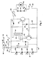
- a power source for the battery rejuvenator and trickle charger 10 shown comprised of a solar cell bank 12, including four (4) solar cells, 12A, 12B, 12C, and 12D connected in series. Each cell is capable of producing an output voltage of approximately 0.5 volts and therefore the voltage output of the bank of twelve (12) solar cells will be two (2) volts.
- Another power source 50 is shown available to be connected in parallel with the bank of solar cells when the battery is in a darkened environment.
- the current output of a solar cell is dependent upon the amount of incident light falling upon the cell. For a given incident light level, a solar cell puts out 250 milliamps. Above 250 milliamps the voltage output drops quickly. Below 250 milliamps the output voltage is fairly constant.
- the output of the solar cell bank 12 is applied by way of conductors 14 and 16 to a flyback network comprised of transformer 18 and switching transistor 20. With switching transistor 20 on and conducting current flows from the capacitor through the primary coil 22 of the transformer 18 to magnetize the core of the transformer. Current continues to flow into the capacitor 18 from the solar cell bank until the capacitor voltage reaches the maximum output voltage of the solar cell bank 12.
- the voltage across the capacitor 18 is sensed by a network including switching transistor 24, switching diode 26, and resistor 28. Switching transistor 24 turns on when the sensed voltage reaches the value V on .
- switching transistor 24 turns on switching transistor 20 and these transistors remain on while energy is transferred from the capacitor 18 to the primary of transformer 19.
- V off 2 x V sat + I b1 x R 30
- switching transistor 20 turns off, the voltage flies back in the secondary 32 of the transformer 19 to a value determined in part by the load, which includes the battery (not Shown) and diode 34, together with the turns ratio of the secondary coil of the transformer with respect to the primary coil.
- the fly back voltage may be utilized to charge either a 12 volt, a 24 volt, or a 36 volt battery.
- the fly back voltage causes diode 34 to forward bias and transfer current produced by induction in the secondary of the transformer 19 to a battery which will be connected to terminals 36 and 38 of the circuit 10.
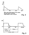
- the character of the current produced is in the form of high frequency pulses illustrated in Fig. 2. Wave forms representative of the current pulses in Fig. 2 were obtained across a 10 ohm resistor load. It will be observed that the current rise time is quite abrupt and then decays to 0 in approximately 84 ⁇ seconds. The current pulse peaked at 60 milliamps and had a repetition rate of 8.333 kilo Hz.
- the character of the voltage pulses produced is illustrated in Fig. 3 where the voltage is shown to rise very sharply, when switching transistor 20 is turned off, to a value of approximately 14 volts. The value of the voltage pulse falls off very slowly until the value of the current reaches zero, whereupon the voltage will drop exponentially and finally reach zero in approximately 52 ⁇ seconds.
- the peak pulse current produced by circuit 10 is greater than the leakage discharge current in a automobile battery.
- the effect of this is that a small average charge current can be effective in reducing or eliminating sulfate buildup on the plates of the lead acid storage battery over an extended period of time.
- the battery will therefore retain its ability to provide starting current over a long time and can be quickly recharged by a high current charger.
- the gentle spalling off of sulfate deposits on the plates of the battery by use of the present invention will allow the recovery and subsequent recharging of even old, otherwise unusable batteries.
- a visual indication that circuit 10 is operating is provided by a light emitting diode (LED) 40 connected in series with the positive terminal 36.
- LED light emitting diode
- circuit 10 The various components of circuit 10 are protected against an inadvertent connection of the terminals 36 and 38 to battery terminals of opposite polarity. When such a misconnection occurs, a high surge of current would occur, passing through diode 34 and damaging components of rejuvenator 10.
- Resistor 42 is provided to protect components of rejuvenator 10 from high current surges that might result from an error in connecting the terminals 36 and 38 to battery posts of opposite polarity.
- Resistor 42 is connected in series with the diode 34 and the positive terminal 36. It is a positive temperature coefficient resistor whose resistance increases significantly at a fairly low temperature. This change in resistance occurs rapidly and causes the current to fall to a level or levels that can be tolerated by the various components of the circuit 10. The components nominally can tolerate a current of 1 ampere.
- LED 40 Protecting the LED 40 from high current surges are a plurality of series-connected diodes 44, in turn connected in parallel with the LED 40. These diodes offer a very low impedance to current flow. In the event of a misconnection of the terminals, most of the current will flow through the diodes 44 to the positive temperature coefficient resistor 42. Further protection is provided for the solar cell bank 12 by the inclusion of diode 46 to prevent current flow to the solar cells when the terminals 36 and 38 are connected backward to battery terminals.
- the output of the rejuvenator 10 may be applied to battery terminals by way of a plug connected to output terminals 36 and 38, and inserted into a cigarette lighter located in a vehicle.
- the output of the rejuvenator 10 may be applied by way of an extension cord and clips to be connected directly to the battery terminals. It is this latter alternative connection that could give rise to an error in connecting the output of the rejuvenator to the battery to be treated.
- the other power source 50 to be connected when the battery is in a darkened environment, is shown comprised of an a.c. to d.c. converter 52.
- the converter 52 can be connected to a local source of a.c., usually 115 volts, by way of plug 54 to produce at its output 56 a d.c. voltage.
- the d.c. voltage is accessed by the rejuvenator and trickle charger 10 by way of plug 58 connected in parallel with the solar cell bank 12 through conductors 60 and 62.
- the converter 52 is available commercially and typically is of the type used to operate portable radios, hand held calculators and the like. In a prototype constructed of the present invention, the converter 52 had an output of 7.5 volts and 300 ma. In as much as the parameters of the rejuvenator and trickle charger 10 dictated a d.c. source of two (2) volts, resistor 64, having a value of eighteen (18) ohms, was added in series with conductor 62 to drop the voltage to two (2) volts at 300 milliamps. As the parameters of the rejuvenator and trickle charger 10 are changed as by the aforementioned use of Mosfet elements, the voltage output of the source 50 can be changed.
- the number of solar cells in bank 12 could be reduced to 1 through the use of Mosfet transistors which are operable at lower voltage levels; for example 1/2 volt.
Landscapes
- Engineering & Computer Science (AREA)
- Power Engineering (AREA)
- Charge And Discharge Circuits For Batteries Or The Like (AREA)
- Secondary Cells (AREA)
- Hybrid Cells (AREA)
- Protection Of Static Devices (AREA)
- Dc-Dc Converters (AREA)
- Battery Electrode And Active Subsutance (AREA)
Claims (16)
- Combinaison d'un régénérateur de batterie et d'un circuit de charge d'entretien de compensation pour des batteries plomb-acide, comprenant : une source de tension continue (12A-12D ; 50) ; un circuit de commutation (18, 19, 20, 24) pour la génération d'un signal en forme de train d'impulsions ayant des caractéristiques de courant et de tension du signal prédéterminées et des moyens (36 ; 38) pour la connexion de la tension continue et/ou du signal en forme de train d'impulsions généré ayant des caractéristiques de courant et de tension du signal prédéterminées à une paire de bornes d'une batterie pour assurer la charge d'entretien de compensation et/ou retirer le dépôt de sulfate ou empêcher la croissance de celui-ci, caractérisé en ce que la caractéristique prédéterminée de courant du signal comprend, pour chaque impulsion du signal en forme de train d'impulsions, une augmentation du courant sensiblement linéaire depuis un niveau de courant de base à une première vitesse d'évolution du courant, suivie d'une diminution du courant sensiblement linéaire à une seconde vitesse d'évolution du courant inférieure à la première vitesse d'évolution du courant, et en ce que la caractéristique prédéterminée de tension du signal comprend, pour chaque impulsion du signal en forme de train d'impulsions, une augmentation de la tension sensiblement linéaire depuis un niveau de tension de base à une première vitesse d'évolution de la tension, suivie d'une diminution de la tension sensiblement linéaire à une seconde vitesse d'évolution de la tension inférieure à la première vitesse d'évolution de la tension, suivie ensuite d'une chute de tension exponentielle jusqu'au niveau de tension de base.
- Circuit selon la revendication 1, le circuit de commutation étant caractérisé par un circuit de commutation de retour.
- Circuit selon la revendication 2, le circuit de commutation de retour comprenant : un condensateur (18) ; un transformateur (19) muni d'un bobinage primaire (22) et d'un bobinage secondaire (32), le bobinage secondaire étant relié par le biais de moyens de connexion à la batterie ; et des moyens de commutation (20, 24) pour détecter une tension emmagasinée dans le condensateur, les moyens de commutation se déclenchant en réponse à une tension détectée dépassant une première valeur, pour transférer la tension emmagasinée du condensateur vers le bobinage primaire du transformateur, et se déclenchant en réponse à une chute subséquente de la tension détectée à une valeur inférieure à une seconde valeur, pour retourner la tension du bobinage primaire vers le bobinage secondaire du transformateur pour son application à la batterie sous la forme d'une impulsion du signal en forme de train d'impulsions.
- Circuit selon la revendication 3, comprenant en outre une résistance à coefficient de température positive (42) branchée en série entre le bobinage secondaire et les moyens de connexion.
- Circuit selon la revendication 1, dans lequel la transition entre la diminution sensiblement linéaire de la tension et la diminution exponentielle de la tension des caractéristiques de tension prédéterminées a lieu lorsque la diminution sensiblement linéaire du courant atteint le niveau de courant de base.
- Circuit selon la revendication 1, caractérisé en outre en ce que le signal en forme de train d'impulsions a une fréquence d'environ huit kilohertz.
- Circuit selon la revendication 6, dans lequel la fréquence est particulièrement de 8,3 kilohertz.
- Circuit selon la revendication 1, dans lequel le courant de base est particulièrement de zéro ampères et la tension de base est particulièrement de zéro volts.
- Circuit selon la revendication 1, dans lequel le circuit de commutation est caractérisé par : un condensateur (18) ; un transformateur (19) muni d'un bobinage primaire (22) et d'un bobinage secondaire (32) ; et [des moyens de connexion du bobinage secondaire du transformateur à la batterie ; et] des moyens de commutation (20, 24) pour détecter une tension emmagasinée dans le condensateur, les moyens de commutation se déclenchant en réponse à une tension détectée dépassant une première valeur, pour transférer la tension emmagasinée du condensateur vers le bobinage primaire du transformateur, et se déclenchant en réponse à une chute subséquente de la tension détectée à une valeur inférieure à une seconde valeur, pour retourner la tension transférée du bobinage primaire vers le bobinage secondaire du transformateur, pour son application pulsée à la batterie par le biais des moyens de connexion.
- Circuit selon la revendication 9, comprenant en outre une résistance à coefficient de température positive branchée en série entre le bobinage secondaire et les moyens de connexion.
- Circuit selon la revendication 9, dans lequel les moyens de commutation comprennent : un premier transistor (20) pour connecter le condensateur au bobinage primaire du transformateur, et le déconnecter de celui-ci ; et un second transistor (24) connecté pour détecter la tension emmagasinée dans le condensateur, et en outre connecté pour commander la connexion et la déconnexion effectuée par le premier transistor, et ainsi connecter le condensateur au bobinage primaire lorsque la tension détectée dépasse la première valeur, et déconnecter le condensateur du bobinage primaire lorsque la tension détectée chute ensuite à une valeur inférieure à la seconde valeur.
- Circuit selon la revendication 1, dans lequel le circuit de commutation est caractérisé par : un condensateur (18) ; un transformateur (19) muni d'un bobinage primaire (22) et d'un bobinage secondaire (32) ; un premier commutateur (20) se déclenchant, lorsqu'il est activé, pour connecter le condensateur en parallèle avec le bobinage primaire du transformateur et, lorsqu'il est désactivé, pour déconnecter le condensateur du bobinage primaire du transformateur ; un second commutateur (24) connecté pour détecter une tension emmagasinée dans le condensateur et, en réponse à celle-ci, activer et désactiver le premier commutateur, générant ainsi un signal en forme de train d'impulsions au bobinage secondaire du transformateur.
- Circuit selon la revendication 12, dans lequel le signal en forme de train d'impulsions a une fréquence d'environ huit kilohertz.
- Circuit selon la revendication 13, dans lequel la fréquence est particulièrement de 8,3 kilohertz.
- Circuit selon la revendication 13, comprenant en outre une résistance à coefficient de température positive (42) branché en série entre le bobinage secondaire et les moyens de connexion.
- Circuit selon la revendication 13, dans lequel le second commutateur active le premier commutateur lorsque la tension détectée dans le condensateur augmente pour dépasser une première valeur, et désactive le premier commutateur lorsque la tension détectée dans le condensateur chute en dessous d'une seconde valeur.
Applications Claiming Priority (2)
| Application Number | Priority Date | Filing Date | Title |
|---|---|---|---|
| US08/092,515 US5491399A (en) | 1993-05-28 | 1993-07-16 | Lead acid battery rejuvenator |
| PCT/US1994/011289 WO1996011522A1 (fr) | 1993-07-16 | 1994-10-06 | Chargeur de maintien et regenerateur pour accumulateur au plomb |
Publications (3)
| Publication Number | Publication Date |
|---|---|
| EP0801834A1 EP0801834A1 (fr) | 1997-10-22 |
| EP0801834A4 EP0801834A4 (fr) | 1999-06-02 |
| EP0801834B1 true EP0801834B1 (fr) | 2005-12-28 |
Family
ID=26785770
Family Applications (1)
| Application Number | Title | Priority Date | Filing Date |
|---|---|---|---|
| EP95903099A Expired - Lifetime EP0801834B1 (fr) | 1993-07-16 | 1994-10-06 | Chargeur de maintien et regenerateur pour accumulateur au plomb |
Country Status (10)
| Country | Link |
|---|---|
| US (1) | US5491399A (fr) |
| EP (1) | EP0801834B1 (fr) |
| JP (1) | JP3079212B2 (fr) |
| AT (1) | ATE314748T1 (fr) |
| AU (1) | AU703174B2 (fr) |
| BR (1) | BR9408628A (fr) |
| CA (1) | CA2201902C (fr) |
| DE (1) | DE69434595T2 (fr) |
| NZ (1) | NZ277153A (fr) |
| WO (1) | WO1996011522A1 (fr) |
Cited By (7)
| Publication number | Priority date | Publication date | Assignee | Title |
|---|---|---|---|---|
| US7923151B2 (en) | 2003-09-18 | 2011-04-12 | Commonwealth Scientific And Industrial Research Organisation | High performance energy storage devices |
| US9203116B2 (en) | 2006-12-12 | 2015-12-01 | Commonwealth Scientific And Industrial Research Organisation | Energy storage device |
| US9450232B2 (en) | 2009-04-23 | 2016-09-20 | Commonwealth Scientific And Industrial Research Organisation | Process for producing negative plate for lead storage battery, and lead storage battery |
| US9508493B2 (en) | 2009-08-27 | 2016-11-29 | The Furukawa Battery Co., Ltd. | Hybrid negative plate for lead-acid storage battery and lead-acid storage battery |
| US9524831B2 (en) | 2009-08-27 | 2016-12-20 | The Furukawa Battery Co., Ltd. | Method for producing hybrid negative plate for lead-acid storage battery and lead-acid storage battery |
| US9666860B2 (en) | 2007-03-20 | 2017-05-30 | Commonwealth Scientific And Industrial Research Organisation | Optimised energy storage device having capacitor material on lead based negative electrode |
| US9812703B2 (en) | 2010-12-21 | 2017-11-07 | Commonwealth Scientific And Industrial Research Organisation | Electrode and electrical storage device for lead-acid system |
Families Citing this family (27)
| Publication number | Priority date | Publication date | Assignee | Title |
|---|---|---|---|---|
| US5592068A (en) * | 1993-05-28 | 1997-01-07 | William E. Gregory | Lead acid battery rejuvenator |
| US5633575A (en) * | 1994-03-31 | 1997-05-27 | Gali; Carl E. | Battery reclaimer and charger |
| US5648714A (en) * | 1994-11-30 | 1997-07-15 | 3266991 Manitoba Ltd. | Method and device for charging and conditioning batteries |
| US5677612A (en) * | 1996-08-02 | 1997-10-14 | The United States Of America As Represented By The Secretary Of The Army | Lead-acid battery desulfator/rejuvenator |
| US5744935A (en) * | 1996-08-06 | 1998-04-28 | Khoury; Omar Fuad | Process and apparatus for nickel-cadmium battery revival |
| WO1998021804A1 (fr) * | 1996-11-08 | 1998-05-22 | Lajos Koltai | Procede et circuit electrique pour accroitre la duree de vie de batteries d'accumulateurs |
| CA2201977C (fr) * | 1997-04-07 | 2002-02-26 | Thomas J. King | Dispositif de reconditionnement de batterie |
| US6566844B1 (en) * | 1999-10-06 | 2003-05-20 | Battery Performance Technologies, Inc. | Method and apparatus for extending the functionality of a battery |
| US6184650B1 (en) | 1999-11-22 | 2001-02-06 | Synergistic Technologies, Inc. | Apparatus for charging and desulfating lead-acid batteries |
| EP1250745B1 (fr) * | 2000-01-12 | 2004-10-13 | Wiedmann, Alwin | Dispositif pour regenerer des accumulateurs |
| US6469473B1 (en) | 2001-03-16 | 2002-10-22 | Battery Performance Technologies, Inc. | Method and apparatus for using pulse current to extend the functionality of a battery |
| US20030183268A1 (en) * | 2002-03-29 | 2003-10-02 | Shanefield Daniel Jay | Device for conversion of environmental thermal energy into direct current electricity |
| ATE416489T1 (de) * | 2003-02-03 | 2008-12-15 | Kelly Shawn P | Verfahren und seine vorrichtung zur effizienzverbesserung und zum verhindern der zersetzung dieser energiespeichervorrichtung |
| US7376836B2 (en) * | 2003-09-19 | 2008-05-20 | Nortel Networks Limited | Systems and methods for preventing an attack on healthcare data processing resources in a hospital information system |
| US7528579B2 (en) * | 2003-10-23 | 2009-05-05 | Schumacher Electric Corporation | System and method for charging batteries |
| WO2008022490A1 (fr) * | 2006-08-18 | 2008-02-28 | Fengyue Bu | Régénérateur pour régénérer des batteries |
| US8269466B2 (en) * | 2007-09-27 | 2012-09-18 | Pulsetech Products Corporation | Method for charging a battery including an oscillating triangular waveform to remove sulphate from battery plates |
| KR100931510B1 (ko) * | 2009-01-12 | 2009-12-11 | (주)마루엠씨에스 | 축전지의 재생 장치 |
| US20100301800A1 (en) * | 2009-05-26 | 2010-12-02 | Mathew Inskeep | Multi-purpose battery jump starter and reconditioner |
| ITPA20090016A1 (it) * | 2009-07-13 | 2011-01-14 | Ludovico Ingoglia | Sistema di controllo di ricarica per batterie di veicoli elettrici. |
| US9401508B2 (en) | 2009-08-27 | 2016-07-26 | Commonwealth Scientific And Industrial Research Organisation | Electrical storage device and electrode thereof |
| US8760107B2 (en) * | 2010-01-04 | 2014-06-24 | Alexander Stephan Kiss | Anchor charger |
| CN103490114A (zh) * | 2013-05-22 | 2014-01-01 | 厦门宇虹达光电科技有限公司 | 蓄电池充电再生器 |
| EP3031301B1 (fr) | 2013-11-04 | 2017-04-05 | Philips Lighting Holding B.V. | Dispositif de protection contre les surtensions |
| CN104332671B (zh) * | 2014-09-05 | 2015-08-05 | 南阳师范学院 | 一种铅蓄电池再生装置及再生方法 |
| WO2019051339A1 (fr) * | 2017-09-08 | 2019-03-14 | Donofrio Brett | Module pour consommation de batterie améliorée |
| US12479557B1 (en) | 2022-12-29 | 2025-11-25 | Brunswick Corporation | Marine propulsion system with pre-charge and discharge circuit |
Family Cites Families (24)
| Publication number | Priority date | Publication date | Assignee | Title |
|---|---|---|---|---|
| US3586955A (en) * | 1970-03-31 | 1971-06-22 | Crawford Fitting Co | Battery charger using a controlled scr to provide tapering charging characteristics |
| US4214198A (en) * | 1977-09-01 | 1980-07-22 | Dynamote Corporation | Electrical power unit |
| US4183080A (en) * | 1978-06-21 | 1980-01-08 | Theodore Liebman | DC to DC converter |
| US4246634A (en) * | 1979-03-07 | 1981-01-20 | Ann Arbor Terminals, Inc. | Start-up circuit for switch mode power supply |
| US4363005A (en) * | 1979-07-03 | 1982-12-07 | Dentan Kabushiki Kaisha | Power conserving blocking oscillator power supply circuit |
| JPS5691632A (en) * | 1979-12-26 | 1981-07-24 | Fuji Electric Co Ltd | Solar battery utilizing power source |
| US4366430A (en) * | 1980-09-29 | 1982-12-28 | Associated Equipment Corporation | Battery booster cable assembly |
| US4422138A (en) * | 1981-12-11 | 1983-12-20 | General Electric Company | Power supply for low-voltage load |
| JPS6289435A (ja) * | 1985-06-18 | 1987-04-23 | 三洋電機株式会社 | 充電装置 |
| JPH0521949Y2 (fr) * | 1985-12-02 | 1993-06-04 | ||
| US4882663A (en) * | 1985-12-23 | 1989-11-21 | Nilssen Ole K | MOSFET flyback converter |
| US4750102A (en) * | 1986-03-20 | 1988-06-07 | Sanyo Electric Co., Ltd. | Power converting apparatus |
| JPS62225137A (ja) * | 1986-03-25 | 1987-10-03 | 北村 重信 | 自動車バツテリ緊急時のための対応装置 |
| US4728877A (en) * | 1986-06-10 | 1988-03-01 | Adaptive Instruments Corp. | Method and apparatus for improving electrochemical processes |
| US4740739A (en) * | 1987-02-10 | 1988-04-26 | Premier Engineered Products Corporation | Battery charging apparatus and method |
| US5049804A (en) * | 1987-06-01 | 1991-09-17 | Power-Tech Systems Corporation | Universal battery charging system and a method |
| JPH01238028A (ja) * | 1988-03-18 | 1989-09-22 | Hitachi Ltd | 基板へのwsiウエハまたはicチップ取付構造 |
| US4871959A (en) * | 1988-07-15 | 1989-10-03 | Gali Carl E | Solar trickle charger for lead acid batteries |
| US4965507A (en) * | 1989-07-07 | 1990-10-23 | Eveready Battery Company, Inc. | Battery charger for detecting the current rate of charge for rechargeable batteries |
| US5084664A (en) * | 1990-10-16 | 1992-01-28 | Gali Carl E | Solar powered lead acid battery rejuvenator and trickle charger |
| US5063341A (en) * | 1990-10-16 | 1991-11-05 | Gali Carl E | Lead acid battery rejuvenator and charger |
| JPH0538060A (ja) * | 1991-07-31 | 1993-02-12 | Matsushita Electric Ind Co Ltd | 充電回路 |
| JPH0690531A (ja) * | 1992-07-21 | 1994-03-29 | Sony Corp | 充電装置 |
| DE4308538A1 (de) * | 1993-03-17 | 1994-09-22 | Rotermund Ulli | Verfahren und Vorrichtung zum Regenerieren von Spannungsquellen in Form galvanischer Elemente, insbesondere von Primärelementen |
-
1993
- 1993-07-16 US US08/092,515 patent/US5491399A/en not_active Expired - Lifetime
-
1994
- 1994-10-06 WO PCT/US1994/011289 patent/WO1996011522A1/fr not_active Ceased
- 1994-10-06 AU AU12083/95A patent/AU703174B2/en not_active Ceased
- 1994-10-06 EP EP95903099A patent/EP0801834B1/fr not_active Expired - Lifetime
- 1994-10-06 NZ NZ277153A patent/NZ277153A/xx unknown
- 1994-10-06 DE DE69434595T patent/DE69434595T2/de not_active Expired - Fee Related
- 1994-10-06 CA CA002201902A patent/CA2201902C/fr not_active Expired - Fee Related
- 1994-10-06 BR BR9408628A patent/BR9408628A/pt not_active Application Discontinuation
- 1994-10-06 AT AT95903099T patent/ATE314748T1/de not_active IP Right Cessation
- 1994-10-06 JP JP07505412A patent/JP3079212B2/ja not_active Expired - Fee Related
Cited By (8)
| Publication number | Priority date | Publication date | Assignee | Title |
|---|---|---|---|---|
| US7923151B2 (en) | 2003-09-18 | 2011-04-12 | Commonwealth Scientific And Industrial Research Organisation | High performance energy storage devices |
| US8232006B2 (en) | 2003-09-18 | 2012-07-31 | Commonwealth Scientific And Industrial Research Organisation | High performance energy storage devices |
| US9203116B2 (en) | 2006-12-12 | 2015-12-01 | Commonwealth Scientific And Industrial Research Organisation | Energy storage device |
| US9666860B2 (en) | 2007-03-20 | 2017-05-30 | Commonwealth Scientific And Industrial Research Organisation | Optimised energy storage device having capacitor material on lead based negative electrode |
| US9450232B2 (en) | 2009-04-23 | 2016-09-20 | Commonwealth Scientific And Industrial Research Organisation | Process for producing negative plate for lead storage battery, and lead storage battery |
| US9508493B2 (en) | 2009-08-27 | 2016-11-29 | The Furukawa Battery Co., Ltd. | Hybrid negative plate for lead-acid storage battery and lead-acid storage battery |
| US9524831B2 (en) | 2009-08-27 | 2016-12-20 | The Furukawa Battery Co., Ltd. | Method for producing hybrid negative plate for lead-acid storage battery and lead-acid storage battery |
| US9812703B2 (en) | 2010-12-21 | 2017-11-07 | Commonwealth Scientific And Industrial Research Organisation | Electrode and electrical storage device for lead-acid system |
Also Published As
| Publication number | Publication date |
|---|---|
| EP0801834A4 (fr) | 1999-06-02 |
| ATE314748T1 (de) | 2006-01-15 |
| WO1996011522A1 (fr) | 1996-04-18 |
| US5491399A (en) | 1996-02-13 |
| AU1208395A (en) | 1996-05-02 |
| AU703174B2 (en) | 1999-03-18 |
| CA2201902A1 (fr) | 1996-04-18 |
| NZ277153A (en) | 1998-10-28 |
| EP0801834A1 (fr) | 1997-10-22 |
| DE69434595D1 (de) | 2006-02-02 |
| BR9408628A (pt) | 1997-09-16 |
| DE69434595T2 (de) | 2006-08-10 |
| CA2201902C (fr) | 2004-04-13 |
| JP3079212B2 (ja) | 2000-08-21 |
| JPH09502076A (ja) | 1997-02-25 |
Similar Documents
| Publication | Publication Date | Title |
|---|---|---|
| CA2201902C (fr) | Regenerateur pour batterie d'accumulateurs au plomb | |
| US4710694A (en) | Microprocessor controlled battery charger | |
| US4742290A (en) | Recharging battery charger | |
| US5084664A (en) | Solar powered lead acid battery rejuvenator and trickle charger | |
| US4376263A (en) | Battery charging circuit | |
| US4583035A (en) | Apparatus for monitoring and charging electric storage battery | |
| US5523667A (en) | Alkaline battery charger and method of operating same | |
| CA2372933C (fr) | Procede et dispositif de chargement rapide de batterie | |
| US6198251B1 (en) | Method for sequentially charging batteries in situ | |
| US5592068A (en) | Lead acid battery rejuvenator | |
| WO1998031088A2 (fr) | Procede et appareil ameliores permettant de charger et de regenerer rapidement une batterie | |
| US5541495A (en) | Battery polarity connection adaption solid state switch | |
| WO2001018900A1 (fr) | Systeme de chargement a ions de lithium et procede utilisant le controle de la liberation d'ions | |
| US4969229A (en) | Battery-operated surface treatment apparatus having a booster function | |
| CN1065988C (zh) | 铅酸电池再生器 | |
| CA2484161C (fr) | Bloc d'alimentation rechargeable | |
| US5831416A (en) | Apparatus and method for charging batteries | |
| US4467264A (en) | Battery charger with visual charge indicating means | |
| AU2002255146A1 (en) | Power supply | |
| MXPA95003678A (es) | Rejuvenecedor de bateria de acido de plomo y dispositivo de carga lenta. | |
| EP0539775A3 (en) | Device for charging a battery | |
| JPS62188176A (ja) | 乾電池の使用寿命を大幅に延長するための方法及びその装置 | |
| JPH0965580A (ja) | 二次電池充電装置 | |
| JPH07212983A (ja) | 二次電池電圧制御装置 | |
| KR19980052709A (ko) | 밧데리 과충전 보호기 |
Legal Events
| Date | Code | Title | Description |
|---|---|---|---|
| PUAI | Public reference made under article 153(3) epc to a published international application that has entered the european phase |
Free format text: ORIGINAL CODE: 0009012 |
|
| 17P | Request for examination filed |
Effective date: 19970418 |
|
| AK | Designated contracting states |
Kind code of ref document: A1 Designated state(s): AT BE CH DE DK ES FR GB IE IT LI NL PT SE |
|
| A4 | Supplementary search report drawn up and despatched |
Effective date: 19990416 |
|
| AK | Designated contracting states |
Kind code of ref document: A4 Designated state(s): AT BE CH DE DK ES FR GB IE IT LI NL PT SE |
|
| RAP1 | Party data changed (applicant data changed or rights of an application transferred) |
Owner name: PULSETECH PRODUCTS CORPORATION |
|
| RIN1 | Information on inventor provided before grant (corrected) |
Inventor name: CHESTER, C. ALLEN, JR. Inventor name: GREGORY, WILLIAM E. |
|
| 17Q | First examination report despatched |
Effective date: 20050301 |
|
| GRAP | Despatch of communication of intention to grant a patent |
Free format text: ORIGINAL CODE: EPIDOSNIGR1 |
|
| GRAS | Grant fee paid |
Free format text: ORIGINAL CODE: EPIDOSNIGR3 |
|
| GRAA | (expected) grant |
Free format text: ORIGINAL CODE: 0009210 |
|
| AK | Designated contracting states |
Kind code of ref document: B1 Designated state(s): AT BE CH DE DK ES FR GB IE IT LI NL PT SE |
|
| PG25 | Lapsed in a contracting state [announced via postgrant information from national office to epo] |
Ref country code: NL Free format text: LAPSE BECAUSE OF FAILURE TO SUBMIT A TRANSLATION OF THE DESCRIPTION OR TO PAY THE FEE WITHIN THE PRESCRIBED TIME-LIMIT Effective date: 20051228 Ref country code: LI Free format text: LAPSE BECAUSE OF FAILURE TO SUBMIT A TRANSLATION OF THE DESCRIPTION OR TO PAY THE FEE WITHIN THE PRESCRIBED TIME-LIMIT Effective date: 20051228 Ref country code: IT Free format text: LAPSE BECAUSE OF FAILURE TO SUBMIT A TRANSLATION OF THE DESCRIPTION OR TO PAY THE FEE WITHIN THE PRESCRIBED TIME-LIMIT;WARNING: LAPSES OF ITALIAN PATENTS WITH EFFECTIVE DATE BEFORE 2007 MAY HAVE OCCURRED AT ANY TIME BEFORE 2007. THE CORRECT EFFECTIVE DATE MAY BE DIFFERENT FROM THE ONE RECORDED. Effective date: 20051228 Ref country code: CH Free format text: LAPSE BECAUSE OF FAILURE TO SUBMIT A TRANSLATION OF THE DESCRIPTION OR TO PAY THE FEE WITHIN THE PRESCRIBED TIME-LIMIT Effective date: 20051228 Ref country code: BE Free format text: LAPSE BECAUSE OF FAILURE TO SUBMIT A TRANSLATION OF THE DESCRIPTION OR TO PAY THE FEE WITHIN THE PRESCRIBED TIME-LIMIT Effective date: 20051228 |
|
| REG | Reference to a national code |
Ref country code: GB Ref legal event code: FG4D |
|
| REG | Reference to a national code |
Ref country code: CH Ref legal event code: EP |
|
| REG | Reference to a national code |
Ref country code: IE Ref legal event code: FG4D |
|
| REF | Corresponds to: |
Ref document number: 69434595 Country of ref document: DE Date of ref document: 20060202 Kind code of ref document: P |
|
| PG25 | Lapsed in a contracting state [announced via postgrant information from national office to epo] |
Ref country code: DK Free format text: LAPSE BECAUSE OF FAILURE TO SUBMIT A TRANSLATION OF THE DESCRIPTION OR TO PAY THE FEE WITHIN THE PRESCRIBED TIME-LIMIT Effective date: 20060328 |
|
| PG25 | Lapsed in a contracting state [announced via postgrant information from national office to epo] |
Ref country code: ES Free format text: LAPSE BECAUSE OF FAILURE TO SUBMIT A TRANSLATION OF THE DESCRIPTION OR TO PAY THE FEE WITHIN THE PRESCRIBED TIME-LIMIT Effective date: 20060408 |
|
| REG | Reference to a national code |
Ref country code: SE Ref legal event code: TRGR |
|
| RIN2 | Information on inventor provided after grant (corrected) |
Inventor name: CHESTER, C. ALLEN, JR. Inventor name: GREGORY, WILLIAM E. |
|
| PG25 | Lapsed in a contracting state [announced via postgrant information from national office to epo] |
Ref country code: PT Free format text: LAPSE BECAUSE OF FAILURE TO SUBMIT A TRANSLATION OF THE DESCRIPTION OR TO PAY THE FEE WITHIN THE PRESCRIBED TIME-LIMIT Effective date: 20060529 |
|
| NLV1 | Nl: lapsed or annulled due to failure to fulfill the requirements of art. 29p and 29m of the patents act | ||
| REG | Reference to a national code |
Ref country code: CH Ref legal event code: PL |
|
| ET | Fr: translation filed | ||
| PG25 | Lapsed in a contracting state [announced via postgrant information from national office to epo] |
Ref country code: IE Free format text: LAPSE BECAUSE OF NON-PAYMENT OF DUE FEES Effective date: 20061006 |
|
| PLBE | No opposition filed within time limit |
Free format text: ORIGINAL CODE: 0009261 |
|
| STAA | Information on the status of an ep patent application or granted ep patent |
Free format text: STATUS: NO OPPOSITION FILED WITHIN TIME LIMIT |
|
| 26N | No opposition filed |
Effective date: 20060929 |
|
| REG | Reference to a national code |
Ref country code: IE Ref legal event code: MM4A |
|
| PGFP | Annual fee paid to national office [announced via postgrant information from national office to epo] |
Ref country code: DE Payment date: 20071004 Year of fee payment: 14 |
|
| PGFP | Annual fee paid to national office [announced via postgrant information from national office to epo] |
Ref country code: AT Payment date: 20071011 Year of fee payment: 14 Ref country code: IT Payment date: 20071026 Year of fee payment: 14 |
|
| PGFP | Annual fee paid to national office [announced via postgrant information from national office to epo] |
Ref country code: FR Payment date: 20071009 Year of fee payment: 14 |
|
| REG | Reference to a national code |
Ref country code: FR Ref legal event code: ST Effective date: 20090630 |
|
| PG25 | Lapsed in a contracting state [announced via postgrant information from national office to epo] |
Ref country code: IT Free format text: LAPSE BECAUSE OF NON-PAYMENT OF DUE FEES Effective date: 20081006 Ref country code: DE Free format text: LAPSE BECAUSE OF NON-PAYMENT OF DUE FEES Effective date: 20090501 Ref country code: AT Free format text: LAPSE BECAUSE OF NON-PAYMENT OF DUE FEES Effective date: 20081006 |
|
| PG25 | Lapsed in a contracting state [announced via postgrant information from national office to epo] |
Ref country code: FR Free format text: LAPSE BECAUSE OF NON-PAYMENT OF DUE FEES Effective date: 20081031 |
|
| PGFP | Annual fee paid to national office [announced via postgrant information from national office to epo] |
Ref country code: SE Payment date: 20101012 Year of fee payment: 17 Ref country code: GB Payment date: 20101006 Year of fee payment: 17 |
|
| GBPC | Gb: european patent ceased through non-payment of renewal fee |
Effective date: 20111006 |
|
| REG | Reference to a national code |
Ref country code: SE Ref legal event code: EUG |
|
| PG25 | Lapsed in a contracting state [announced via postgrant information from national office to epo] |
Ref country code: GB Free format text: LAPSE BECAUSE OF NON-PAYMENT OF DUE FEES Effective date: 20111006 |
|
| PG25 | Lapsed in a contracting state [announced via postgrant information from national office to epo] |
Ref country code: SE Free format text: LAPSE BECAUSE OF NON-PAYMENT OF DUE FEES Effective date: 20111007 |