EP0801989A1 - Procédé de flottation et dispositif pour sa mise en oeuvre - Google Patents
Procédé de flottation et dispositif pour sa mise en oeuvre Download PDFInfo
- Publication number
- EP0801989A1 EP0801989A1 EP97102625A EP97102625A EP0801989A1 EP 0801989 A1 EP0801989 A1 EP 0801989A1 EP 97102625 A EP97102625 A EP 97102625A EP 97102625 A EP97102625 A EP 97102625A EP 0801989 A1 EP0801989 A1 EP 0801989A1
- Authority
- EP
- European Patent Office
- Prior art keywords
- flotation
- suspension
- inlet opening
- mixing element
- mixing
- Prior art date
- Legal status (The legal status is an assumption and is not a legal conclusion. Google has not performed a legal analysis and makes no representation as to the accuracy of the status listed.)
- Granted
Links
- 238000005188 flotation Methods 0.000 title claims abstract description 81
- 238000000034 method Methods 0.000 title claims abstract description 35
- 239000000725 suspension Substances 0.000 claims abstract description 45
- 230000008569 process Effects 0.000 claims abstract description 26
- 239000007787 solid Substances 0.000 claims description 9
- 230000000694 effects Effects 0.000 claims description 8
- 239000000835 fiber Substances 0.000 claims description 6
- 239000006260 foam Substances 0.000 claims description 4
- 229920001131 Pulp (paper) Polymers 0.000 claims description 3
- 239000000463 material Substances 0.000 claims 1
- 239000000356 contaminant Substances 0.000 abstract description 2
- 239000002657 fibrous material Substances 0.000 abstract 1
- 239000000203 mixture Substances 0.000 abstract 1
- 239000002245 particle Substances 0.000 description 3
- 238000000926 separation method Methods 0.000 description 2
- 239000000126 substance Substances 0.000 description 2
- 239000000853 adhesive Substances 0.000 description 1
- 230000001070 adhesive effect Effects 0.000 description 1
- 230000002411 adverse Effects 0.000 description 1
- 230000008859 change Effects 0.000 description 1
- 238000006243 chemical reaction Methods 0.000 description 1
- 238000005352 clarification Methods 0.000 description 1
- 230000003749 cleanliness Effects 0.000 description 1
- 239000000470 constituent Substances 0.000 description 1
- 230000002349 favourable effect Effects 0.000 description 1
- 238000003958 fumigation Methods 0.000 description 1
- 230000002209 hydrophobic effect Effects 0.000 description 1
- 239000012535 impurity Substances 0.000 description 1
- 239000000976 ink Substances 0.000 description 1
- 230000007246 mechanism Effects 0.000 description 1
- 230000004048 modification Effects 0.000 description 1
- 238000012986 modification Methods 0.000 description 1
- 239000010893 paper waste Substances 0.000 description 1
- 230000021715 photosynthesis, light harvesting Effects 0.000 description 1
- 238000001228 spectrum Methods 0.000 description 1
- 238000011144 upstream manufacturing Methods 0.000 description 1
- 239000002699 waste material Substances 0.000 description 1
- 239000002351 wastewater Substances 0.000 description 1
- XLYOFNOQVPJJNP-UHFFFAOYSA-N water Substances O XLYOFNOQVPJJNP-UHFFFAOYSA-N 0.000 description 1
Images


Classifications
-
- D—TEXTILES; PAPER
- D21—PAPER-MAKING; PRODUCTION OF CELLULOSE
- D21F—PAPER-MAKING MACHINES; METHODS OF PRODUCING PAPER THEREON
- D21F1/00—Wet end of machines for making continuous webs of paper
- D21F1/66—Pulp catching, de-watering, or recovering; Re-use of pulp-water
- D21F1/70—Pulp catching, de-watering, or recovering; Re-use of pulp-water by flotation
-
- B—PERFORMING OPERATIONS; TRANSPORTING
- B03—SEPARATION OF SOLID MATERIALS USING LIQUIDS OR USING PNEUMATIC TABLES OR JIGS; MAGNETIC OR ELECTROSTATIC SEPARATION OF SOLID MATERIALS FROM SOLID MATERIALS OR FLUIDS; SEPARATION BY HIGH-VOLTAGE ELECTRIC FIELDS
- B03D—FLOTATION; DIFFERENTIAL SEDIMENTATION
- B03D1/00—Flotation
- B03D1/02—Froth-flotation processes
- B03D1/028—Control and monitoring of flotation processes; computer models therefor
-
- B—PERFORMING OPERATIONS; TRANSPORTING
- B03—SEPARATION OF SOLID MATERIALS USING LIQUIDS OR USING PNEUMATIC TABLES OR JIGS; MAGNETIC OR ELECTROSTATIC SEPARATION OF SOLID MATERIALS FROM SOLID MATERIALS OR FLUIDS; SEPARATION BY HIGH-VOLTAGE ELECTRIC FIELDS
- B03D—FLOTATION; DIFFERENTIAL SEDIMENTATION
- B03D1/00—Flotation
- B03D1/14—Flotation machines
- B03D1/1493—Flotation machines with means for establishing a specified flow pattern
-
- B—PERFORMING OPERATIONS; TRANSPORTING
- B03—SEPARATION OF SOLID MATERIALS USING LIQUIDS OR USING PNEUMATIC TABLES OR JIGS; MAGNETIC OR ELECTROSTATIC SEPARATION OF SOLID MATERIALS FROM SOLID MATERIALS OR FLUIDS; SEPARATION BY HIGH-VOLTAGE ELECTRIC FIELDS
- B03D—FLOTATION; DIFFERENTIAL SEDIMENTATION
- B03D1/00—Flotation
- B03D1/14—Flotation machines
- B03D1/24—Pneumatic
- B03D1/247—Mixing gas and slurry in a device separate from the flotation tank, i.e. reactor-separator type
Definitions
- the invention relates to a flotation process for separating solids from a paper-containing suspension according to the preamble of claim 1 and a mixing device according to the preamble of claim 17.
- Methods of this type are e.g. known from DE-OS 34 01 161. They are used in the paper industry for the removal of printing inks, adhesives or other disruptive contaminants, most of which come from waste paper. Due to its hydrophobicity, the fiber is removed as a good substance in the suspension, while the contaminating solids are discarded with the foam. Because of this division of the solid streams into fibers and impurities, one speaks of selective flotation. Other uses of such processes are also known in which as much of the solids as possible is removed by flotation, e.g. in the treatment of waste water generated by pressing in the paper industry. In such cases, one speaks of clarification flotation or, because of the gassing mechanism, relaxation flotation.
- the object of the invention is therefore to create a flotation process with a better separation effect and / or a lower specific energy requirement.
- Better separation means that the amount of the undesired constituents of the paper pulp suspension removed is further increased, that is to say a better cleanliness of the pulp or less fiber loss or both.
- the pulse exchange in the area of the mixing element is such that the specifically required energy dissipation takes place in order to promote the attachment of hydrophobic solid particles to the bubbles. Neither the air bubbles are adversely changed, nor are particles already attached to air bubbles torn off again. Rather, if desired, the bubble size can be better influenced by the process. It has been shown that a bubble size spectrum in accordance with the requirements, especially in fiber suspensions, is difficult to produce or unstable by conventional injectors alone. In the new process, the entire energy conversion takes place under particularly favorable conditions, in particular in comparison to the known injectors, since the speeds can be lower because of the larger volumes involved.
- the suspension in the flotation container is given a rotational movement because the mixing element generates a suction that is effective within the flotation container.
- This recirculation movement therefore increases the likelihood that solid particles to be separated can come into contact with the air bubbles entered. This also improves the separating effect of the flotation process.
- the suction effect described is also suitable for subtracting the vortices which, in the prior art, can arise directly at the mouth of the inlet pipe into the flotation container. These vortices disrupt flotation and waste energy unnecessarily. If they are suctioned off according to the invention, their energy can be used for fumigation and mixing.
- the rotational movement is controlled so that it cannot damage the flotation. That means: The movement of the gas bubbles to the surface still takes place in the necessary way, since the circulating flow is locally limited to a small part of the suspension in the flotation tank.
- the suspension preferably leaves the mixing element in an approximately horizontal direction, which also applies to a vertically arranged inlet line.
- the flotation apparatus contains a flotation container 1 which is not completely drawn. When the method is carried out, this is largely filled with suspension, on the surface of which, as is known per se, a foam 8 is formed which contains as large a part as possible of the components to be flotated. It can flow off via a foam weir as reject R.
- the suspension S 1 containing paper pulp enters the flotation container 1 through an inlet element 6 having an inlet opening 2. As shown here, it can be mixed with gas G, for example air, before entering the flotation container.
- the inflowing suspension is passed through a mixing element 3, the inflow opening 4 of which is located at a distance a from the inlet opening 2.
- part of the suspension S 2 located in the flotation container 1 is sucked into the space between the inlet opening 2 and the inflow opening 4.
- This space has the Function of a collecting room 7 (Fig. 2).
- the suspension cleaned by flotation exits the flotation container 1 as accept substance A through the outlet opening 5.
- this is a fiber suspension freed from foreign matter or in special cases clarified water, in which the largest possible proportion of all the solids contained has been removed by the flotation.
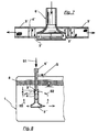
- FIG. 2 mixing element 3 and the associated inlet element 6 are drawn somewhat more detailed, but still schematically.
- the collecting space 7 between the inlet opening 2 and the inflow opening 4 is indicated by dashed lines.
- the mixing element 3 has the extension c.
- a special feature is the offset b between the center lines of both openings. This offset can be changeable to regulate the mixing effect, especially when it is difficult to change the distance a for constructional reasons. This would be the case with radial flow guidance, such as in FIGS. 6 and 7.
- the offset b influences the recirculation of the suspension within the flotation container.
- the arrangement shown in FIG. 2 favors the suction of the suspension above the mixing element 3 due to the offset.
- the inlet opening 2 is not flush with the wall of the flotation container 1, which can have advantages in flotation.
- the inlet opening 2 can also be located in the container wall.
- the bubble-forming gas G is pumped directly through the wall into the flotation tank 1. This variant is also possible with other arrangements.
- the size of the distance a determines the mixing and thus also the flotation effect. Therefore, changing them can be used as a way to control the flotation process.
- FIG. 4 A simple example of this is shown in FIG. 4, in which the mixing element 3 is slidably connected to the inlet element 6. This shift can also be done with a motor and the motor as an actuator function of a control loop.
- the adjustability can be implemented in various ways and is familiar to the person skilled in the art.
- the mixing element 3 forms a unit with the inlet element 6.
- the suspension that is already in the flotation tank is sucked in through elongated holes that are arranged upstream of the mixing element 3. In this way, even with this simple device, there is a distance a between the inlet opening 2 and the inflow opening 4, these openings being indicated here as ovals.
- FIG. 6 shows the section through a flotation container 1 'which, in contrast to that in FIG. 1, has an oval cross section.
- the suspension S 1 is fed into this container and aerated through an inlet element 6 ', which has a cylindrical inlet opening.
- the inlet element 6 ' can advantageously, as shown here, be attached eccentrically in the flotation tank 1'.
- the method according to the invention can also be used in such a flotation device, the mixing element 3 'being positioned essentially in a ring around the inlet opening 2' because of the radial inflow of the suspension.
- the conditions in the described area of the inlet element 6 ' are shown in somewhat more detail in FIG. 7.
- the mixing element has a height offset relative to the inlet opening 2 '. This is not necessary, but can be used to regulate the mixing in the flotation tank, as already stated.
- the mechanical implementation of this adjustment option is not shown here, it is familiar to the person skilled in the art.
- the mixing element 3 ′′ can also be of the type as it is 8 is shown.
- the suspension S 1 is entered vertically into the flotation container 1 through the inlet element 6 ', both the inlet opening 2''and the inflow opening 4''being horizontal.
- the mixing element 3 ′′ which has a correspondingly designed channel.
- the mixing element 3 ′′ can again be arranged displaceably relative to the inlet part 6 ′ in order to thereby control the flotation process.
Landscapes
- Engineering & Computer Science (AREA)
- Life Sciences & Earth Sciences (AREA)
- Biotechnology (AREA)
- General Engineering & Computer Science (AREA)
- Paper (AREA)
- Processing Of Solid Wastes (AREA)
Applications Claiming Priority (2)
| Application Number | Priority Date | Filing Date | Title |
|---|---|---|---|
| DE19615089 | 1996-04-17 | ||
| DE19615089A DE19615089C1 (de) | 1996-04-17 | 1996-04-17 | Flotationsverfahren und Vorrichtung zu seiner Durchführung |
Publications (2)
| Publication Number | Publication Date |
|---|---|
| EP0801989A1 true EP0801989A1 (fr) | 1997-10-22 |
| EP0801989B1 EP0801989B1 (fr) | 2003-01-15 |
Family
ID=7791484
Family Applications (1)
| Application Number | Title | Priority Date | Filing Date |
|---|---|---|---|
| EP97102625A Expired - Lifetime EP0801989B1 (fr) | 1996-04-17 | 1997-02-19 | Procédé de flottation |
Country Status (4)
| Country | Link |
|---|---|
| US (1) | US6129212A (fr) |
| EP (1) | EP0801989B1 (fr) |
| DE (1) | DE19615089C1 (fr) |
| NO (1) | NO971699L (fr) |
Cited By (1)
| Publication number | Priority date | Publication date | Assignee | Title |
|---|---|---|---|---|
| DE102008056506A1 (de) * | 2008-11-08 | 2010-05-12 | Voith Patent Gmbh | Mischvorrichtung |
Families Citing this family (10)
| Publication number | Priority date | Publication date | Assignee | Title |
|---|---|---|---|---|
| AU2002239858A1 (en) * | 2001-01-10 | 2002-07-24 | Petreco, Inc. | Liquid separation process and apparatus for practising same |
| GB0217807D0 (en) * | 2002-08-01 | 2002-09-11 | Axsia Serck Baker Ltd | A gas eductor induced gas floation separator |
| US7267232B2 (en) * | 2004-04-30 | 2007-09-11 | The Board Of Trustees Of The University Of Illinois | Flotation device and method of froth flotation |
| DE102006045089A1 (de) * | 2006-09-21 | 2008-03-27 | Basf Ag | Verfahren zum Durchmischen einer in einem im wesentlichen abgeschlossenen Behälter befindlichen Flüssigkeit oder Mischung aus einer Flüssigkeit und einem feinteiligen Feststoff |
| DE102008064271A1 (de) * | 2008-12-20 | 2010-07-01 | Voith Patent Gmbh | Verfahren zur Entfernung von Feststoffen aus einer Fasersuspension durch Flotation sowie Flotationsvorrichtung zu seiner Durchführung |
| TWI414513B (zh) * | 2011-03-01 | 2013-11-11 | Nanya Plastics Corp | 一種從苯多羧酸酯氫化成環己烷多羧酸酯的製造方法 |
| JP5790042B2 (ja) * | 2011-03-11 | 2015-10-07 | 株式会社リコー | 粉砕装置および筒状アダプター |
| CN103506227B (zh) * | 2013-09-27 | 2015-04-29 | 北京科技大学 | 一种脉冲喷射式泡沫浮选机 |
| JP2021069993A (ja) * | 2019-10-31 | 2021-05-06 | キヤノン株式会社 | ウルトラファインバブル生成装置およびその制御方法 |
| CN116427204A (zh) * | 2023-05-04 | 2023-07-14 | 佛山市高明鸿源纸业有限公司 | 一种轻型纸生产用流浆箱 |
Citations (7)
| Publication number | Priority date | Publication date | Assignee | Title |
|---|---|---|---|---|
| US3371779A (en) * | 1965-06-24 | 1968-03-05 | Borden Co | Concentration of minerals |
| FR2156375A1 (fr) * | 1971-10-14 | 1973-05-25 | Basf Ag | |
| FR2256902A1 (en) * | 1974-01-05 | 1975-08-01 | Basf Ag | Waste water and sewage treatment - with dissolved oxygen and activated sludge by an ejector |
| US4490259A (en) * | 1982-09-30 | 1984-12-25 | International Resources Management, Inc. | Flotation apparatus and process utilizing a novel mixing and floc dispersion means |
| DE3401161A1 (de) | 1984-01-14 | 1985-11-21 | Sulzer-Escher Wyss GmbH, 7980 Ravensburg | Flotationsvorrichtung zum flotieren von aus altpapier gewonnener faserstoffsuspension |
| EP0243690A2 (fr) * | 1986-05-02 | 1987-11-04 | J.M. Voith GmbH | Cellule ou réservoir de flottation |
| DE9404986U1 (de) * | 1994-03-03 | 1994-06-30 | Menke, Lucas, Dipl.-Ing., 82031 Grünwald | Vorrichtung zur Gasblasenflotation |
Family Cites Families (12)
| Publication number | Priority date | Publication date | Assignee | Title |
|---|---|---|---|---|
| US3722679A (en) * | 1970-09-24 | 1973-03-27 | L Logue | Method and means for froth flotation concentration utilizing an aerator having a venturi passage |
| DE2410570C2 (de) * | 1974-03-06 | 1982-04-29 | Basf Ag, 6700 Ludwigshafen | Vorrichtung zum Ansaugen und Verdichten von Gasen und deren Vermischung mit Flüssigkeit |
| GB1545559A (en) * | 1976-09-09 | 1979-05-10 | Portals Water Treatment Ltd | Aeration in a flotation process |
| US4545892A (en) * | 1985-04-15 | 1985-10-08 | Alberta Energy Company Ltd. | Treatment of primary tailings and middlings from the hot water extraction process for recovering bitumen from tar sand |
| HU9202203D0 (en) * | 1990-01-29 | 1992-12-28 | Yasuyuki Sakurada | Apparatus for purifying sewage water |
| JPH0657669A (ja) * | 1992-08-03 | 1994-03-01 | Iwashina Seisakusho:Kk | フローテーター |
| JPH06128889A (ja) * | 1992-10-19 | 1994-05-10 | Iwashina Seisakusho:Kk | フローテーターの墨掻き上げ装置 |
| JP2579734B2 (ja) * | 1993-11-19 | 1997-02-12 | 栄工機株式会社 | フローティング形脱墨装置 |
| US5463176A (en) * | 1994-01-03 | 1995-10-31 | Eckert; C. Edward | Liquid waste oxygenation |
| DE4407064C1 (de) * | 1994-03-03 | 1995-08-10 | Lucas Dipl Ing Menke | Vorrichtung zur Gasblasenflotation |
| DE4416261C1 (de) * | 1994-05-07 | 1995-06-01 | Kali & Salz Ag | Verfahren und Vorrichtung zur rührerlosen Flotation von Stoffen mit geringem Hydrophobierungsgrad und/oder geringer Stabilität im Schaumverband, insbesondere von Salzgemengen |
| JPH0838806A (ja) * | 1994-07-27 | 1996-02-13 | Fsk Corp | 油水分離方法 |
-
1996
- 1996-04-17 DE DE19615089A patent/DE19615089C1/de not_active Expired - Fee Related
-
1997
- 1997-02-19 EP EP97102625A patent/EP0801989B1/fr not_active Expired - Lifetime
- 1997-04-14 NO NO971699A patent/NO971699L/no not_active Application Discontinuation
- 1997-04-15 US US08/834,457 patent/US6129212A/en not_active Expired - Fee Related
Patent Citations (7)
| Publication number | Priority date | Publication date | Assignee | Title |
|---|---|---|---|---|
| US3371779A (en) * | 1965-06-24 | 1968-03-05 | Borden Co | Concentration of minerals |
| FR2156375A1 (fr) * | 1971-10-14 | 1973-05-25 | Basf Ag | |
| FR2256902A1 (en) * | 1974-01-05 | 1975-08-01 | Basf Ag | Waste water and sewage treatment - with dissolved oxygen and activated sludge by an ejector |
| US4490259A (en) * | 1982-09-30 | 1984-12-25 | International Resources Management, Inc. | Flotation apparatus and process utilizing a novel mixing and floc dispersion means |
| DE3401161A1 (de) | 1984-01-14 | 1985-11-21 | Sulzer-Escher Wyss GmbH, 7980 Ravensburg | Flotationsvorrichtung zum flotieren von aus altpapier gewonnener faserstoffsuspension |
| EP0243690A2 (fr) * | 1986-05-02 | 1987-11-04 | J.M. Voith GmbH | Cellule ou réservoir de flottation |
| DE9404986U1 (de) * | 1994-03-03 | 1994-06-30 | Menke, Lucas, Dipl.-Ing., 82031 Grünwald | Vorrichtung zur Gasblasenflotation |
Cited By (1)
| Publication number | Priority date | Publication date | Assignee | Title |
|---|---|---|---|---|
| DE102008056506A1 (de) * | 2008-11-08 | 2010-05-12 | Voith Patent Gmbh | Mischvorrichtung |
Also Published As
| Publication number | Publication date |
|---|---|
| US6129212A (en) | 2000-10-10 |
| DE19615089C1 (de) | 1997-04-10 |
| NO971699L (no) | 1997-10-20 |
| NO971699D0 (no) | 1997-04-14 |
| EP0801989B1 (fr) | 2003-01-15 |
Similar Documents
| Publication | Publication Date | Title |
|---|---|---|
| DE3144386A1 (de) | Injektorapparat mit einer verengungsstelle eines dieser nachgeschalteten mischrohrs | |
| DE69027181T2 (de) | Flotations-Deinking-Vorrichtung | |
| EP0447887A1 (fr) | Dispositif pour la séparation de l'air de liquides troubles de flottation | |
| CH658481A5 (de) | Flotationsvorrichtung zum flotieren von aus altpapier gewonnener faserstoffsuspension. | |
| DE19615089C1 (de) | Flotationsverfahren und Vorrichtung zu seiner Durchführung | |
| DE102014012666B4 (de) | Vorrichtung und Verfahren zur Reinigung von verunreinigten Feststoff-Flüssigkeits-Gemischen und Verwendung der Vorrichtung und des Verfahrens | |
| DE2906599B1 (de) | Flotationsvorrichtung | |
| EP0514741B1 (fr) | Dispositif de flottation pour éliminer les impuretés, notamment les encres d'imprimerie de suspensions de vieux papiers | |
| DE19611864C1 (de) | Flotationsverfahren und Vorrichtung zur Abscheidung von Feststoff aus einer papierfaserhaltigen Suspension | |
| EP1029975B1 (fr) | Procédé pour enlever des contaminants d'une suspension aqueuse de fibres | |
| DE2836496C2 (de) | Verfahren und Vorrichtung zum Deinken von Faserstoffsuspensionen | |
| DE1923230A1 (de) | Verfahren und Einrichtung zur Laengensortierung von Fasern | |
| DE69026043T2 (de) | Vorrichtung und Verfahren zum Flottieren | |
| CH656406A5 (de) | Einrichtung zum deinken von altpapiersuspensionen durch flotation. | |
| DE4206715C2 (de) | Verfahren und Vorrichtung zum Einbringen eines Gases in eine Flüssigkeit | |
| DE3910349A1 (de) | Papiermaterial-aufbereitungsvorrichtung | |
| DE4330635C2 (de) | Verfahren zur Abtrennung von Feststoffen durch Flotation und Flotationsvorrichtung | |
| DE2801494C2 (de) | Verfahren zur Entspannungsflotation und Vorrichtung zur Durchführung des Verfahrens | |
| DE102008056040A1 (de) | Verfahren zur Entfernung von Störstoffen aus einer wässrigen Papierfasersuspension durch Flotation sowie Vorrichtung zu seiner Durchführung | |
| EP1148951A1 (fr) | Dispositif de separation tangentielle de matieres solides | |
| DE3401161C2 (fr) | ||
| DE19920480A1 (de) | Verfahren zur Entfernung von Störstoffen aus einer wässrigen Papierfasersuspension | |
| EP1001078A1 (fr) | Méthode et dispositif pour la séparation des particules d'une suspension aqueuse de fibres à papier | |
| DE19803089C2 (de) | Flotationsvorrichtung zur Abtrennung von Feststoffen | |
| DE102008062198A1 (de) | Flotation |
Legal Events
| Date | Code | Title | Description |
|---|---|---|---|
| PUAI | Public reference made under article 153(3) epc to a published international application that has entered the european phase |
Free format text: ORIGINAL CODE: 0009012 |
|
| AK | Designated contracting states |
Kind code of ref document: A1 Designated state(s): FR |
|
| 17P | Request for examination filed |
Effective date: 19980422 |
|
| 17Q | First examination report despatched |
Effective date: 20010712 |
|
| GRAG | Despatch of communication of intention to grant |
Free format text: ORIGINAL CODE: EPIDOS AGRA |
|
| GRAG | Despatch of communication of intention to grant |
Free format text: ORIGINAL CODE: EPIDOS AGRA |
|
| GRAH | Despatch of communication of intention to grant a patent |
Free format text: ORIGINAL CODE: EPIDOS IGRA |
|
| RTI1 | Title (correction) |
Free format text: FLOTATION METHOD |
|
| RAP1 | Party data changed (applicant data changed or rights of an application transferred) |
Owner name: VOITH PAPER FIBER SYSTEMS GMBH & CO.KG |
|
| GRAH | Despatch of communication of intention to grant a patent |
Free format text: ORIGINAL CODE: EPIDOS IGRA |
|
| GRAA | (expected) grant |
Free format text: ORIGINAL CODE: 0009210 |
|
| AK | Designated contracting states |
Kind code of ref document: B1 Designated state(s): FR |
|
| ET | Fr: translation filed | ||
| PLBE | No opposition filed within time limit |
Free format text: ORIGINAL CODE: 0009261 |
|
| STAA | Information on the status of an ep patent application or granted ep patent |
Free format text: STATUS: NO OPPOSITION FILED WITHIN TIME LIMIT |
|
| 26N | No opposition filed |
Effective date: 20031016 |
|
| PGFP | Annual fee paid to national office [announced via postgrant information from national office to epo] |
Ref country code: FR Payment date: 20060216 Year of fee payment: 10 |
|
| REG | Reference to a national code |
Ref country code: FR Ref legal event code: ST Effective date: 20071030 |
|
| PG25 | Lapsed in a contracting state [announced via postgrant information from national office to epo] |
Ref country code: FR Free format text: LAPSE BECAUSE OF NON-PAYMENT OF DUE FEES Effective date: 20070228 |