EP0802348B1 - Ensemble de transmission - Google Patents
Ensemble de transmissionInfo
- Publication number
- EP0802348B1 EP0802348B1 EP97104375A EP97104375A EP0802348B1 EP 0802348 B1 EP0802348 B1 EP 0802348B1 EP 97104375 A EP97104375 A EP 97104375A EP 97104375 A EP97104375 A EP 97104375A EP 0802348 B1 EP0802348 B1 EP 0802348B1
- Authority
- EP
- European Patent Office
- Prior art keywords
- gear
- piece
- turning axis
- axle
- worm
- Prior art date
- Legal status (The legal status is an assumption and is not a legal conclusion. Google has not performed a legal analysis and makes no representation as to the accuracy of the status listed.)
- Expired - Lifetime
Links
- 230000005540 biological transmission Effects 0.000 title description 2
- 229910000831 Steel Inorganic materials 0.000 claims description 4
- 239000002184 metal Substances 0.000 claims description 4
- 229910052751 metal Inorganic materials 0.000 claims description 4
- 239000010959 steel Substances 0.000 claims description 4
- 230000006835 compression Effects 0.000 description 8
- 238000007906 compression Methods 0.000 description 8
- 238000005452 bending Methods 0.000 description 4
- 239000004033 plastic Substances 0.000 description 3
- HCHKCACWOHOZIP-UHFFFAOYSA-N Zinc Chemical compound [Zn] HCHKCACWOHOZIP-UHFFFAOYSA-N 0.000 description 2
- 229910052725 zinc Inorganic materials 0.000 description 2
- 239000011701 zinc Substances 0.000 description 2
- 238000003780 insertion Methods 0.000 description 1
- 230000037431 insertion Effects 0.000 description 1
- 238000002372 labelling Methods 0.000 description 1
- 230000002441 reversible effect Effects 0.000 description 1
- 229920001169 thermoplastic Polymers 0.000 description 1
- 239000004416 thermosoftening plastic Substances 0.000 description 1
- 230000007704 transition Effects 0.000 description 1
- 238000002604 ultrasonography Methods 0.000 description 1
Images


Classifications
-
- B—PERFORMING OPERATIONS; TRANSPORTING
- B60—VEHICLES IN GENERAL
- B60R—VEHICLES, VEHICLE FITTINGS, OR VEHICLE PARTS, NOT OTHERWISE PROVIDED FOR
- B60R1/00—Optical viewing arrangements; Real-time viewing arrangements for drivers or passengers using optical image capturing systems, e.g. cameras or video systems specially adapted for use in or on vehicles
- B60R1/02—Rear-view mirror arrangements
- B60R1/06—Rear-view mirror arrangements mounted on vehicle exterior
- B60R1/062—Rear-view mirror arrangements mounted on vehicle exterior with remote control for adjusting position
- B60R1/07—Rear-view mirror arrangements mounted on vehicle exterior with remote control for adjusting position by electrically powered actuators
- B60R1/074—Rear-view mirror arrangements mounted on vehicle exterior with remote control for adjusting position by electrically powered actuators for retracting the mirror arrangements to a non-use position alongside the vehicle
-
- F—MECHANICAL ENGINEERING; LIGHTING; HEATING; WEAPONS; BLASTING
- F16—ENGINEERING ELEMENTS AND UNITS; GENERAL MEASURES FOR PRODUCING AND MAINTAINING EFFECTIVE FUNCTIONING OF MACHINES OR INSTALLATIONS; THERMAL INSULATION IN GENERAL
- F16H—GEARING
- F16H1/00—Toothed gearings for conveying rotary motion
- F16H1/02—Toothed gearings for conveying rotary motion without gears having orbital motion
- F16H1/04—Toothed gearings for conveying rotary motion without gears having orbital motion involving only two intermeshing members
- F16H1/12—Toothed gearings for conveying rotary motion without gears having orbital motion involving only two intermeshing members with non-parallel axes
- F16H1/16—Toothed gearings for conveying rotary motion without gears having orbital motion involving only two intermeshing members with non-parallel axes comprising worm and worm-wheel
-
- H—ELECTRICITY
- H02—GENERATION; CONVERSION OR DISTRIBUTION OF ELECTRIC POWER
- H02K—DYNAMO-ELECTRIC MACHINES
- H02K7/00—Arrangements for handling mechanical energy structurally associated with dynamo-electric machines, e.g. structural association with mechanical driving motors or auxiliary dynamo-electric machines
- H02K7/06—Means for converting reciprocating motion into rotary motion or vice versa
Definitions
- the invention relates to a gear unit according to the preamble of Claim 1.
- Such gear units are usually called motor gear units trained, i.e. On the one hand, there is an electric motor in a housing and, on the other hand, a downstream multi-stage reduction gear arranged.
- motor-transmission units are, for example as servomotors for exterior mirrors of motor vehicles, in particular for Exterior mirrors of trucks, used. So they are proportionate small and only serve to transmit small torques.
- gear unit of the generic type that is Worm wheel rotatably mounted on a pin of the first housing part; the driven part is radially interposed in the second housing part of a bearing ring
- the remaining gear parts between the worm gear and the driven part are essentially self-centering.
- the assembly of this gear unit is associated with some effort. Otherwise, the gear unit is susceptible to wear.
- a generic transmission unit is known from DE 37 41 615 A1. At this is arranged in a gearbox in the middle of an axis that supports the bearing for a worm gear driven by a worm and a planetary gear forms.
- the gear housing is through a cooperating with the planetary gear Ring gear closed, the only in a closing ring axial direction is set.
- the gear unit is used for pivoting a scissor drive arm for the window regulator of a motor vehicle, d. H. the Scissor output arm is pivoted on one level.
- the ring gear is opposite the gear housing, but not radially against the end ring.
- the axis in the gearbox is not in to accommodate Bending moments set appropriately.
- the invention has for its object a gear unit of the generic type Art to design so that it is low wear and friction runs and is easy to assemble.
- the axis is used in the multi-stage reduction gear occurring bending forces, in particular bending forces arising from the worm wheel to absorb the extends over the full length of the multi-stage reduction gear and is mounted on both ends.
- bending forces from this Axis are included, they do not come in the range of numerous Gears, on the one hand, which means that they do not go beyond normal friction Frictional forces occur and also one caused thereby Wear is avoided. Assembly is made easier because all components of the reduction gear are pushed over the axis.
- Claims 2 and 3 give advantageous configurations of the attachment or storage of the axis and its training itself again.
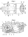
- the motor-transmission unit shown in the drawing has one an existing lower housing part 1 and an upper housing part 2 a weldable thermoplastic housing, the two housing parts being provided with flanges 3, 4 which can be put together are.
- the flange 3 facing the lower housing part 1 has centering holes 5 provided while on the flange 4 of the upper housing part 2 these centering holes 5 associated pins 6 are formed, which in the centering holes 5 inserted and after assembly and assembly the lower housing part 1 and the upper housing part 2 welded be, so that they also at the same time for the firm connection of the lower housing part 1 and upper housing part 2 serve.
- the housing 1, 2 has a receiving space 7 for an electric motor 8 provided whose electrical supply lines 9 through an opening 10 are guided into the receiving space 7.
- the motor 8 is reversible in the direction of rotation, So it can be driven in both possible directions of rotation 8 lies in the receiving space 7 against stops formed in the housing 11, is already with the insertion in the lower housing part 1 aligned in its location.
- the electric motor 8 is freely projecting from the housing 1, 2 Provide shaft 12, the free end 13 in removed from the electric motor 8 in a bearing shell 14 formed in the lower housing part 1 is supported.
- On the steel shaft 12 is an existing plastic Cylindrical worm 15 of a worm gear 16 with respect to shaft 12 rotatable, for example by a press fit.
- the helical toothing 17 of the worm 15 engages accordingly adapted teeth 18 of a worm wheel 19 that together forms the worm gear 16 with the worm 15.
- a planetary gear 20 is arranged downstream of the worm gear 16.
- the Planetary gear 20 has a one-piece design with the worm wheel 19, with this so rotatably connected sun gear 21, in the External teeth 22 three planet gears 23, only one of which is shown, engage with their corresponding external teeth 24.
- the planet gears 23 are supported on a ring gear 25, which is provided with an internal toothing 26 into which the respective External toothing 24 of the planet gears 23 engages.
- the ring gear 25 is relative to the housing 1, 2 non-rotatable, for which purpose it has projections 27 its outer circumference is provided, which in adapted recesses 28 in Intervene in housing 1, 2.
- the planet gears 23 are on journals 29 of a web lower part 30 rotatably mounted and are thereby in the same Angular distances from each other.
- the planet gears 23 are each in one piece with a gear 32 Ring gear 33 is formed.
- the external teeth of these gears 32 of the ring gear 33 engage in an internal toothing 35 of a Output ring gear 36 of the ring gear 33.
- In the gears 32 engages in each case a journal 37 of a web upper part 38.
- the lower part of the web 30 and the web upper part 38 are by means of the web lower part 30 trained receiving openings 39 and engaging in these, on the web top 38 trained connecting pin 40 together to form a housing-like Bridge connected to each other.
- the output ring gear 36 has an integrally formed with it cylindrical bearing section 41, the radial to the common axis of rotation 42 of the worm wheel 19, the planetary gear 20 and the ring gear 33 is mounted in a bearing shell 43 which is on the upper housing part 3 is trained.
- the output ring gear 36 is further in the direction of the axis of rotation 42 relative to the upper housing part 2 by itself radially to the axis of rotation 42 extending stop surfaces 44, 45 set the rotation of the Output ring gear 36 does not hinder, but the game, i.e. the movability of the ring gear 36 in the direction of the axis of rotation 42, approximately Limit 0.1 mm.
- the worm gear 16, the planetary gear 20 and the ring gear 33 form a reduction gear.
- the worm wheel 19 is on a continuous cylindrical axis 46 made of steel, one end of which in a receptacle 47 in the lower housing part 1 with a press fit, i.e. non-rotatable relative to the lower housing part 1, is held.
- the other end of the axis 46 is in one to the axis of rotation 42 concentric, cylindrical recess 48 of the output ring gear 36 supported radially to the axis of rotation 42 largely without play, but the non-rotatable axis 46 does not hinder the rotation of the output ring gear 46.
- the worm wheel 19 is freely rotatable on the axis 46 and in the direction of the axis of rotation 42 against the end face 49 of the receptacle 47 in Supported towards the lower housing part 1.
- Towards the output ring gear 36 it is axially supported on the ring gear 25 of the planetary gear 20.
- the entire output ring gear made of metal, such as cast zinc 36 has an adjoining the bearing section 41 in the substantially cylindrical output section 50, the at least one, but preferably two diametrically opposite to the axis of rotation 42 has longitudinal grooves 51 running parallel to the axis of rotation 42.
- a friction ring 52 of a slip clutch 53 is arranged, which engages with a projection 54 in the longitudinal grooves 51, whereby a rotationally fixed connection between the output ring gear 36 and the friction ring 52 is produced.
- the friction ring 52 lies against an annular collar 55 at the transition from the bearing section 41 to the driven section 51 in Direction of the axis of rotation 42 on. It forms the one already mentioned above Stop surface 45.
- the output section 50 is surrounded by an output pivoting part 56, which has a recess 57 running parallel to the axis of rotation 42, in which a bolt, not shown, of a part to be pivoted can intervene.
- the output pivoting part 56 has a friction surface 58, which rests on a friction surface 59 of the friction ring 52. Both friction surfaces 58, 59 are frustoconical and taper from the top of the housing 2 way under half a cone opening a. There is 7 ° ⁇ a ⁇ 15 ° and preferably a ⁇ 10 °.
- the output pivot part 56 is by means of a preloaded compression coil spring 60 pressed towards the friction ring 52, from the swivel part 56 and the friction ring 52, only the friction surfaces 58, 59 lie against one another.
- the above-mentioned slip clutch 53 is therefore between these two parts formed, the slip moment by the coefficient of friction between the friction surface 59 of the friction ring 52 and the friction surface 58 of the pivoting part 56 and through the normal - i.e. perpendicular - to the friction surfaces 58, 59 acting force and the average diameter d of the friction surface 58, 59 determined becomes.
- the one acting between the friction surfaces 58, 59 perpendicular to them Force is at a predetermined force of the compression spring 60 in the direction of the axis of rotation 42, the smaller the half the cone opening angle a of the friction surfaces 58, 59.
- the perpendicular to the friction surfaces 58, 59 between these forces is definitely a multiple larger, that is, the force of the compression spring 60.
- the Friction ring 52 made of metal, such as cast zinc, is made during the output pivoting part 56 consists of a common plastic.
- the helical compression spring 60 is interposed as a Washer 61 serving washer against the output swivel 56th on.
- This thrust washer 61 is also in the longitudinal grooves 51 by means of projections 54 rotatably fixed to the output ring gear 36. That between the Thrust washer 61 and the pivoting part 56 acting friction torque is at least by the quotient 10 less than the slip torque of the slip clutch 53.
- the compression spring 60 is also in the region of the free end 64 of the output section 50 against another ring disk serving as abutment 62 to that with the output section 50 by means of a bayonet lock 63 is locked.
- the two washers are made of metal, for example steel. They are identical and have the Longitudinal grooves 51 adapted projections 54 which are identical in cross section the projections 54 on the friction ring 52.
- each partial circumferential groove 65 is thus at one end 66 to form a longitudinal groove 51 open. In contrast, it is at the other end 67 to the other Longitudinal groove 51 closed.
- Each partial circumferential groove 65 has one for free End 64 directed towards recess 68 on the projections 54 correspond to the abutment washer 62.
- All gears with the exception of the output ring gear 36, consist of Plastic and are about the axis of rotation 42 or an axis parallel thereto rotatable.
- the assembly proceeds in such a way that the electric motor 8 in the Receiving space 7 inserted in the lower housing part 1 and the lines 9 can be led out through the opening 10.
- the free end 13 of the already with the screw 15 provided shaft 12 is in the bearing shell 14 used.
- the worm wheel 19 of the planetary gear 20 is on the axis pushed on until it rests against the front 49 of the receptacle 47 is coming. Subsequently, the ring gear 25 of the planetary gear 20 pushed onto the axis.
- the pin 6 of the upper housing part 2 engage in the centering holes 5 of the lower housing part 1 and are welded to it, for example by ultrasound.
- the Output ring gear 36 is now with its bearing section 41 in the bearing shell 43 of the upper housing part 2 is mounted radially.
- the friction ring 52 of the slip clutch 53 on the output section 50 pushed on and then the output swivel part 56 placed so that the two friction surfaces 58, 59 lie against one another.
- the thrust washer 61 pushed onto the output section 50 and the helical compression spring 60 also placed on the output section 50.
- the abutment washer 62 then becomes the helical compression spring 60 biased towards the friction ring 52 and the abutment washer 62 by means of the bayonet catch 63 with the driven gate 50 locked.
- the abutment washer 62 is pressed together the compression spring 60 onto the free end 64 of the output section 50 pushed on and rotated after reaching the partial circumferential grooves 65 in such a way that the projections 54 get into these partial circumferential grooves 65 and until it stops at the closed end 67. If now the Abutment washer 62 is relieved, it is so far towards free end 64 pushed back until their projections 54 in the recesses 68 come to the plant. In these recesses 68 is then Abutment washer 62 cannot be rotated relative to the driven section 50, can not be solved by turning only regardless of the direction in which the output section 50 with the Output pivot part 56 is rotated about the axis of rotation 42.
- the fully assembled motor-gear unit can be attached to the housing 1, 2 trained mounting holes 69 for a corresponding use to be assembled.
- Such an application takes place, for example, in exterior mirrors of motor vehicles, in particular in exterior mirrors for Trucks provided.
Landscapes
- Engineering & Computer Science (AREA)
- General Engineering & Computer Science (AREA)
- Mechanical Engineering (AREA)
- Power Engineering (AREA)
- Multimedia (AREA)
- Gear Transmission (AREA)
- Toys (AREA)
- Transmission Devices (AREA)
Claims (6)
- Unité de transmissioncaractériséea) avec un carter formé d'une première partie de carter (1) et d'une deuxième partie de carter (2),b) avec un engrenage à vis sans fin (16) qui comporteune vis sans fin (15) pouvant être entraínée par un moteur électrique (8) etune roue tangente (19) montée de manière à pouvoir tourner autour d'un axe de rotation (42) dans la première partie de carter (1),c) avec un engrenage planétaire (20) agencé de façon concentrique par rapport à l'axe de rotation (42) et couplé en liaison d'entraínement à la roue tangente (19) etd) avec une sortie (50, 41, 36) montée dans la deuxième partie de carter (2), agencée de façon concentrique par rapport à l'axe de rotation (42) et couplée en liaison d'entraínement à l'engrenage planétaire (20),e) dans laquelle il est prévu un axe globalement cylindrique (46) dont la première extrémité est montée dans la première partie de carter (1) et dont la deuxième extrémité est montée dans la sortie (50, 41, 36), à chaque fois radialement par rapport à l'axe de rotation (42), etf) dans laquelle la roue tangente (19) est montée de manière à pouvoir tourner librement sur l'axe (46),g) en ce que la première extrémité de l'axe (46) est fixée dans un logement en forme de manchon (47) de la première partie de carter (1) avec ajustage serré axialement et radialement par rapport à l'axe de rotation (42),h) en ce que la sortie (50, 41, 36) est formée, vue en direction axiale, d'un élément (36) de l'engrenage planétaire (20), d'un tronçon de palier cylindrique (41) et d'un tronçon de sortie (50), eti) en ce que la deuxième extrémité de l'axe (46) est montée dans le tronçon de palier cylindrique (41) qui est monté dans une coquille de coussinet (43) de la deuxième partie de carter (2) radialement par rapport à l'axe de rotation (42).
- Unité de transmission selon la revendication 1, caractérisée en ce que l'axe (46) est en métal, notamment en acier.
- Unité de transmission selon l'une des revendications 1 ou 2, caractérisée en ce que la deuxième extrémité de l'axe (46) est montée dans un évidement (48) du tronçon de palier cylindrique (41).
- Unité de transmission selon l'une des revendications 1 à 3, caractérisée en ce que l'élément (36) de l'engrenage planétaire est monté, fixe dans la direction de l'axe de rotation (42), sur la coquille de coussinet (43).
- Unité de transmission selon l'une des revendications 1 à 4, caractérisée en ce que l'élément (36) de l'engrenage planétaire est conçu comme une couronne de train planétaire de sortie (36) d'une transmission à couronne (33) couplée en liaison d'entraínement à l'engrenage planétaire (20).
- Unité de transmission selon l'une des revendications 1 à 5, caractérisée en ce que la vis sans fin (15) est fixée sur un arbre (12) dont l'extrémité libre (13) éloignée d'un moteur électrique (8) est appuyée dans une coquille de coussinet (14) de la première partie de carter (1).
Applications Claiming Priority (2)
| Application Number | Priority Date | Filing Date | Title |
|---|---|---|---|
| DE19615007 | 1996-04-16 | ||
| DE19615007A DE19615007A1 (de) | 1996-04-16 | 1996-04-16 | Getriebe-Einheit |
Publications (3)
| Publication Number | Publication Date |
|---|---|
| EP0802348A2 EP0802348A2 (fr) | 1997-10-22 |
| EP0802348A3 EP0802348A3 (fr) | 1998-04-29 |
| EP0802348B1 true EP0802348B1 (fr) | 2001-02-28 |
Family
ID=7791429
Family Applications (1)
| Application Number | Title | Priority Date | Filing Date |
|---|---|---|---|
| EP97104375A Expired - Lifetime EP0802348B1 (fr) | 1996-04-16 | 1997-03-14 | Ensemble de transmission |
Country Status (4)
| Country | Link |
|---|---|
| US (1) | US6007446A (fr) |
| EP (1) | EP0802348B1 (fr) |
| DE (2) | DE19615007A1 (fr) |
| MX (1) | MX9702766A (fr) |
Families Citing this family (15)
| Publication number | Priority date | Publication date | Assignee | Title |
|---|---|---|---|---|
| DE29904028U1 (de) | 1999-03-05 | 1999-09-02 | Klann Tools Ltd | Sicherheitsspindelkopf für Spindelantriebe |
| DE20105791U1 (de) | 2001-04-03 | 2002-08-14 | MEKRA Lang GmbH & Co. KG, 90765 Fürth | Spiegelanordnung für Kraftfahrzeuge |
| DE10148611B4 (de) | 2001-10-02 | 2005-01-27 | Mekra Lang Gmbh & Co. Kg | Vorrichtung zum schwenkbeweglichen Lagern eines Tragarms für einen Aussenspiegel |
| GB0204820D0 (en) * | 2002-03-01 | 2002-04-17 | Standen John P | Gear mechanism for use in controlling vehicle rear-view mirrors and measuring angular deflection of an articulated trailer relative to the tractor |
| US20050054471A1 (en) * | 2003-09-08 | 2005-03-10 | Yakov Fleytman | Drive axle assembly and differential |
| JP2005091826A (ja) * | 2003-09-18 | 2005-04-07 | Fuji Xerox Co Ltd | 画像形成装置、画像形成装置の駆動機構、およびウォームギア組の製造方法 |
| DE10346403B4 (de) * | 2003-10-07 | 2007-05-10 | Pierburg Gmbh | Stellvorrichtung |
| MX2015010929A (es) * | 2013-02-22 | 2017-05-01 | Magna powertrain gmbh & co kg | Carcasa para caja de cambios y metodos para producir una carcasa para caja de cambios. |
| WO2014205217A1 (fr) * | 2013-06-19 | 2014-12-24 | Magna International Inc. | Actionneur étanche avec embrayage interne |
| CA2939278C (fr) | 2014-03-21 | 2020-10-27 | Magna International Inc. | Systeme de panneau lateral aerodynamique deployable |
| WO2015143267A1 (fr) | 2014-03-21 | 2015-09-24 | Magna International Inc. | Système de couvercle de benne aérodynamique déployable |
| CN110450863B (zh) | 2014-06-11 | 2022-09-16 | 麦格纳外饰公司 | 用于车辆的连杆组件 |
| US9956998B2 (en) | 2014-06-11 | 2018-05-01 | Magna Exteriors Inc. | Active front deflector |
| JP6618415B2 (ja) * | 2016-04-08 | 2019-12-11 | 株式会社東海理化電機製作所 | 車両用視認装置 |
| DE102017129186B4 (de) * | 2017-12-07 | 2021-07-01 | Motherson Innovations Company Limited | Rückblickvorrichtung für ein Kraftfahrzeug, Montageverfahren dafür und Kraftfahrzeug mit einer Rückblickvorrichtung |
Family Cites Families (24)
| Publication number | Priority date | Publication date | Assignee | Title |
|---|---|---|---|---|
| DE7627888U1 (fr) * | 1900-01-01 | Julius Bauser Kg, Kontrolluhrenfabrik, 7241 Empfingen | ||
| US3265362A (en) * | 1964-03-02 | 1966-08-09 | Warren E Moody | Hoisting devices |
| JPS6047130B2 (ja) * | 1975-08-14 | 1985-10-19 | 市光工業株式会社 | 栗両用後写鏡 |
| US4133344A (en) * | 1976-06-10 | 1979-01-09 | The Toro Company | Power transmission for self-propelled irrigation system |
| DE2820541C2 (de) * | 1978-05-11 | 1986-10-09 | Bernhard Dipl.-Wirtsch.-Ing. 3002 Wedemark Mittelhäuser | Außenrückblickspiegel für Kraftfahrzeuge |
| DE2846586A1 (de) * | 1978-10-26 | 1980-05-08 | Kienzle Uhrenfabriken Gmbh | Verstellvorrichtung fuer kfz-aussenrueckblickspiegel |
| DE3013009A1 (de) * | 1980-04-03 | 1981-10-08 | Gustav Magenwirth Gmbh & Co, 7432 Urach | Vorrichtung zum antrieb eines kraftfahrzeugspiegels |
| DE3434905A1 (de) * | 1984-09-22 | 1986-04-03 | SWF Auto-Electric GmbH, 7120 Bietigheim-Bissingen | Antriebseinheit, insbesondere zum verstellen von fensterscheiben, schiebedaechern, sitzen und aehnlichen kraftfahrzeugteilen |
| EP0209666B1 (fr) * | 1985-05-21 | 1990-03-14 | Aisin Seiki Kabushiki Kaisha | Moyens de réglage de position angulaire |
| US4641887A (en) * | 1985-09-16 | 1987-02-10 | Keiper Recaro Incorporated | Planetary seat back adjuster |
| DE3741615A1 (de) * | 1987-12-09 | 1989-06-22 | Reitter & Schefenacker Kg | Elektrischer motorantrieb fuer fensterheber von kraftfahrzeugen |
| US4921083A (en) * | 1989-02-28 | 1990-05-01 | Square D Company | Clutch module with predetermined torque |
| DE3914334C2 (de) * | 1989-04-29 | 1994-08-04 | Kienzle Uhrenfabriken Gmbh | Verstellvorrichtung für einen KFZ-Außenspiegel |
| NL8902300A (nl) * | 1989-09-14 | 1991-04-02 | Iku Holding Montfoort Bv | Omklapmechanisme voor een spiegelhuis van een achteruitkijkspiegel voor een voertuig. |
| JP2515645Y2 (ja) * | 1989-11-21 | 1996-10-30 | アスモ 株式会社 | 減速機付モ−タ |
| IT220513Z2 (it) * | 1990-05-15 | 1993-09-24 | Gilardini Spa | Specchio retrovisore per un veicolo. |
| JPH0463738A (ja) * | 1990-07-04 | 1992-02-28 | Ichikoh Ind Ltd | 電動ステー格納式ミラー装置 |
| DE4119748C2 (de) * | 1991-06-15 | 1994-06-09 | Luchtenberg Gmbh & Co | Abklappbarer Rückspiegel |
| IT1252140B (it) * | 1991-11-29 | 1995-06-05 | Commer Spa | Dispositivo per la rotazione controllata di uno specchietto retrovisore esterno |
| JPH05222245A (ja) * | 1992-02-10 | 1993-08-31 | Tokai Carbon Co Ltd | ゴム組成物 |
| NL9202266A (nl) * | 1992-12-24 | 1994-07-18 | Iku Holding Montfoort Bv | Spiegelinklapmechanisme, en voertuig voorzien van een dergelijk spiegelinklapmechanisme. |
| DE4311355C2 (de) * | 1993-04-06 | 1995-01-26 | Stephan Werke Gmbh & Co | Schneckengetriebe |
| JPH07195979A (ja) * | 1993-12-28 | 1995-08-01 | Sakae Riken Kogyo Kk | 電動可倒式ミラー装置 |
| JP3323686B2 (ja) * | 1995-01-10 | 2002-09-09 | アスモ株式会社 | 移動体の位置検出装置 |
-
1996
- 1996-04-16 DE DE19615007A patent/DE19615007A1/de not_active Withdrawn
-
1997
- 1997-03-14 EP EP97104375A patent/EP0802348B1/fr not_active Expired - Lifetime
- 1997-03-14 DE DE59703027T patent/DE59703027D1/de not_active Expired - Lifetime
- 1997-04-04 US US08/832,926 patent/US6007446A/en not_active Expired - Lifetime
- 1997-04-16 MX MX9702766A patent/MX9702766A/es unknown
Also Published As
| Publication number | Publication date |
|---|---|
| MX9702766A (es) | 1998-04-30 |
| EP0802348A3 (fr) | 1998-04-29 |
| EP0802348A2 (fr) | 1997-10-22 |
| DE19615007A1 (de) | 1997-10-23 |
| DE59703027D1 (de) | 2001-04-05 |
| US6007446A (en) | 1999-12-28 |
Similar Documents
| Publication | Publication Date | Title |
|---|---|---|
| DE69919135T2 (de) | Anlasser für kraftfahrzeug mit untersetzungsgetriebe mit torsionsdämpfungformenden mitteln | |
| DE3006331C3 (de) | Getriebe | |
| DE3430067C1 (de) | Gelenkwelle | |
| EP0802348B1 (fr) | Ensemble de transmission | |
| DE3830283C2 (fr) | ||
| DE2912104C2 (de) | Befestigungsvorrichtung zwischen Antriebswelle und Zahnrad einer Zahnradpumpe | |
| DE102011075183A1 (de) | Verstellantrieb für eine Verstelleinrichtung eines Kraftfahrzeugsitzes | |
| EP1989096B1 (fr) | Engrenage hélicoïdal pour une direction à crémaillère | |
| DE19547980A1 (de) | Differentialgetriebe | |
| DE102004008538B4 (de) | Differential mit einer Bolzenbefestigungsbaugruppe | |
| EP0802084A1 (fr) | Ensemble de transmission | |
| DE3713870A1 (de) | Kreuzgelenk | |
| DE4302726C2 (de) | Zahnwellenverbindung und Verfahren zur Herstellung einer Zahnwellenverbindung | |
| DE102016104150A1 (de) | Lenkgetriebe | |
| DE69822008T2 (de) | Übertragungskupplungseinheit | |
| DE2259985A1 (de) | Anordnung zum loesbaren befestigen einer nabe oder eines rades auf einer welle | |
| DE4424988C1 (de) | Hydrodynamischer Drehmomentwandler mit einer Überbrückungskupplung | |
| DE69811191T2 (de) | Anlasser für Kraftfahrzeug mit Untersetzungsgetriebe und Stossbegrenzervorrichtung | |
| DE2613656C2 (de) | Antriebsanordnung für Nutzfahrzeuge mit Allradantrieb | |
| EP1101964A1 (fr) | Accouplement de surcharge | |
| DE68912134T2 (de) | Lagerstiftsicherung mit nockenwirkung für ein differential. | |
| EP0491221B1 (fr) | Joint articulé de transmission de couple, de préférence pour demi-arbres ou pour arbres cardan à plusieurs parties | |
| EP2640623B1 (fr) | Guide de crémaillère monté sur galets | |
| DE102017118571A1 (de) | Winkelgetriebe | |
| DE4217123C2 (de) | Rückenlehne für Fahrzeugsitze, insbesondere Kraftfahrzeugsitze |
Legal Events
| Date | Code | Title | Description |
|---|---|---|---|
| PUAI | Public reference made under article 153(3) epc to a published international application that has entered the european phase |
Free format text: ORIGINAL CODE: 0009012 |
|
| AK | Designated contracting states |
Kind code of ref document: A2 Designated state(s): DE ES FR GB IT SE |
|
| PUAL | Search report despatched |
Free format text: ORIGINAL CODE: 0009013 |
|
| AK | Designated contracting states |
Kind code of ref document: A3 Designated state(s): DE ES FR GB IT SE |
|
| 17P | Request for examination filed |
Effective date: 19980818 |
|
| 17Q | First examination report despatched |
Effective date: 20000222 |
|
| GRAG | Despatch of communication of intention to grant |
Free format text: ORIGINAL CODE: EPIDOS AGRA |
|
| GRAG | Despatch of communication of intention to grant |
Free format text: ORIGINAL CODE: EPIDOS AGRA |
|
| GRAG | Despatch of communication of intention to grant |
Free format text: ORIGINAL CODE: EPIDOS AGRA |
|
| GRAG | Despatch of communication of intention to grant |
Free format text: ORIGINAL CODE: EPIDOS AGRA |
|
| GRAH | Despatch of communication of intention to grant a patent |
Free format text: ORIGINAL CODE: EPIDOS IGRA |
|
| GRAH | Despatch of communication of intention to grant a patent |
Free format text: ORIGINAL CODE: EPIDOS IGRA |
|
| GRAA | (expected) grant |
Free format text: ORIGINAL CODE: 0009210 |
|
| AK | Designated contracting states |
Kind code of ref document: B1 Designated state(s): DE ES FR GB IT SE |
|
| PG25 | Lapsed in a contracting state [announced via postgrant information from national office to epo] |
Ref country code: SE Free format text: THE PATENT HAS BEEN ANNULLED BY A DECISION OF A NATIONAL AUTHORITY Effective date: 20010228 Ref country code: IT Free format text: LAPSE BECAUSE OF FAILURE TO SUBMIT A TRANSLATION OF THE DESCRIPTION OR TO PAY THE FEE WITHIN THE PRE;WARNING: LAPSES OF ITALIAN PATENTS WITH EFFECTIVE DATE BEFORE 2007 MAY HAVE OCCURRED AT ANY TIME BEFORE 2007. THE CORRECT EFFECTIVE DATE MAY BE DIFFERENT FROM THE ONE RECORDED.SCRIBED TIME-LIMIT Effective date: 20010228 Ref country code: GB Free format text: LAPSE BECAUSE OF FAILURE TO SUBMIT A TRANSLATION OF THE DESCRIPTION OR TO PAY THE FEE WITHIN THE PRESCRIBED TIME-LIMIT Effective date: 20010228 Ref country code: FR Free format text: LAPSE BECAUSE OF FAILURE TO SUBMIT A TRANSLATION OF THE DESCRIPTION OR TO PAY THE FEE WITHIN THE PRESCRIBED TIME-LIMIT Effective date: 20010228 Ref country code: ES Free format text: THE PATENT HAS BEEN ANNULLED BY A DECISION OF A NATIONAL AUTHORITY Effective date: 20010228 |
|
| REF | Corresponds to: |
Ref document number: 59703027 Country of ref document: DE Date of ref document: 20010405 |
|
| EN | Fr: translation not filed | ||
| GBV | Gb: ep patent (uk) treated as always having been void in accordance with gb section 77(7)/1977 [no translation filed] |
Effective date: 20010228 |
|
| PLBE | No opposition filed within time limit |
Free format text: ORIGINAL CODE: 0009261 |
|
| STAA | Information on the status of an ep patent application or granted ep patent |
Free format text: STATUS: NO OPPOSITION FILED WITHIN TIME LIMIT |
|
| 26N | No opposition filed | ||
| PGFP | Annual fee paid to national office [announced via postgrant information from national office to epo] |
Ref country code: DE Payment date: 20160520 Year of fee payment: 20 |
|
| REG | Reference to a national code |
Ref country code: DE Ref legal event code: R071 Ref document number: 59703027 Country of ref document: DE |