EP0802526B1 - Speichervorrichtung - Google Patents
Speichervorrichtung Download PDFInfo
- Publication number
- EP0802526B1 EP0802526B1 EP97302206A EP97302206A EP0802526B1 EP 0802526 B1 EP0802526 B1 EP 0802526B1 EP 97302206 A EP97302206 A EP 97302206A EP 97302206 A EP97302206 A EP 97302206A EP 0802526 B1 EP0802526 B1 EP 0802526B1
- Authority
- EP
- European Patent Office
- Prior art keywords
- seek
- disk
- data storage
- stop
- start operation
- Prior art date
- Legal status (The legal status is an assumption and is not a legal conclusion. Google has not performed a legal analysis and makes no representation as to the accuracy of the status listed.)
- Expired - Lifetime
Links
Images


Classifications
-
- G—PHYSICS
- G11—INFORMATION STORAGE
- G11B—INFORMATION STORAGE BASED ON RELATIVE MOVEMENT BETWEEN RECORD CARRIER AND TRANSDUCER
- G11B5/00—Recording by magnetisation or demagnetisation of a record carrier; Reproducing by magnetic means; Record carriers therefor
- G11B5/41—Cleaning of heads
-
- A—HUMAN NECESSITIES
- A61—MEDICAL OR VETERINARY SCIENCE; HYGIENE
- A61K—PREPARATIONS FOR MEDICAL, DENTAL OR TOILETRY PURPOSES
- A61K38/00—Medicinal preparations containing peptides
- A61K38/16—Peptides having more than 20 amino acids; Gastrins; Somatostatins; Melanotropins; Derivatives thereof
- A61K38/17—Peptides having more than 20 amino acids; Gastrins; Somatostatins; Melanotropins; Derivatives thereof from animals; from humans
-
- C—CHEMISTRY; METALLURGY
- C07—ORGANIC CHEMISTRY
- C07K—PEPTIDES
- C07K14/00—Peptides having more than 20 amino acids; Gastrins; Somatostatins; Melanotropins; Derivatives thereof
- C07K14/435—Peptides having more than 20 amino acids; Gastrins; Somatostatins; Melanotropins; Derivatives thereof from animals; from humans
- C07K14/705—Receptors; Cell surface antigens; Cell surface determinants
- C07K14/715—Receptors; Cell surface antigens; Cell surface determinants for cytokines; for lymphokines; for interferons
-
- C—CHEMISTRY; METALLURGY
- C12—BIOCHEMISTRY; BEER; SPIRITS; WINE; VINEGAR; MICROBIOLOGY; ENZYMOLOGY; MUTATION OR GENETIC ENGINEERING
- C12N—MICROORGANISMS OR ENZYMES; COMPOSITIONS THEREOF; PROPAGATING, PRESERVING, OR MAINTAINING MICROORGANISMS; MUTATION OR GENETIC ENGINEERING; CULTURE MEDIA
- C12N5/00—Undifferentiated human, animal or plant cells, e.g. cell lines; Tissues; Cultivation or maintenance thereof; Culture media therefor
- C12N5/10—Cells modified by introduction of foreign genetic material
-
- C—CHEMISTRY; METALLURGY
- C12—BIOCHEMISTRY; BEER; SPIRITS; WINE; VINEGAR; MICROBIOLOGY; ENZYMOLOGY; MUTATION OR GENETIC ENGINEERING
- C12Q—MEASURING OR TESTING PROCESSES INVOLVING ENZYMES, NUCLEIC ACIDS OR MICROORGANISMS; COMPOSITIONS OR TEST PAPERS THEREFOR; PROCESSES OF PREPARING SUCH COMPOSITIONS; CONDITION-RESPONSIVE CONTROL IN MICROBIOLOGICAL OR ENZYMOLOGICAL PROCESSES
- C12Q1/00—Measuring or testing processes involving enzymes, nucleic acids or microorganisms; Compositions therefor; Processes of preparing such compositions
- C12Q1/68—Measuring or testing processes involving enzymes, nucleic acids or microorganisms; Compositions therefor; Processes of preparing such compositions involving nucleic acids
-
- G—PHYSICS
- G01—MEASURING; TESTING
- G01N—INVESTIGATING OR ANALYSING MATERIALS BY DETERMINING THEIR CHEMICAL OR PHYSICAL PROPERTIES
- G01N33/00—Investigating or analysing materials by specific methods not covered by groups G01N1/00 - G01N31/00
- G01N33/48—Biological material, e.g. blood, urine; Haemocytometers
- G01N33/50—Chemical analysis of biological material, e.g. blood, urine; Testing involving biospecific ligand binding methods; Immunological testing
-
- G—PHYSICS
- G11—INFORMATION STORAGE
- G11B—INFORMATION STORAGE BASED ON RELATIVE MOVEMENT BETWEEN RECORD CARRIER AND TRANSDUCER
- G11B19/00—Driving, starting, stopping record carriers not specifically of filamentary or web form, or of supports therefor; Control thereof; Control of operating function ; Driving both disc and head
- G11B19/02—Control of operating function, e.g. switching from recording to reproducing
- G11B19/04—Arrangements for preventing, inhibiting, or warning against double recording on the same blank or against other recording or reproducing malfunctions
-
- G—PHYSICS
- G11—INFORMATION STORAGE
- G11B—INFORMATION STORAGE BASED ON RELATIVE MOVEMENT BETWEEN RECORD CARRIER AND TRANSDUCER
- G11B23/00—Record carriers not specific to the method of recording or reproducing; Accessories, e.g. containers, specially adapted for co-operation with the recording or reproducing apparatus ; Intermediate mediums; Apparatus or processes specially adapted for their manufacture
- G11B23/50—Reconditioning of record carriers; Cleaning of record carriers ; Carrying-off electrostatic charges
- G11B23/505—Reconditioning of record carriers; Cleaning of record carriers ; Carrying-off electrostatic charges of disk carriers
-
- G—PHYSICS
- G11—INFORMATION STORAGE
- G11B—INFORMATION STORAGE BASED ON RELATIVE MOVEMENT BETWEEN RECORD CARRIER AND TRANSDUCER
- G11B5/00—Recording by magnetisation or demagnetisation of a record carrier; Reproducing by magnetic means; Record carriers therefor
- G11B5/48—Disposition or mounting of heads or head supports relative to record carriers ; arrangements of heads, e.g. for scanning the record carrier to increase the relative speed
- G11B5/54—Disposition or mounting of heads or head supports relative to record carriers ; arrangements of heads, e.g. for scanning the record carrier to increase the relative speed with provision for moving the head into or out of its operative position or across tracks
- G11B5/55—Track change, selection or acquisition by displacement of the head
- G11B5/5521—Track change, selection or acquisition by displacement of the head across disk tracks
- G11B5/5526—Control therefor; circuits, track configurations or relative disposition of servo-information transducers and servo-information tracks for control thereof
- G11B5/553—Details
- G11B5/5547—"Seek" control and circuits therefor
Definitions
- This invention relates generally to direct access storage devices which may be used in applications, such as computers. More specifically, the invention relates to assemblies and methods for improving the reliability of direct access storage devices that are used in computers.
- Disk drives are an integral part of most computing devices. Disk drives, whether based on magnetic or optical storage technologies, are frequently used in computing systems to provide rapid, random access to stored data. Over the years disk drive technology has progressed to a point where a massive amount of data may now be stored in a disk drive device using small diameter, non-removable disks.
- the disk drive units typically include a rigid disk on which a magnetic medium is provided.
- a protective overcoat is applied to the magnetic medium which is typically carbon or zirconia with a thin coating of liquid or solid lubricant such as polyperfluoroether.
- a slider supports one or more transducer heads and is mounted to an arm suspended from a pivot point over the disk.
- the air bearing is created by the aerodynamic properties of the slider as it encounters air pressure resulting from by the high speed rotation of the disk (3600-7200 rpm).
- air is the primary lubricant while the transducer is flying.
- failure of the slider to maintain head-disk separation can result in excessive contact between the head and disk or a head crash.
- a head crash may result from any series of events.
- Sliders may use a negative pressure airbearing. In this case the slider often acts as a vacuum cleaner. Materials on the disks can be picked up and retained in the negative pressure cavity of these sliders. For more traditional positive pressure sliders, debris often accumulates on the leading-edge tapers and airbearing rails. These collection points are also seen for negative pressure sliders. Thus as disks collect materials, the sliders sweeping over them collect this material.
- the system may start off with the slider flying or in limited contact with the disk. If the slider then picks up some debris, the debris will either drag over the disk or alter the air bearing such that the slider flies lower. Debris may continue to collect on the head and slider as it flies at lower and lower spacings. Eventually, the slider begins to contact the disk continuously using up the liquid or solid lubricant, wearing through the carbon overcoat, and damaging the magnetic medium. This will roughen the disk surface making even partial flying over the affected tracks difficult, resulting in an inability to read and write data.
- McNeil U.S. Patent No. 4,384,311 teaches a method for cleaning the magnetic disk surfaces and the heads.
- the heads are loaded and caused to fly on the disc surfaces.
- the spindle motor speed is reduced to a speed where the heads fly at approximately 50% of the normal flying height and the head support structure drive motor is commanded to sweep the heads across the disc surfaces, forward and reverse. This is intended to remove any particles down to an elevation that is 50% of the normal flying height.
- the same operation is completed with a spindle speed creating 25% of normal flying height.
- Komiyama, JP Appl. No.03-110045 teaches a method for cleaning an unstoppable system by stopping and restarting the rotation of the disk after shifting the magnetic head to a cleaning area on a disk.
- JP Appl. No.3-31260 teaches a method to prevent dust from sticking to a magnetic head in a magnetic disk device.
- a spindle motor control circuit repeats a motor start/stop operation during operation of the drive.
- Ishihara, JP Appl. No.4-67351 teaches a method for removing fine dust and improving reliability by which a stop operation and a start operation are continuously executed in a disk drive.
- JP-A-02249172 discloses a method and apparatus for cleaning a head in a floppy disk drive based upon the number of times the head is loaded onto the medium.
- EP-A-0429079 discloses a data storage device provided with a self cleaning function based upon the number of read writes performed.
- a data storage device comprising: a memory element disk rotatably mounted about an axis; an actuator, for moving a transducer head relative to said disk; a disk drive controller for effecting disk stop/start operations characterised by: a counter for counting the number of seek operations performed by said actuator since a disk stop/start operation has occurred; means for initiating another said stop/start operation based on the count of said counter.
- a method of increasing the reliability of a data storage device comprising a memory element disk containing data rotatably mounted about an axis, a transducer head, and actuator for moving said transducer head relative to said disk, and a counter for counting the number of seek operations performed by said transducer head
- said method comprising the steps of: (a) defining a threshold seek operation count T seek ; (b) counting the number of seek operations since the last stop/start operation to determine V seek ; (c) determining whether V seek or a function of V seek (D seek ) is equal to or greater than T seek ; and (d) performing another stop/start operation when V seek or the function of V seek (D seek ) is equal to or greater than T seek .
- the invention may be executed in a data storage device having a disk rotatably mounted about an axis, and an actuator for moving a transducer head relative to the disk.
- the device generally also has a counter for counting the number of seek operations performed by the actuator since a stop/start operation has occurred, and means for initiating another stop/start operation when the count of the counter reaches a predetermined number.
- the data storage device also may have a non-volatile random access memory for temporarily storing read/write data. The read/write data is sent to the auxiliary memory by the data storage device while the stop/start operation is performed.
- the invention may also be executed with an array controller which controls a plurality of data storage devices.
- the invention bases the stop and restart operations on the number of seeks operations that have occurred and the power-on-hours since the last stop/start operation. If a critical number of seeks has occurred over a certain length of time, then a drive is stopped and then immediately restarted.
- the purpose of the start/stop operation is to remove excessive materials from the sliders and transfer these to the landing zone.
- the invention is also applicable to disk drive arrays. Although disk drive arrays often can tolerate a drive failure, system performance suffers while a drive is being replaced and while the data on the new drive is reconstructed. In file server applications, for instance, rapid count T seek , counting the number of seek operations since the last stop/start operation to determine M seek , recalling the total number of seek operations completed by the data storage device to define N seek , defining D seek by determining the difference between N seek and M seek , and determining whether D seek is greater than T seek .
- a method of increasing the reliability of an array of data storage devices includes defining threshold seek operation count T seek for each drive of the array, counting the number of seek operations since the last/stop start operation to determine M seek , recalling the total number of seek operations completed by the data storage device to define N seek , defining D seek by determining the difference between N seek and M seek , and determining whether D seek is greater than T seek .
- the invention may be executed in a data storage device having a disk rotatably mounted about an axis, and an actuator for moving a transducer head relative to the disk.
- the device generally also has a counter for counting the number of seek operations performed by the actuator since a stop/start operation has occurred, and means for initiating another stop/start operation when the count of the counter reaches a predetermined number.
- the data storage device also may have a non-volatile random access memory for temporarily storing read/write data. The read/write data is sent to the auxiliary memory by the data storage device while the stop/start operation is performed.
- the invention may also be executed with an array controller which controls a plurality of data storage devices.
- the invention bases the stop and restart operations on the number of seeks operations that have occurred and the power-on-hours since the last stop/start operation. If a critical number of seeks has occurred over a certain length of time, then a drive is stopped and then immediately restarted.
- the purpose of the start/stop operation is to remove excessive materials from the sliders and transfer these to the landing zone.
- the invention is also applicable to disk drive arrays.
- disk drive arrays often can tolerate a drive failure, system performance suffers while a drive is being replaced and while the data on the new drive is reconstructed.
- file server applications for instance, rapid data availability is of paramount importance.
- These servers provide storage for multiple users where the data demand is synchronous.
- Multiple disk drives are connected to a controller which emulates a single virtual drive.
- the independent disk drives are not seen as an individual disk drives.
- a redundant disk array one or more simultaneous drive failures can occur without losing any data.
- This invention is suitable for arrays that may sustain one or more drive failures.
- a drive becomes inoperable, all user data continues to be available because of the redundancy found in the array. If the array uses distributed parity, for example, data on the failing drive can be reconstructed by combining the parity and data on one or more of the other drives.
- a non-volatile memory is often included to assist in the transfer of data to and from the individual drives. If the non-volatile memory is used as a write cache, then data to be written is temporarily stored to increase efficiency.
- non-volatile means that the memory does not fail for lack of power; either by catastrophic unintended loss of power or an intended power down by stop/start operation. If the array suddenly loses power, the non-volatile nature of this memory ensures that data that was being written at the start of the power failure is not lost.
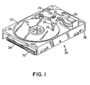
- FIGURE 1 is a perspective illustration of an exemplary data storage device which may be used with the invention.
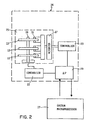
- FIGURE 2 is a schematic illustration of a disk drive enclosure which may be used with the invention.
- FIGURE 3 is a schematic illustration of an exemplary seek operation undertaken by a disk drive assembly such as that depicted in Figure 1.
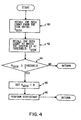
- FIGURE 4 is a schematic illustration of one embodiment of the invention.
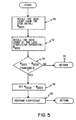
- FIGURE 5 is a schematic illustration of an alternative embodiment of the invention.
- FIGURE 6 is a schematic illustration of a computer system which is supported by auxiliary memory.
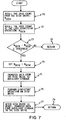
- FIGURE 7 is a schematic illustration of an alternative embodiment of the invention.
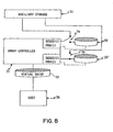
- FIGURE 8 is a schematic illustration depicting application of the invention to an exemplary array system.
- the invention comprises methods and assemblies for increasing the reliability of a data storage device.
- Storage devices in which the method of the invention may be used generally comprise a memory element disk, containing data, the disk being rotatably mounted about an axis, and a transducer positioned to read and/or write data from/to the disk.
- the device also contains an actuator for moving the transducer head relative to the disk, and a counter for counting the number of seek operations performed by the transducer head.
- Figure 1 provides a perspective view of an illustrative data storage device or head disk assembly incorporating the teachings of the invention.
- the assembly 10 includes a disk 12 on which a magnetic medium is disposed.
- the disk 12 is rotated at high speeds about a spindle motor assembly 14.
- a magnetic transducer or head 16 is suspended over the disk at the end of a load beam 18.
- the head 16 and load beam 18 are suspended at the proximal end of an arm 20.
- the distal end of the arm 20 provides an armature within a voice coil actuator motor 24.
- the actuator motor 24 induces moments in the arm 20 about a pivot point 22 and thereby moves the head 16 in a general radial direction over the disk 12.
- the assembly is mounted within a frame 26 or disk drive enclosure.
- Spindle motor assembly 14, motor 24, as well as the head 16 are activated by a host system through an electronic circuit disposed on a circuit board. Electrical interconnect between the board and the host system is effected via a receptacles
- a stack multiple head disk assemblies are stacked within a single unit.
- the magnetic medium on the disk 12 is organized into cylinders, data tracks within the cylinders and sectors within the data tracks.
- An individual cylinder may be thought of as the same head location on more than one disk for a given movement of the load beam actuator.
- Data is written to and read from the radially spaced tracks by the transducer head 16.
- the position of the head relative to a particular track on the disk is maintained by a servo-control unit in a conventional manner.
- the load beam 18 is lightly biased against the aerodynamic lift of the slider so that the head 16 flies on an air bearing over the disk 12 when the disk 12 is rotated at a highspeed by the spindle motor assembly 14.
- digital data is stored in the form of magnetic transitions on a series of spiral tracks or concentric, closely spaced tracks comprising the surface of the magnetizable rigid data storage disks.
- the tracks are generally divided into a plurality of sectors, with each sector comprising a number of information fields.
- One of the information fields is typically designated for storing data, while other fields contain sector identification and synchronization information, for example.
- Data is transferred to, and retrieved from, specified track and sector locations by the transducers being shifted from track to track, typically under the control of a controller.
- the transducer assembly typically includes a read element and a write element.
- Other transducer assembly configurations incorporate a single transducer element used to both write data to the disks and read data from the disks.
- Writing data to a data storage disk generally involves passing a current through the write element of the transducer assembly to produce magnetic lines of flux which magnetize a specific location of the disk surface. Reading data from a specified disk location is typically accomplished by a read element of the transducer assembly sensing the magnetic field or flux lines emanating from the magnetized locations of the disk. As the read element passes over the rotating disk surface, the interaction between the read element and the magnetized locations on the disk surface results in the production of electrical signals in the read element. The electrical signals correspond to transitions in the magnetic field.
- a seek is the movement of the head radially across the disk.
- the head moves radially on a periodic basis either in routine idle, to avoid depletion of lubricant, or in reading and writing applications.
- the hard drive is composed of a number of different constituent parts.
- a disk enclosure 25 within which are the hard drive memory elements 12.
- the memory elements 12 generally rotate above a spindle motor assembly 14.
- the heads 16 are controlled by an actuator 17.
- a microprocessor 19 controls the disk enclosure environment signalling a first controller 21 which controls the spindle motor assembly 14 as well as a second controller 23 which directs the actuator 17 rotating the disk drive heads 16.
- the method of the invention may be configured in any number of different environments consistent with the invention.
- a counting program may generally be found in the microprocessor 19 for counting the number of seek operations undertaken by the head over any given period of time.
- the microprocessor 19 controls movement of the head and, in turn, is controlled by the computer system microprocessor 27, for example, on the computer system mother board.
- any drive assembly, stack of assemblies, or array of drive assemblies is supported by various control procedures found on the operational memory in one or more of the computer system microprocessor 27, disk drive microprocessor 19, disk 12 or other memory elements of the disk drive 10.
- the operational memory including the counting program may be programmed into any of these elements within the system. These control procedures are used to assist the drive in coming ready to operate and initiating the use of variety of applications.
- the computer system which includes the direct access storage device, generally comprises programming which counts individual seek operations as part of this operational memory.
- Each seek operation moves the head 16 over a new disk area.
- the head starts movement in a relationship to the disk 12. Since the disk 12 is constantly rotating, the movement of the head 16, while essentially radial is in a spiral pattern in relationship to the disk 12.
- the head 16 moves outward, radially, to point T2.
- the drive may not start. The conditions may worsen at elevated temperatures.
- the accumulated material on the slider forms a bond with the disks and this creates a force which is many times what a drive motor can provide.
- the method of the invention is initiated by programming the computer system to count the number of seek operations and recall the seek operations undertaken to compare these against a threshold count.
- programming may be completed in any of the system elements which contain the system's operational memory.
- the operational memory is programmed to count and recall the seeks completed by the drive head across the surface of the disk STEP 40.
- the varying seek count, V seek is initially set at zero and seeks are counted from activation of the system, but once a stop/start operation is performed, the varying seek count, V seek , is reset to zero and seeks are counted from the last stop/start operation.
- the operational memory also recalls the seek count at which the drive is at threshold, T seek , STEP 42.
- T seek is used to evaluate the need for stop/start operations as it provides a true indication of actual hard drive use; the movement of the head 16 across the hard disk element 12.
- T seek may be set at any value which reflects the size and usage level of the computer system. For example, a single drive computer system may have usage at a different level than computer system having an array of more than one drive. Further, personal computer systems may receive different levels of usage when compared to computer systems used by institutions.
- This varying seek count, V seek is compared to the threshold seek count T seek , STEP 44, and when: V seek ⁇ T seek a stop/start operation is initiated, STEP 48. V seek may then be reset to zero so that once-the stop/start operation is completed, the seek count may resume, STEP 46.
- An alternative means of executing the invention is to use a counter which counts the number of seeks undertaken by the system from the initial activation of the system. Once reviewed, if the number of seek operations completed meets or exceeds a threshold level, T seek , a stop/start operation is undertaken, and the counting operation is reset.
- the operational memory may be programmed to recall the threshold number of seeks, T seek , which must be undertaken before a stop/start operation is undertaken.
- the operational memory of the computer system may then be programmed to count and recall N seek , STEP 50, to determine whether the seek operation parameter identified as T seek has been met. This operation is initiated by determining the total number of seeks which the computer system has completed since beginning operation, N seek .
- Stop/start operations may occur, for example, with the first use of the computer system, routine trouble shooting operations which occur as the computer system is brought into full operational capability, or with the powering down of the computer system at the termination of routine use.
- the operational memory compares these two parameters to determine whether a stop/start operation should be undertaken, STEP 54.
- auxiliary memory (or storage) 31 may be available within the computer system.
- Auxiliary memory 31 is often used to maintain the computer system microprocessor 27 operation in environments with high user volume such as administrative or service operations in financial, communications, or governmental institutions.
- Auxiliary storage or memory may be an element separate from the computer system or encompassed within the computer system itself.
- Auxiliary storage may comprise a non-volatile or fault tolerant storage, such as an added disk drive, additional random access memory, or flash memory, i.e. electronically erasable programmable read only memory.
- FIG 7 the system of the invention for use with a computer comprising auxiliary memory storage may be seen.
- auxiliary storage When auxiliary storage is present, the system proceeds through the same steps depicted in Figure 5. However, the operational memory of the computer system, transfers the data of interest to the auxiliary storage when the condition set by equation 3 above is met. The stop/start operation is then completed. After the hard drive element is powered back up the data is transferred back onto the hard disk element.
- the operational memory of the computer system is programmed to count and recall the number of seek operations undertaken since initiation of system operation N seek , STEP 70 (see Fig. 7).
- the system is also programmed to count and recall M seek , that is the number of seek operations undertaken since the last stop/start operation, STEP 72.
- N seek and M seek are compared, STEP 73, and when the condition of equation 2 is met, seek counting continues, STEP 78.
- M seek is reset to equal N seek , STEP 74.
- Data is then transferred from the virtual drive to the auxiliary storage by the array controller, STEP 75.
- a stop/start operation is then initiated in the disk drive STEP 76. After the stop/start operation has been completed, the data may then be transferred back to the disk drive from the auxiliary storage, STEP 77.
- the seek operational count may then be resumed, STEP 79.
- the invention is also useful in the operation of arrays of multiple disk drives used in parallel, see Fig. 8.
- Array systems provide the operator with a fast response, more data storage space, and a greater tolerance to disk drive failure.
- Array configurations such as redundant arrays of disk drives are also systems which are useful with the invention.
- Disk drive arrays are more fault tolerant than single drive assemblies. However, performance can suffer in an array system while a drive is being replaced.
- the method of the invention may be used to increase reliability within disk drive arrays.
- An exemplary array system may be seen in Figure 8.
- Two disk drives 10 and 10' are connected, through an array controller 33 to a host.
- the host 36 does not see the action of the individual drives 10 and 10', but rather sees a virtual drive 37 as controlling the ongoing read/write operations.
- each new seek operation moves the slider(s) for 10 and 10' over a new disk area.
- more material may accumulate on the respective sliders. Accumulation over an extended period of time may result in a head crash on one or more of the drives.
- each stop/start operation may be undertaken by monitoring the earlier of threshold limits for power-on-hours or seeks.
- the array controller can be configured to recall both seeks and power-on-hours to initiate stop/start operations.
- the array controller 33 comprises the operational memory for determining whether the accumulated number of seek operations for either drive 10 or 10' dictates a stop/start operation is dictated.
- virtual drive 37 is transferring data to the auxiliary storage 31 through the array controller 33.
- the auxiliary storage 31 replaces drive 10 while this drive is stopped and immediately restarted. Once drive 10 is restarted, the data that was to be written to drive 10 can now be transferred from the auxiliary storage 31 to the drive 10.
- auxiliary storage speeds the recovery of the array system after the stop/start operation is completed.
- Alternative embodiments of this array system also support use of the method of the invention.
- the auxiliary storage may also be an additional redundant hard drive, any number of hard drives or memory elements for use with the method of the invention.
- the data storage devices contain a memory element disk, containing data, the memory element disk being rotatably mounted about an axis, a transducer head, an actuator for moving the transducer head relative to the disk, and a counter for counting the number of seek operations performed by the transducer head.
- the invention may include setting a threshold seek value T seek and comparing this value to the actual seek performed by the head, V seek , to determine the need for a stop/start operation.
- the invention includes defining threshold seek operation count T seek , counting the number of seek operations to determine M seek since the last stop/start operation, recalling the total number of seek operations completed by the data storage device to define N seek , defining D seek by determining the difference between N seek and M seek , and determining whether D seek is equal to or greater than T seek .
- T seek threshold seek operation count
- M seek may then be reset to equal N seek before the stop/start operation is undertaken.
- D seek is less than T seek the count is commenced.
- the invention may also be used with devices that additionally have auxiliary memory and with arrays of data storage devices.
Landscapes
- Health & Medical Sciences (AREA)
- Life Sciences & Earth Sciences (AREA)
- Chemical & Material Sciences (AREA)
- Engineering & Computer Science (AREA)
- Organic Chemistry (AREA)
- Zoology (AREA)
- General Health & Medical Sciences (AREA)
- Immunology (AREA)
- Genetics & Genomics (AREA)
- Biochemistry (AREA)
- Proteomics, Peptides & Aminoacids (AREA)
- Biomedical Technology (AREA)
- Biotechnology (AREA)
- Bioinformatics & Cheminformatics (AREA)
- Wood Science & Technology (AREA)
- Molecular Biology (AREA)
- Cell Biology (AREA)
- Medicinal Chemistry (AREA)
- Microbiology (AREA)
- General Engineering & Computer Science (AREA)
- Hematology (AREA)
- Gastroenterology & Hepatology (AREA)
- Urology & Nephrology (AREA)
- Biophysics (AREA)
- Physics & Mathematics (AREA)
- Analytical Chemistry (AREA)
- Pharmacology & Pharmacy (AREA)
- General Physics & Mathematics (AREA)
- Pathology (AREA)
- Food Science & Technology (AREA)
- Veterinary Medicine (AREA)
- Public Health (AREA)
- Animal Behavior & Ethology (AREA)
- Epidemiology (AREA)
- Toxicology (AREA)
- Moving Of Head For Track Selection And Changing (AREA)
- Signal Processing For Digital Recording And Reproducing (AREA)
- Supporting Of Heads In Record-Carrier Devices (AREA)
Claims (12)
- Datenspeichervorrichtung (10), die Folgendes umfasst:ein um eine Achse drehbar befestigtes Plattenspeicherelement;einen Zugriffsarm (24) zum Bewegen eines Wandlerkopfes (16) in Bezug auf die Platte (12);einen Plattenlaufwerk-Controller zum Durchführen des Plattenstopp-/-startbetriebs, gekennzeichnet durch:einen Zähler (19) zum Zählen der Anzahl der durch den Zugriffsarm (24) nach einer erfolgten Plattenstopp-/ - startoperation ausgeführten Suchoperationen;ein Mittel (27) zum Auslösen einer weiteren Stopp-/Startoperation auf Basis des Zählerstandes des Zählers.
- Datenspeichervorrichtung nach Anspruch 1, bei der der Stopp/Start ausgelöst wird, wenn der Zählerstand des Zählers eine vorgegebene Zahl erreicht.
- Datenspeichervorrichtung nach Anspruch 1, die ferner einen nichtflüchtigen Arbeitsspeicher (31) zum vorübergehenden Speichern von Schreibdaten für die Datenspeichervorrichtung speichert, während eine andere Stopp-/Startoperation ausgeführt wird.
- Matrixcontroller (33) zur Steuerung einer Vielzahl von Datenspeichervorrichtungen (10 + 10'), wobei jede der Datenspeichervorrichtungen ein um eine Achse drehbar befestigtes Plattenspeicherelement (12) und einen Zugriffsarm (24) zum Verschieben eines Wandlerkopfes (16) in Bezug auf die Platte (17) enthält, wobei der Matrixcontroller (33)
durch Folgendes gekennzeichnet ist:einen Zähler (19) zum Zählen der Anzahl durch den Zugriffsarm (24) jeder der Datenspeichervorrichtungen ausgeführten Suchoperationen, nachdem in einer der Datenspeichervorrichtungen (10 - 10') eine Stopp-/Startoperation erfolgt ist; undein Mittel (27) zum Auslösen einer weiteren Stopp-Startoperation in einer der Datenspeichervorrichtungen auf Basis des Zählerstandes des Zählers. - Matrixcontroller (33) nach Anspruch 4, der ferner Folgendes umfasst:einen nichtflüchtigen Arbeitsspeicher (31) zum vorübergehenden Speichern von Schreibdaten für eine der Datenspeichervorrichtungen (10 - 10'), während in einer der Datenspeichervorrichtungen (10 - 10') eine andere Stopp-/Startoperation ausgeführt wird.
- Verfahren zur Erhöhung der Zuverlässigkeit einer Datenspeichervorrichtung (10), wobei die Datenspeichervorrichtung (10) ein Daten enthaltendes und um eine Achse drehbar befestigtes Plattenspeicherelement (12), einen Wandlerkopf (16) und einen Zugriffsarm zum Verschieben des Wandlerkopfes (16) in Bezug auf die Platte (12) sowie einen Zähler (19) zum Zählen der Anzahl der durch den Wandlerkopf ausgeführten Suchoperationen umfasst, wobei das Verfahren die folgenden Schritte umfasst:(a) Definieren (42) eines Zählerschwellwerts Tseek der Suchoperationen;(b) Zählen (40) der Anzahl der Suchoperationen seit der letzten Stopp-/Startoperation, um einen sich ändernden Zählerstand Vseek der Suchoperationen zu ermitteln;(c) Ermitteln (44), ob Vseek oder eine Funktion von Vseek (Dseek) gleich oder größer als Tseek ist; und(d) Ausführen (48) einer weiteren Stopp-/Startoperation, wenn Vseek oder die Funktion von Vseek (Dseek) gleich oder größer als Tseek ist.
- Verfahren nach Anspruch 6, bei dem die Vorrichtung außerdem einen Zusatzspeicher (31) umfasst.
- Verfahren nach Anspruch 7, bei dem, wenn Vseek oder die Funktion von Vseek (Dseek) gleich oder größer als Tseek ist, Daten für die Datenspeichervorrichtung zu dem Zusatzspeicher (31) übertragen werden (75), bevor der Wandlerkopf (76) eine weitere Stopp-/Startoperation ausführt.
- Verfahren nach Anspruch 8, bei dem nach Beenden der weiteren Stopp-/Startoperation (76) die in dem Zusatzspeicher gespeicherten Daten zu der Datenspeichervorrichtung übertragen werden (77).
- Verfahren nach Anspruch 6, 7, 8 oder 9, bei dem Vseek auf Null zurückgesetzt wird, bevor die weitere Stopp-/Startoperation beendet ist.
- Verfahren nach einem der Ansprüche 6 bis 10, bei dem die Funktion von Vseek (Dseek) die Differenz zwischen Nseek und Vseek ist, wobei Nseek die Gesamtzahl der durch die Datenspeichervorrichtung ausgeführten Suchoperationen ist.
- Verfahren nach Anspruch 11, bei dem Vseek auf Nseek zurückgesetzt wird, bevor die Stopp-/Startoperation ausgeführt wird.
Applications Claiming Priority (2)
| Application Number | Priority Date | Filing Date | Title |
|---|---|---|---|
| US634730 | 1996-04-19 | ||
| US08/634,730 US5793553A (en) | 1996-04-19 | 1996-04-19 | Method and assembly for increasing storage device reliability |
Publications (3)
| Publication Number | Publication Date |
|---|---|
| EP0802526A2 EP0802526A2 (de) | 1997-10-22 |
| EP0802526A3 EP0802526A3 (de) | 1998-05-20 |
| EP0802526B1 true EP0802526B1 (de) | 2003-06-11 |
Family
ID=24544997
Family Applications (1)
| Application Number | Title | Priority Date | Filing Date |
|---|---|---|---|
| EP97302206A Expired - Lifetime EP0802526B1 (de) | 1996-04-19 | 1997-04-01 | Speichervorrichtung |
Country Status (7)
| Country | Link |
|---|---|
| US (1) | US5793553A (de) |
| EP (1) | EP0802526B1 (de) |
| JP (1) | JP3744645B2 (de) |
| KR (1) | KR100250961B1 (de) |
| DE (1) | DE69722703T2 (de) |
| MY (1) | MY121929A (de) |
| SG (1) | SG54480A1 (de) |
Families Citing this family (11)
| Publication number | Priority date | Publication date | Assignee | Title |
|---|---|---|---|---|
| US5850321A (en) * | 1996-09-18 | 1998-12-15 | Maxtor Corporation | Self-cleaning proximity recording interface |
| JP2933042B2 (ja) | 1996-12-20 | 1999-08-09 | 日本電気株式会社 | 磁気ディスク装置 |
| JP4078010B2 (ja) * | 2000-03-03 | 2008-04-23 | 株式会社日立グローバルストレージテクノロジーズ | 磁気ディスク装置及び情報記録方法 |
| US6677105B2 (en) | 2000-05-12 | 2004-01-13 | Toda Kogyo Corporation | Self-lubricating layer for data storage devices |
| US6430114B1 (en) | 2000-05-12 | 2002-08-06 | Toda Citron Technologies, Inc. | Self-lubricating layer for a data storage disk |
| US6798599B2 (en) * | 2001-01-29 | 2004-09-28 | Seagate Technology Llc | Disc storage system employing non-volatile magnetoresistive random access memory |
| US6760175B2 (en) * | 2001-03-21 | 2004-07-06 | Hitachi Global Storage Technologies | Adaptive actuator radial positioning to extend magnetic disk drive longevity |
| US7088532B1 (en) | 2001-04-19 | 2006-08-08 | Maxtor Corporation | Head-disk interface preconditioning using write current before servo track write |
| US7298572B2 (en) * | 2001-08-06 | 2007-11-20 | Seagate Technology Llc | Fly height adjusted sweep cycle for a disc drive |
| US7002768B2 (en) * | 2003-10-09 | 2006-02-21 | Hitachi Global Storage Technologies Netherlands B.V. | Disk drive having reduced variation of disk surface lubricant layer thickness |
| JP2005157622A (ja) * | 2003-11-25 | 2005-06-16 | Hitachi Ltd | アイドルシークのためのディスクアレイ装置 |
Family Cites Families (14)
| Publication number | Priority date | Publication date | Assignee | Title |
|---|---|---|---|---|
| US3609721A (en) * | 1969-03-03 | 1971-09-28 | Singer Co | Method of clearing dust from a magnetic record disc or the like |
| US4384311A (en) * | 1981-10-13 | 1983-05-17 | Dma Systems Corporation | Method for cleaning the disc surface and the head support structure in a magnetic disc drive |
| FR2561428B1 (fr) * | 1984-03-16 | 1986-09-12 | Bull Sa | Procede d'enregistrement dans une memoire a disques et systeme de memoire a disques |
| JPS61160878A (ja) * | 1985-01-09 | 1986-07-21 | Ricoh Co Ltd | 磁気デイスク装置 |
| JPH0821191B2 (ja) * | 1985-01-25 | 1996-03-04 | 株式会社日立製作所 | 磁気デイスク記憶装置 |
| US4754397A (en) * | 1985-02-15 | 1988-06-28 | Tandem Computers Incorporated | Fault tolerant modular subsystems for computers |
| JPH01119957A (ja) * | 1987-11-04 | 1989-05-12 | Fujitsu Ltd | 磁気ディスク装置 |
| JP2718157B2 (ja) * | 1989-03-22 | 1998-02-25 | 日本電気株式会社 | フロッピィディスクドライバ |
| JPH03165386A (ja) * | 1989-11-22 | 1991-07-17 | Mitsubishi Electric Corp | 磁気ディスク装置 |
| JP2580847B2 (ja) * | 1990-07-03 | 1997-02-12 | 日本電気株式会社 | 磁気ディスク装置 |
| JPH04125852A (ja) * | 1990-09-18 | 1992-04-27 | Nec Corp | 磁気デイスク装置 |
| JPH04271062A (ja) * | 1991-02-27 | 1992-09-28 | Nec Eng Ltd | 磁気ディスク装置 |
| JPH04337510A (ja) * | 1991-05-15 | 1992-11-25 | Nec Corp | 磁気ディスク装置のクリーニング方式 |
| US5351156A (en) * | 1992-03-25 | 1994-09-27 | International Business Machines Corporation | Method and apparatus for cleaning disks |
-
1996
- 1996-04-19 US US08/634,730 patent/US5793553A/en not_active Expired - Lifetime
-
1997
- 1997-02-25 KR KR1019970005843A patent/KR100250961B1/ko not_active Expired - Fee Related
- 1997-03-19 SG SG1997000853A patent/SG54480A1/en unknown
- 1997-03-26 MY MYPI97001294A patent/MY121929A/en unknown
- 1997-04-01 EP EP97302206A patent/EP0802526B1/de not_active Expired - Lifetime
- 1997-04-01 DE DE69722703T patent/DE69722703T2/de not_active Expired - Fee Related
- 1997-04-09 JP JP09044697A patent/JP3744645B2/ja not_active Expired - Fee Related
Also Published As
| Publication number | Publication date |
|---|---|
| US5793553A (en) | 1998-08-11 |
| JP3744645B2 (ja) | 2006-02-15 |
| MY121929A (en) | 2006-03-31 |
| SG54480A1 (en) | 1998-11-16 |
| DE69722703T2 (de) | 2004-04-22 |
| DE69722703D1 (de) | 2003-07-17 |
| KR970071304A (ko) | 1997-11-07 |
| JPH1064177A (ja) | 1998-03-06 |
| EP0802526A3 (de) | 1998-05-20 |
| EP0802526A2 (de) | 1997-10-22 |
| KR100250961B1 (ko) | 2000-04-15 |
Similar Documents
| Publication | Publication Date | Title |
|---|---|---|
| KR960009887B1 (ko) | 데이타 기억장치 및 디스크 표면 세정방법 | |
| US4384311A (en) | Method for cleaning the disc surface and the head support structure in a magnetic disc drive | |
| EP0802526B1 (de) | Speichervorrichtung | |
| US5850321A (en) | Self-cleaning proximity recording interface | |
| JP2004525433A (ja) | ディスクドライブ用クリティカル事象ログ | |
| US6760175B2 (en) | Adaptive actuator radial positioning to extend magnetic disk drive longevity | |
| US5798884A (en) | Multiple zone data storage system and method | |
| EP0429079B1 (de) | Plattenvorrichtung mit Reinigungsvorrichtung und Reinigungsverfahren | |
| US6496318B1 (en) | Magnetic disk storage device control method, disk array system control method and disk array system | |
| KR20040081051A (ko) | 데이터 저장 용량을 증가시키기 위해 데이터 저장 장치 내의 데이터 저장 매체 상의 로드/언로드 영역의 리얼 에스테이트를 복구하는 방법 및 장치 | |
| JPH1083614A (ja) | 磁気ディスク装置の制御方法およびディスクアレイ装置の制御方法ならびにディスクアレイ装置 | |
| US6687077B1 (en) | Method for controlling a spin motor in a disk drive during cleaning and read/write operations | |
| US7826163B2 (en) | Large shock particle mitigation | |
| JP3683436B2 (ja) | ディスク装置 | |
| US6032262A (en) | Disk drive reliability determination system and method | |
| KR100640656B1 (ko) | 헤드 제어 방법 및 그 장치 | |
| US20070268607A1 (en) | Charge remover for magnetic disk | |
| JPH06333378A (ja) | 磁気ディスク装置 | |
| JPH0410218A (ja) | 磁気ディスク装置 | |
| WO1998012699A9 (en) | Self-cleaning proximity recording interface | |
| JPH03232169A (ja) | 磁気ヘッドのロードアンロード方法 | |
| JPH103623A (ja) | ディスク制御装置 | |
| JPH11273231A (ja) | 磁気ディスク装置とデータ復旧装置 |
Legal Events
| Date | Code | Title | Description |
|---|---|---|---|
| PUAI | Public reference made under article 153(3) epc to a published international application that has entered the european phase |
Free format text: ORIGINAL CODE: 0009012 |
|
| AK | Designated contracting states |
Kind code of ref document: A2 Designated state(s): DE GB |
|
| PUAL | Search report despatched |
Free format text: ORIGINAL CODE: 0009013 |
|
| AK | Designated contracting states |
Kind code of ref document: A3 Designated state(s): DE GB |
|
| 17P | Request for examination filed |
Effective date: 19981028 |
|
| 17Q | First examination report despatched |
Effective date: 20020228 |
|
| GRAH | Despatch of communication of intention to grant a patent |
Free format text: ORIGINAL CODE: EPIDOS IGRA |
|
| GRAH | Despatch of communication of intention to grant a patent |
Free format text: ORIGINAL CODE: EPIDOS IGRA |
|
| GRAA | (expected) grant |
Free format text: ORIGINAL CODE: 0009210 |
|
| AK | Designated contracting states |
Designated state(s): DE GB |
|
| REG | Reference to a national code |
Ref country code: GB Ref legal event code: FG4D |
|
| REF | Corresponds to: |
Ref document number: 69722703 Country of ref document: DE Date of ref document: 20030717 Kind code of ref document: P |
|
| REG | Reference to a national code |
Ref country code: GB Ref legal event code: 732E |
|
| PLBE | No opposition filed within time limit |
Free format text: ORIGINAL CODE: 0009261 |
|
| STAA | Information on the status of an ep patent application or granted ep patent |
Free format text: STATUS: NO OPPOSITION FILED WITHIN TIME LIMIT |
|
| 26N | No opposition filed |
Effective date: 20040312 |
|
| PGFP | Annual fee paid to national office [announced via postgrant information from national office to epo] |
Ref country code: DE Payment date: 20090525 Year of fee payment: 13 |
|
| PGFP | Annual fee paid to national office [announced via postgrant information from national office to epo] |
Ref country code: GB Payment date: 20090402 Year of fee payment: 13 |
|
| GBPC | Gb: european patent ceased through non-payment of renewal fee |
Effective date: 20100401 |
|
| PG25 | Lapsed in a contracting state [announced via postgrant information from national office to epo] |
Ref country code: DE Free format text: LAPSE BECAUSE OF NON-PAYMENT OF DUE FEES Effective date: 20101103 |
|
| PG25 | Lapsed in a contracting state [announced via postgrant information from national office to epo] |
Ref country code: GB Free format text: LAPSE BECAUSE OF NON-PAYMENT OF DUE FEES Effective date: 20100401 |