EP0802596A2 - Tableau de distribution avec obturateur panneau - Google Patents
Tableau de distribution avec obturateur panneau Download PDFInfo
- Publication number
- EP0802596A2 EP0802596A2 EP97106218A EP97106218A EP0802596A2 EP 0802596 A2 EP0802596 A2 EP 0802596A2 EP 97106218 A EP97106218 A EP 97106218A EP 97106218 A EP97106218 A EP 97106218A EP 0802596 A2 EP0802596 A2 EP 0802596A2
- Authority
- EP
- European Patent Office
- Prior art keywords
- shutter
- chassis
- threaded spindle
- slide plate
- openings
- Prior art date
- Legal status (The legal status is an assumption and is not a legal conclusion. Google has not performed a legal analysis and makes no representation as to the accuracy of the status listed.)
- Granted
Links
Images

Classifications
-
- H—ELECTRICITY
- H02—GENERATION; CONVERSION OR DISTRIBUTION OF ELECTRIC POWER
- H02B—BOARDS, SUBSTATIONS OR SWITCHING ARRANGEMENTS FOR THE SUPPLY OR DISTRIBUTION OF ELECTRIC POWER
- H02B11/00—Switchgear having carriage withdrawable for isolation
- H02B11/24—Shutters or guards
Definitions
- the invention relates to a control panel according to the preamble of the first claim.
- a chassis with a circuit breaker for each phase of the three-phase network is arranged in a frame on rails running into the field depth.
- Each circuit breaker is provided with two contact arms arranged one above the other.
- the top three mating contacts are arranged behind a partition wall which is perpendicular to the direction of entry of the chassis.
- the counter contacts are assigned adapted openings in the partition, through which the associated upper contact arms of the switch reach when the chassis is brought into its final retracted position, in which all contact arms with the associated counter contacts are in electrical plug connection.
- the openings are assigned a shutter arrangement, which is controlled via a lever linkage controlled by the chassis from a position closing the openings through parallel displacement to the partition wall into an open position when the chassis is pushed so far into the frame that it can be locked to it by means of a crossbar, which is then in an operational starting position, the extended position, in which the contact arms are still in front of the partition wall.
- a threaded spindle is mounted on the crossbeam, which is coupled to the lever linkage when it is first rotated when it is retracted or when it is last rotated when it is extended, and by means of the same it effects the functional adjustment of the shutter cover.
- a disadvantage of this construction is the considerable effort for the lever linkage which is pulled above the chassis to the front of the scaffolding and down to the crossbar, for which an additional actuating mechanism for coupling to the threaded spindle is required within the crossbar.
- only the top row of counter contacts is protected against access by a shutter cover.
- the invention has for its object to take measures in a panel according to the preamble of the first claim, by means of which a protection of all counter contacts against access is made possible with a compact structure.
- all fixed counter contacts can be arranged behind the partition wall provided with a corresponding number of openings, the openings being able to be provided in close height assignment because the shutter shutters assigned to a horizontal row of openings for closing in their plane of movement towards each other and towards Releasing the breakthroughs are moved away from each other.
- the shutter aperture assigned to the upper row of openings is above these apertures and the shutter aperture assigned to the lower row of openings lies below these apertures.
- Insulating sleeves, which surround the fixed counter contacts and surround them at a distance can therefore be arranged as closely above one another as desired, because there is no shutter cover between the respective counter contact pair, which could impair the necessary insulation distance.
- all live counter contacts can be secured against access.
- a lever gear suitable for the opposite drive of the shutter diaphragms preferably has a push rod arrangement which is displaceable on the partition wall and which is displaceable transversely to the adjustment direction of the shutter plates and which in its axial end region is in drive connection with a lever arm of two-armed levers.
- the fulcrums of these two-armed levers are arranged stationary with respect to the partition.
- an obtuse-angled support rod is articulated, one of which is in engagement with the lower and the other with the upper shutter panel.
- the kinking of the support rods makes it possible to arrange the push rod arrangement at the height to which the lower shutter cover dips in the opening position of the openings without reaching the overlap area with the openings required for the contacts of the switches to be inserted.
- the arrangement is such that, in a central position of the push rod arrangement, the entire lever mechanism is in a mirror-symmetrical position in which the second lever arms of the two-armed levers connected to the support rods are inclined toward one another in a roof shape.
- the second lever arm of the two-armed lever arranged at the other end of the push rod arrangement preferably pivots beyond the vertical position upwards and accordingly adjusts the associated push rod away from the push rod arrangement.
- the push rod arrangement is shifted in the opposite direction, the position of the individual drive levers is reversed. It is expedient to link one support rod to an underside flap of the upper shutter panel and the other push rod to an upward flap of the lower shutter panel. For example, if it is to be possible to open only one shutter panel during inspection work with the chassis extended, the push rod arrangement is divided in the middle. However, a drive that is necessary during operation is coupled in such a way that the partial push rods are coupled in a rigid assignment.
- the drive for the shutter diaphragms is preferably arranged in a cassette which is to be inserted into the frame connected to the partition and which carries the chassis with the switches attached to the rails. When the cassette is pushed into the frame, the drive is then coupled to the push rod arrangement.
- a threaded spindle is used as the drive device, by means of which the chassis in the cassette can be moved operationally from an extended or disconnected position into a retracted position in which the contact arms of the switches come into electrical and mechanical engagement with the mating contacts fixed in the frame.
- the shutter drive is actuated the first time the spindle rotates to extend or the last rotation to retract to the extended position.
- a slide plate with a plug-in coupling part for the push rod arrangement can be mounted in the cassette so that it can be displaced parallel to the push rod arrangement.
- an eccentric disc is connected to the eccentric pin with the threaded spindle , when moving in together, and which, on the other hand, during the last rotation when entering the extended position, cooperates with a return flank on a control lever which is pivotably mounted on the control board and which is only in the effective range of the eccentric pin during the first or last rotation of the threaded spindle.
- control lever is provided with an inclined control flank, the inclination of which depends on the maximum displacement of the slide plate and the feed of the threaded spindle.
- This control flank is in engagement with a control rod which, depending on the position of a threaded nut piece on the threaded spindle or the chassis, only swivels the control lever out of the effective range of the eccentric pin after the first rotation of the threaded spindle or only back into the effective range before the last rotation of the threaded spindle of the eccentric pivot.
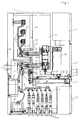
- a control panel which is particularly suitable for use in medium-voltage networks, has a cuboid frame (1) which has a door (2, 3) in the lower area and in the middle area on the front and a control box (4) in the upper area.
- a cable room (5) with cables (6) inserted from below, which are electrically connected via busbars (7) per phase to a current transformer (9) arranged on the rear (8) of the scaffold (1) and a voltage converter (10) arranged underneath .
- the current conductors 7 lead from the current transformers 9 to mating contacts 11 arranged above them, which are fixed via insulating sleeves 12 to an intermediate wall 13 connected to the frame 1.
- three counter contacts 11 are arranged side by side in the partition 13 in the horizontal direction.
- a switch compartment 15 Above the cable compartment 5 and between the middle door 3 and the partition 13 there is a switch compartment 15 in which a circuit breaker 16 in the form of a vacuum switch with a vertical axis is arranged for each phase.
- contact arms 17 are arranged at a distance above one another, which protrude into the depth of the scaffold and, in the illustrated retracted position of the circuit breaker 16, also have an electrical plug contact connection with lower mating contacts 11 fixed to the scaffold.
- the circuit breakers 16 are located on a drive box 18, from which an actuating rod 19 leads to the movable contact pin 20 of the circuit breaker and via which the respectively assigned circuit breaker 16 is switched on or off.
- the drive box 18 is mounted on a chassis 21, which is guided in wheels 23 which run parallel to one another from the area of the door 3 into the depth of the scaffold towards the partition 13.
- the running rails 23 sit on a base plate 24.1 of a tray cassette 24 designed for stability reasons, which, after inserting the switch carriage unit formed from the cassette 24, the chassis 21, the drive box 18 and the circuit breakers 16, is detachably attached to the scaffold by means of a horizontally extending cross member 25 1 is locked.
- the chassis 21 with the drive box 18 and the circuit breakers 16 in an extended position or disconnected position, in which the drive box facing the door 3 is approximated to the door 3 and the plug connections 11, 17 are adjusted by a corresponding distance to the door 3 Contact arms 17 are separated.
- a threaded spindle 26 is provided, which is rotatably mounted in the cross member 25 and is secured against axial adjustment and has a coupling piece (27) pointing towards the door 3 for attaching a hand crank.
- the at least at its inner end 26.1 additionally supported on the base plate 24.1 of the cassette 24 in a support bracket 28 threaded spindle 26 carries on its threaded portion a threaded nut piece 29 which by rotating the threaded spindle 26 from the position shown in FIG Insert the cassette and lock the crossbar in the scaffold 1 until it has moved adjacent to the support bracket 28.
- the chassis 21 with the circuit breaker 16 is in the extended position with separate contacts 11, 17, while it is in the position according to FIG. 1 with the threaded nut piece 29 approximated to the support tab 29 with mated contacts 11.17.
- a handlebar lever 30 is pivotally connected to the threaded nut piece 29, which is articulated at the other end at the toggle joint point 31 of a pair of toggle levers 32, which is pivotably attached to the base plate 24.1 on the one hand and to the chassis 21 on the other hand.
- Two such toggle lever transmissions 30, 31, 32 are preferably provided in a mirror image arrangement to the threaded spindle 26, the toggle levers of the toggle lever pairs 32 each being in the extended position in the retracted position of the shift carriage 21 and, in addition to an exact parallel guidance of the undercarriage 21, direct transmission from on the undercarriage 21 Particularly in the event of short-circuit currents, mechanical loads on the base plate 24.1 and thus relieve the threaded spindle 26.
- the shutter panels 34, 35 are adjustable in height parallel to the partition 13 on their two vertical side edges in vertical guide rails 36. The arrangement is such that in the retracted position of the chassis 21 (FIG. 1), with the contact arms 17 inserted into the openings 33, the upper shutter panel 34 is above the associated upper openings 33 and the lower shutter panel 35 is below the associated lower row of openings 33 .
- a gear arrangement which has a converts the central drive movement going in one direction into an opposite drive movement on the shutter diaphragms 34, 35.
- the horizontal rows of openings 33 can be arranged closely above one another in height because the shutter diaphragms 34 and 35 are moved away from one another into the position according to FIG. 1 during the opening movement into the release position.
- a translating lever mechanism is expediently used. Otherwise, a flexible push shaft in the manner of a Bowden cable can also be used.
- a translating lever gear is particularly suitable for a push rod arrangement which is displaceable relative to the partition and which is mounted transversely to the adjustment direction of the shutter plates 34, 35 and is located below the lower row of openings 33 in Such an arrangement can be such that the lower shutter diaphragm plunges into a gap between the partition 13 and the lever mechanism in the release position.
- the lever mechanism can also be arranged in close association with the lower openings 33, resulting in an overall compact construction in a small area.
- the push rod arrangement consists in particular of two mirror-image, parallel axially mounted partial push rods 37 which overlap with their longitudinal center end 38 and can be coupled together with an external drive in mutually rigid assignment.
- the push rod arrangement 37, 38 is coupled in the region of its opposite ends with a lever arm 39 each of two-armed levers 40, the pivot points 41 of which are stationary relative to the partition wall 13 and on the second lever arms 42 of which a support rod 43 is articulated, each of which is at the other end with one the shutter apertures 34, 35 are articulated.
- the pivots 41 of the two-armed lever 40 are located in a vertical projection laterally next to the outer openings 33, the first lever arm 39 being shorter than the second lever arm 42 and being guided with a sliding pin 44 in a slot guide 45 running perpendicular to the direction of adjustment of the partial push rods 37.
- the pivots 41 lie above the partial push rods 37.
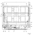
- the shutter covers 34, 35 are in the closed position and the push rod arrangement 37 is in an end position displaced laterally with respect to a central position, in the present case in the left end position.
- the two-armed lever 42 arranged there is in an approximately parallel position to the associated partial push rod 37, with its free end pointing towards the center.
- the support rod 43 connected to the second lever arm 42 is bent obliquely upwards from the center past the left lower opening 33 past a tab 46 and is thus connected in an articulated manner, which in turn is connected to the underside of the upper shutter panel 34 within the adjacent left guide rail 36 is.
- the other two-armed lever 40 is located on the other hand, in a pivoted position in which the second, longer lever arm 42 is pivoted upwards, in the present case beyond the vertical vertex, to the right guide rail located there. Accordingly, the free end 43.2 of the support rod 43 articulated thereon is at a height which lies above the free end of the other support rod 43.
- the upper end 43.2 of the right support rod 43 is connected to the lower shutter cover 35 via a downward-directed tab arranged in the right guide rail 36.
- the push rod arrangement 37, 38 is displaced in the opposite direction, according to FIG. 2, to the right by means of the drive described in more detail below.
- the two-armed levers 40 are pivoted counterclockwise via the sliding joints 44, 45, and because of the mirror-symmetrical design and mounting of the partial push rods 37, the levers 40 and the support rods 43 in the middle position, a mirror-image position of these parts with the same inclination of the levers 40 and same height of the ends 43.1 and 43.2 of the push rods 43 is reached.
- the right lever pivots further counterclockwise until the right longer lever arm 42 is at least approximately horizontal and the left lever arm 42 is adjusted to the left beyond the upper vertical central position, which Lever 40 thus have the opposite position compared to the arrangement of Figure 2. Accordingly, the associated support rods 43 are then adjusted in the opposite position, so that the free end 43.1 which has migrated upward and the associated upper shutter diaphragm 34 move upwards and the free end 43.2 of the other support rod 43 which has migrated downwards the lower shutter diaphragm 35 coupled therewith downwards and has placed in partial overlap with the lever 40 or the push rod arrangement 37.
- the outer drive arrangement for the transmission arrangement described above is arranged in the cassette 24 and has a slide plate 47 which is displaceably mounted parallel to the push rod arrangement 37, 38 and which, with a plug-in coupling part 48, engages with the overlapping end pieces 38 of the partial push rods 37 when the cassette 24 is inserted into the scaffold provided with the partition 13.
- the shutter plate 47 is in an outer (left) starting position with respect to the longitudinal axis of the threaded spindle 26, in which the threaded nut piece 29 is located close to the cross member 25 and the chassis 21 is accordingly in the extended position.
- the contact arms 17 of the switches 16 are located away from the openings 33 or at a distance from the associated shutter apertures 34, 35.
- a bevel pinion 48 is drive-connected, which meshes with a bevel gear 49, which on a perpendicular to the base plate 24.1.
- standing axis 49.1 is rotatably supported and carries a radially projecting eccentric pin 50 which is directed parallel to axis 49.1 and to base plate 24.1.
- the axis 49.1 is vertically adjusted at a distance from the threaded spindle 26 next to the slide plate 47.
- the slide plate 47 runs parallel to the plane of the running rails 23 and adjacent to the push rod arrangement 37 or the partition 13.
- the slide plate 47 is provided with a forward feed flank 51 which is perpendicular to its direction of adjustment, that is to say parallel to the longitudinal axis of the threaded spindle 26 and which in the effective range of the eccentric pin 50 at the beginning and during the course of the first rotation of the threaded spindle 26 during the adjustment of the chassis from the extended position Retracted position.
- the starting position is shown in FIG. If the threaded spindle 26 is rotated clockwise starting from this, the eccentric pin also moves clockwise and presses the slide plate 47 (always with respect to the longitudinal axis of the threaded spindle 26) to the right (downward in FIG. 3) via the forward transport flank 51, the right one End 47.1 in the other, with thin lines shown position moved to the right.
- the eccentric pin 50 is then adjusted from the initial position marked 0 after one revolution of the threaded spindle 26 to the rotational position marked 1, in which it then leaves the correspondingly shifted forward feed flank 51.
- the slide plate 47 is held in the respective end positions by means of a toggle spring arrangement 52. With the further revolutions of the eccentric pin 50 carried out in the same direction of rotation, there is no renewed or additional adjustment action on the slide plate 47.
- the gear arrangement coupled to the shutter diaphragms 34, 35 consequently remains in the release position then reached.
- a control lever 51.1 pivotally mounted in the area of the left end 47.2 is provided on the slide plate , which has a return transport flank 53 directed parallel to the forward transport flank 51, which is at such a distance from the forward transport flank 51 that the eccentric pin 50 can plunge unhindered into the gap 54 formed therebetween.
- control lever 51.1 is provided with a control flank 55 which is bent upwards perpendicular to the plane of the slide plate 47 and one in the direction of displacement of the slide plate 47 Inclination that corresponds to the slope of the threaded spindle 26 over its displacement.
- a control rod 56.1 is in sliding engagement with the control flank 55 and is slidably mounted parallel to the threaded spindle 26 and thus perpendicular to the displacement path of the slide plate 47.
- a spring 57.1 acts on the control rod, the force component of which loads the control rod 56.1 towards the control lever 51.1. In order to hold the control rod in the starting position shown in FIG.
- the control rod 56.1 is provided with an adjustable stop 56 which interacts with a counter-stop 57 formed on the handlebar lever 30. The stop 56 is adjusted so that the return flank 53 is parallel to the forward flank 51 in the position shown.
Landscapes
- Engineering & Computer Science (AREA)
- Power Engineering (AREA)
- Operating, Guiding And Securing Of Roll- Type Closing Members (AREA)
- Patch Boards (AREA)
- Trip Switchboards (AREA)
Applications Claiming Priority (2)
| Application Number | Priority Date | Filing Date | Title |
|---|---|---|---|
| DE19615297 | 1996-04-18 | ||
| DE19615297A DE19615297A1 (de) | 1996-04-18 | 1996-04-18 | Schaltfeld mit Shutterblenden |
Publications (3)
| Publication Number | Publication Date |
|---|---|
| EP0802596A2 true EP0802596A2 (fr) | 1997-10-22 |
| EP0802596A3 EP0802596A3 (fr) | 1998-08-19 |
| EP0802596B1 EP0802596B1 (fr) | 2003-07-09 |
Family
ID=7791622
Family Applications (1)
| Application Number | Title | Priority Date | Filing Date |
|---|---|---|---|
| EP97106218A Expired - Lifetime EP0802596B1 (fr) | 1996-04-18 | 1997-04-16 | Tableau de distribution avec obturateur panneau |
Country Status (3)
| Country | Link |
|---|---|
| EP (1) | EP0802596B1 (fr) |
| DE (2) | DE19615297A1 (fr) |
| ES (1) | ES2197262T3 (fr) |
Cited By (2)
| Publication number | Priority date | Publication date | Assignee | Title |
|---|---|---|---|---|
| CN117712889A (zh) * | 2023-12-15 | 2024-03-15 | 山东厚俞实业有限公司 | 一种自动通风的电力预制舱 |
| CN121216247A (zh) * | 2025-10-10 | 2025-12-26 | 杭州华宏通信设备有限公司 | 一种具有散热结构的防火型计量箱 |
Families Citing this family (2)
| Publication number | Priority date | Publication date | Assignee | Title |
|---|---|---|---|---|
| DE102006050477B4 (de) * | 2005-10-21 | 2008-02-28 | Abb Technology Ag | Mittelspannungsschaltanlage mit Eingießpolteilen und Einfahrkontaktanordnungen |
| DE102011000837A1 (de) * | 2011-02-21 | 2012-08-23 | Ids-Technology Gmbh | Schaltvorrichtung für Schaltschränke |
Family Cites Families (8)
| Publication number | Priority date | Publication date | Assignee | Title |
|---|---|---|---|---|
| GB807952A (en) * | 1955-05-13 | 1959-01-28 | English Electric Co Ltd | Improvements in and relating to withdrawable electric switchgear |
| GB881705A (en) * | 1958-11-26 | 1961-11-08 | Allis Chalmers Mfg Co | Improved enclosed electrical switchboard structure |
| DE2805617A1 (de) * | 1978-02-10 | 1979-08-16 | Sachsenwerk Licht & Kraft Ag | Lichtbogenfeste hochspannungsschaltzelle |
| AT355127B (de) * | 1978-04-17 | 1980-02-11 | Sprecher & Schuh Ag | Geschottete schaltzelle |
| US4285026A (en) * | 1979-08-13 | 1981-08-18 | Gould Inc. | Parallel plane shutter for LK breaker |
| EP0099096A1 (fr) * | 1982-07-14 | 1984-01-25 | Hoechst Aktiengesellschaft | Procédé de séparation d'ions de métaux lourds à partir de phosphate brut |
| DE8512452U1 (de) * | 1985-04-26 | 1985-06-20 | Concordia Sprecher-Schaltgeräte GmbH, 7024 Filderstadt | Steuerbare Verschlußvorrichtung |
| DE3812853C1 (fr) * | 1988-04-18 | 1989-11-09 | Sachsenwerk Ag, 8400 Regensburg, De |
-
1996
- 1996-04-18 DE DE19615297A patent/DE19615297A1/de not_active Withdrawn
-
1997
- 1997-04-16 EP EP97106218A patent/EP0802596B1/fr not_active Expired - Lifetime
- 1997-04-16 ES ES97106218T patent/ES2197262T3/es not_active Expired - Lifetime
- 1997-04-16 DE DE59710393T patent/DE59710393D1/de not_active Expired - Lifetime
Cited By (2)
| Publication number | Priority date | Publication date | Assignee | Title |
|---|---|---|---|---|
| CN117712889A (zh) * | 2023-12-15 | 2024-03-15 | 山东厚俞实业有限公司 | 一种自动通风的电力预制舱 |
| CN121216247A (zh) * | 2025-10-10 | 2025-12-26 | 杭州华宏通信设备有限公司 | 一种具有散热结构的防火型计量箱 |
Also Published As
| Publication number | Publication date |
|---|---|
| ES2197262T3 (es) | 2004-01-01 |
| DE59710393D1 (de) | 2003-08-14 |
| DE19615297A1 (de) | 1997-10-23 |
| EP0802596B1 (fr) | 2003-07-09 |
| EP0802596A3 (fr) | 1998-08-19 |
Similar Documents
| Publication | Publication Date | Title |
|---|---|---|
| DE3542979C2 (de) | Geschotteter Schaltschrank | |
| EP0227586B1 (fr) | Installation de commutation électrique avec un compartiment-tiroir pouvant contenir un dispositif de commutation | |
| EP0115739B1 (fr) | Interrupteur à vide à deux tubes interrupteurs en série par pôle | |
| EP0564057B1 (fr) | Appareillage de commutation à gaz isolant avec un interrupteur à vide | |
| DE69209443T2 (de) | Schaltfeld | |
| EP0803140B1 (fr) | Cadre de rack a systeme de contacts de coupure | |
| EP0013358B1 (fr) | Disjoncteur de puissance ou de charge, en particulier pour réseaux de moyenne tension | |
| EP0802596B1 (fr) | Tableau de distribution avec obturateur panneau | |
| EP0802595B1 (fr) | Tableau de distribution avec un chassis | |
| EP0338328B1 (fr) | Armoire de commutation compartimentée | |
| DE2949774C3 (de) | Betätigungs- und Verriegelungsvorrichtung für eine Schaltanlage | |
| EP1087483A1 (fr) | Installation de commutation électrique | |
| DE2931459C2 (de) | Trennschalter | |
| DE10260371A1 (de) | Niederspannungs-Leistungsschalter | |
| DE9000374U1 (de) | Gekapselte, trennerlose Schaltanlage | |
| DE3117495C2 (de) | Einfahranordnung | |
| DE2948130C2 (de) | Schalter mit Erdungsvorrichtung | |
| EP2146361B1 (fr) | Dispositif de commutation pour un interrupteur électrique, notamment un interrupteur à moyenne tension | |
| DE10010738B4 (de) | Schaltfeld mit einem Fahrgestell | |
| DE3136771A1 (de) | Sprungfederantrieb fuer das bewegliche schaltstueck eines elektrischen erdungs- oder trennschalters | |
| CH625915A5 (en) | Electrical high-voltage switching installation having a disconnector truck | |
| DE2312900A1 (de) | Trennschalter fuer elektrische leitungen und damit verbindbarer lastschalter | |
| DE19613151C2 (de) | Elektrisches Schaltfeld | |
| AT200216B (de) | Gekapseltes Hochspannungs-Schaltfeld mit Doppelsammelschienen | |
| EP2237303B1 (fr) | Unité de fusible pour un panneau d'interrupteurs d'une installation de commutation électrique, notamment d'une installation de commutation de moyenne tension à air isolé |
Legal Events
| Date | Code | Title | Description |
|---|---|---|---|
| PUAI | Public reference made under article 153(3) epc to a published international application that has entered the european phase |
Free format text: ORIGINAL CODE: 0009012 |
|
| AK | Designated contracting states |
Kind code of ref document: A2 Designated state(s): DE ES FR GB IT NL |
|
| 17P | Request for examination filed |
Effective date: 19971118 |
|
| PUAL | Search report despatched |
Free format text: ORIGINAL CODE: 0009013 |
|
| AK | Designated contracting states |
Kind code of ref document: A3 Designated state(s): DE ES FR GB IT NL |
|
| 17Q | First examination report despatched |
Effective date: 20020513 |
|
| GRAH | Despatch of communication of intention to grant a patent |
Free format text: ORIGINAL CODE: EPIDOS IGRA |
|
| GRAH | Despatch of communication of intention to grant a patent |
Free format text: ORIGINAL CODE: EPIDOS IGRA |
|
| GRAA | (expected) grant |
Free format text: ORIGINAL CODE: 0009210 |
|
| AK | Designated contracting states |
Designated state(s): DE ES FR GB IT NL |
|
| REG | Reference to a national code |
Ref country code: GB Ref legal event code: FG4D Free format text: NOT ENGLISH |
|
| GBT | Gb: translation of ep patent filed (gb section 77(6)(a)/1977) | ||
| REF | Corresponds to: |
Ref document number: 59710393 Country of ref document: DE Date of ref document: 20030814 Kind code of ref document: P |
|
| REG | Reference to a national code |
Ref country code: ES Ref legal event code: FG2A Ref document number: 2197262 Country of ref document: ES Kind code of ref document: T3 |
|
| ET | Fr: translation filed | ||
| PLBE | No opposition filed within time limit |
Free format text: ORIGINAL CODE: 0009261 |
|
| STAA | Information on the status of an ep patent application or granted ep patent |
Free format text: STATUS: NO OPPOSITION FILED WITHIN TIME LIMIT |
|
| 26N | No opposition filed |
Effective date: 20040414 |
|
| NLT1 | Nl: modifications of names registered in virtue of documents presented to the patent office pursuant to art. 16 a, paragraph 1 |
Owner name: ALSTOM SACHSENWERK GMBH |
|
| REG | Reference to a national code |
Ref country code: FR Ref legal event code: CD |
|
| NLT1 | Nl: modifications of names registered in virtue of documents presented to the patent office pursuant to art. 16 a, paragraph 1 |
Owner name: AREVA SACHSENWERK GMBH |
|
| REG | Reference to a national code |
Ref country code: FR Ref legal event code: CD |
|
| PGFP | Annual fee paid to national office [announced via postgrant information from national office to epo] |
Ref country code: GB Payment date: 20100318 Year of fee payment: 14 |
|
| PGFP | Annual fee paid to national office [announced via postgrant information from national office to epo] |
Ref country code: NL Payment date: 20100421 Year of fee payment: 14 Ref country code: IT Payment date: 20100427 Year of fee payment: 14 |
|
| REG | Reference to a national code |
Ref country code: DE Ref legal event code: R084 Ref document number: 59710393 Country of ref document: DE |
|
| PGFP | Annual fee paid to national office [announced via postgrant information from national office to epo] |
Ref country code: ES Payment date: 20110419 Year of fee payment: 15 Ref country code: FR Payment date: 20110427 Year of fee payment: 15 |
|
| REG | Reference to a national code |
Ref country code: NL Ref legal event code: V1 Effective date: 20111101 |
|
| GBPC | Gb: european patent ceased through non-payment of renewal fee |
Effective date: 20110416 |
|
| PG25 | Lapsed in a contracting state [announced via postgrant information from national office to epo] |
Ref country code: NL Free format text: LAPSE BECAUSE OF NON-PAYMENT OF DUE FEES Effective date: 20111101 |
|
| PG25 | Lapsed in a contracting state [announced via postgrant information from national office to epo] |
Ref country code: GB Free format text: LAPSE BECAUSE OF NON-PAYMENT OF DUE FEES Effective date: 20110416 Ref country code: IT Free format text: LAPSE BECAUSE OF NON-PAYMENT OF DUE FEES Effective date: 20110416 |
|
| PGFP | Annual fee paid to national office [announced via postgrant information from national office to epo] |
Ref country code: DE Payment date: 20120621 Year of fee payment: 16 |
|
| REG | Reference to a national code |
Ref country code: FR Ref legal event code: ST Effective date: 20121228 |
|
| PG25 | Lapsed in a contracting state [announced via postgrant information from national office to epo] |
Ref country code: FR Free format text: LAPSE BECAUSE OF NON-PAYMENT OF DUE FEES Effective date: 20120430 |
|
| REG | Reference to a national code |
Ref country code: ES Ref legal event code: FD2A Effective date: 20130716 |
|
| PG25 | Lapsed in a contracting state [announced via postgrant information from national office to epo] |
Ref country code: ES Free format text: LAPSE BECAUSE OF NON-PAYMENT OF DUE FEES Effective date: 20120417 |
|
| PG25 | Lapsed in a contracting state [announced via postgrant information from national office to epo] |
Ref country code: DE Free format text: LAPSE BECAUSE OF NON-PAYMENT OF DUE FEES Effective date: 20131101 |
|
| REG | Reference to a national code |
Ref country code: DE Ref legal event code: R119 Ref document number: 59710393 Country of ref document: DE Effective date: 20131101 |