EP0803317B1 - Machine outil - Google Patents
Machine outil Download PDFInfo
- Publication number
- EP0803317B1 EP0803317B1 EP97102969A EP97102969A EP0803317B1 EP 0803317 B1 EP0803317 B1 EP 0803317B1 EP 97102969 A EP97102969 A EP 97102969A EP 97102969 A EP97102969 A EP 97102969A EP 0803317 B1 EP0803317 B1 EP 0803317B1
- Authority
- EP
- European Patent Office
- Prior art keywords
- machine tool
- carriage
- box
- roller
- working space
- Prior art date
- Legal status (The legal status is an assumption and is not a legal conclusion. Google has not performed a legal analysis and makes no representation as to the accuracy of the status listed.)
- Expired - Lifetime
Links
Images


Classifications
-
- B—PERFORMING OPERATIONS; TRANSPORTING
- B23—MACHINE TOOLS; METAL-WORKING NOT OTHERWISE PROVIDED FOR
- B23Q—DETAILS, COMPONENTS, OR ACCESSORIES FOR MACHINE TOOLS, e.g. ARRANGEMENTS FOR COPYING OR CONTROLLING; MACHINE TOOLS IN GENERAL CHARACTERISED BY THE CONSTRUCTION OF PARTICULAR DETAILS OR COMPONENTS; COMBINATIONS OR ASSOCIATIONS OF METAL-WORKING MACHINES, NOT DIRECTED TO A PARTICULAR RESULT
- B23Q11/00—Accessories fitted to machine tools for keeping tools or parts of the machine in good working condition or for cooling work; Safety devices specially combined with or arranged in, or specially adapted for use in connection with, machine tools
- B23Q11/08—Protective coverings for parts of machine tools; Splash guards
- B23Q11/085—Flexible coverings, e.g. coiled-up belts
-
- B—PERFORMING OPERATIONS; TRANSPORTING
- B23—MACHINE TOOLS; METAL-WORKING NOT OTHERWISE PROVIDED FOR
- B23Q—DETAILS, COMPONENTS, OR ACCESSORIES FOR MACHINE TOOLS, e.g. ARRANGEMENTS FOR COPYING OR CONTROLLING; MACHINE TOOLS IN GENERAL CHARACTERISED BY THE CONSTRUCTION OF PARTICULAR DETAILS OR COMPONENTS; COMBINATIONS OR ASSOCIATIONS OF METAL-WORKING MACHINES, NOT DIRECTED TO A PARTICULAR RESULT
- B23Q1/00—Members which are comprised in the general build-up of a form of machine, particularly relatively large fixed members
- B23Q1/25—Movable or adjustable work or tool supports
- B23Q1/44—Movable or adjustable work or tool supports using particular mechanisms
- B23Q1/56—Movable or adjustable work or tool supports using particular mechanisms with sliding pairs only, the sliding pairs being the first two elements of the mechanism
- B23Q1/60—Movable or adjustable work or tool supports using particular mechanisms with sliding pairs only, the sliding pairs being the first two elements of the mechanism two sliding pairs only, the sliding pairs being the first two elements of the mechanism
- B23Q1/62—Movable or adjustable work or tool supports using particular mechanisms with sliding pairs only, the sliding pairs being the first two elements of the mechanism two sliding pairs only, the sliding pairs being the first two elements of the mechanism with perpendicular axes, e.g. cross-slides
- B23Q1/621—Movable or adjustable work or tool supports using particular mechanisms with sliding pairs only, the sliding pairs being the first two elements of the mechanism two sliding pairs only, the sliding pairs being the first two elements of the mechanism with perpendicular axes, e.g. cross-slides a single sliding pair followed perpendicularly by a single sliding pair
- B23Q1/626—Movable or adjustable work or tool supports using particular mechanisms with sliding pairs only, the sliding pairs being the first two elements of the mechanism two sliding pairs only, the sliding pairs being the first two elements of the mechanism with perpendicular axes, e.g. cross-slides a single sliding pair followed perpendicularly by a single sliding pair followed perpendicularly by a single sliding pair
-
- Y—GENERAL TAGGING OF NEW TECHNOLOGICAL DEVELOPMENTS; GENERAL TAGGING OF CROSS-SECTIONAL TECHNOLOGIES SPANNING OVER SEVERAL SECTIONS OF THE IPC; TECHNICAL SUBJECTS COVERED BY FORMER USPC CROSS-REFERENCE ART COLLECTIONS [XRACs] AND DIGESTS
- Y10—TECHNICAL SUBJECTS COVERED BY FORMER USPC
- Y10T—TECHNICAL SUBJECTS COVERED BY FORMER US CLASSIFICATION
- Y10T409/00—Gear cutting, milling, or planing
- Y10T409/30—Milling
- Y10T409/30392—Milling with means to protect operative or machine [e.g., guard, safety device, etc.]
-
- Y—GENERAL TAGGING OF NEW TECHNOLOGICAL DEVELOPMENTS; GENERAL TAGGING OF CROSS-SECTIONAL TECHNOLOGIES SPANNING OVER SEVERAL SECTIONS OF THE IPC; TECHNICAL SUBJECTS COVERED BY FORMER USPC CROSS-REFERENCE ART COLLECTIONS [XRACs] AND DIGESTS
- Y10—TECHNICAL SUBJECTS COVERED BY FORMER USPC
- Y10T—TECHNICAL SUBJECTS COVERED BY FORMER US CLASSIFICATION
- Y10T409/00—Gear cutting, milling, or planing
- Y10T409/30—Milling
- Y10T409/306664—Milling including means to infeed rotary cutter toward work
- Y10T409/307728—Milling including means to infeed rotary cutter toward work including gantry-type cutter-carrier
-
- Y—GENERAL TAGGING OF NEW TECHNOLOGICAL DEVELOPMENTS; GENERAL TAGGING OF CROSS-SECTIONAL TECHNOLOGIES SPANNING OVER SEVERAL SECTIONS OF THE IPC; TECHNICAL SUBJECTS COVERED BY FORMER USPC CROSS-REFERENCE ART COLLECTIONS [XRACs] AND DIGESTS
- Y10—TECHNICAL SUBJECTS COVERED BY FORMER USPC
- Y10T—TECHNICAL SUBJECTS COVERED BY FORMER US CLASSIFICATION
- Y10T409/00—Gear cutting, milling, or planing
- Y10T409/30—Milling
- Y10T409/309576—Machine frame
Definitions
- the present invention relates to a machine tool a clamping surface for workpieces to be machined having workpiece table, one in a work area above of the workpiece table relative to this via a sliding mechanism movable spindle head with a tool for Machining the workpiece-receiving spindle, and three slides movable orthogonally to each other in the slide mechanism, of which the second carriage can be moved on the first and the third carriage can be moved on the second carriage is mounted, the spindle head with the third slide connected and the first slide above the clamping surface is arranged.
- the spindle head is in three mutually orthogonal coordinate directions, namely the x-, the y- and the z-direction in a work area Movable above the workpiece table.
- the shift mechanism provided for this purpose is the first Slide an x-slide in the area of the clamping surface the workpiece table, preferably below the clamping surface, is arranged. On this x-slide is the second slide the y-slide arranged, which can be moved transversely to the x-slide is so that the x and y slides are one plane clamp that is parallel to the clamping surface.
- a stand is arranged on the y-slide, which holds the entire The height of the working area is covered and at its upper end carries the third slide, namely the z-slide, on the the spindle head is attached, which thus from above into the Immersed workspace.
- the stand runs on the rear wall of the Working space.
- the stand Depending on the height of the work area, the stand has a relative large mass, so that when moving the spindle head in x or y-direction of the achievable maximum kinematic acceleration There are limits. Accelerating and braking the Stands can not be realized in any short period of time become.
- the known machine tool also has a panel that covers the machine tool on the outside and on the other hand provides for a lining of the work area in order to the sliding mechanism in front of chips as well as drilling and cooling oil protect.
- the slide and guide rails as well as the stand are protected by telescopic covers, so to speak variable-length covers form, so that the of the Sliding mechanism protruding parts of the Machine tool not through slots in the panel have to go through the chips and cooling and drilling water could get into the sliding mechanism.
- the telescopic covers include stackable, U-shaped ones Sheet metal parts, e.g. arranged on both sides of the x-slide and overlap the guides for this sled and thus protect against contamination.
- the large mass of the telescopic covers is Disadvantage that is not only constructive but also because of the large surfaces to be sealed is conditional, so that the telescopic covers on the acceleration problems mentioned above contribute.
- Another disadvantage is that the sheet metal parts in particular at high travel speeds when pushing together as well as beating apart. These blows are not just a nuisance, they affect because of the associated vibrations, the machining accuracy the well-known machine tool.
- a machine tool is known from EP 0 194 173 A2 mentioned at the beginning known, also three orthogonal to each other movable carriage are provided.
- the first sledge extends across the entire work area and is located above the clamping surface.
- On the first Slide is a second slide that can be moved perpendicular to it provided that thus move above the work area leaves.
- On this second carriage is the spindle head carrying third sled arranged.
- DE 29 46 825 describes a roller blind-like design Cover for protecting guideways on a machine tool.
- the roller blind cover is at one end movable carriage and other end on a drum attached to which they are pre-stressed by a torsion spring is wound up.
- roller blind covers are said to have the disadvantage of being relatively short Have lifespan, because when moving the sled constantly results in a change in the tension of the cover.
- This publication proposes to solve the problem, the winding shaft in the drum with the drive of the slide, so that when moving the carriage by rotating the shaft the bias of the torsion spring is adjusted.
- this task solved in that the first carriage behind the work space and a blind cover on both sides of the first slide is arranged, which is in the process of the first Slides up and down and with its roller blind surface Covers the work area.
- the inventors of the present application have recognized that in that the x-slide and thus also the y-slide be put up, an overall compact arrangement can be achieved in which the stand have only a small height got to. However, with the lower height of the stand also a much lower mass, so that with the new Machine tool greater accelerations are possible.
- blind cover it is an advantage that at very simple construction with a variable length cover very light weight is used, which increases the moving mass further reduced, which is beneficial to the Acceleration behavior of the spindle head affects.
- Known machine tools had to be variable in length Covers are arranged in the area of the clamping surface, in other words, precisely where the workpieces are machined and thus a large number of chips arise, some of which with great speed and force from the workpiece or be flung away from the tool. To these burdens to withstand, the known covers had to be very mechanical be stable.
- the first Sledge is arranged above the work area.
- both Sides of the first carriage one each to the top of the Working area reaching cheek is arranged on each attached the associated blind cover with its free end is, the roller blind cover each on one roller arranged on an outer side of the work space winds.
- This measure has the advantage that the role itself can be stationary, so that only the roller blind itself is proceeded. This helps ensure that the process of the spindle head to be moved mass is reduced again.
- the spindle head is from one to the other second carriage attached box is surrounded, from which the Spindle head is at least partially extendable down, and between the cheeks in the direction of the movement of the second Is slidable in the work area.
- first Sledges are two e.g. vertical cheeks arranged between which the box runs back and forth in the y direction. both sides the cheeks that run in the x-direction with the x-slide, the two blind covers are provided, which are in the Movement of the carriage in the x direction accordingly transact. Remain in the y direction when moving the spindle head the blind covers, however, are unaffected, the box runs rather between the two cheeks.
- cheeks as well as the blind surfaces run diagonally upwards and forwards, so that the blind covers cover the work area diagonally upwards and backwards.
- a roll of another blind cover is arranged, which is guided with its free end on the box and with its roller blind surface for sealing the work area above the box.
- roller blind cover is attached to a wiper rail that height-adjustable on the box and on the cheeks is slidably guided in the longitudinal direction.
- the advantage here is that the inclination of the blind surface Upper blind cover not changed when the box is in the y direction is proceeded. If the box is e.g. between the cheeks moved forward, the scraper rail moves up the box as it follows the course of the cheeks must follow diagonally above. When the box is moved back, the Scraper rail thanks to the simultaneous guidance on the cheeks as well as pulled down on the box, taking the Strips the front of the box and thus from adhering Cleans chips.
- Another advantage of this arrangement is that the upper one The blind cover can cover the cheeks on the side, however on them and thus for an even better coverage of the Working space in this area.
- scraper rail on two Sliding blocks are attached, each in a vertical Groove are stored on the box and an oblique slot have, in each of which engages a scraper rail, which is preferably laterally adjustable on the respective cheek is attached.
- the advantage here is that the positive guidance of the scraper rail the top roller blind cover in a structurally very simple manner is realized.
- the sliding block is on the one hand in the vertical Groove guided on the box and slides on the other hand the inclined scraper rail.
- Another advantage with this construction is that the groove itself, so to speak cleans itself of shavings etc., as these when the Box between the cheeks of those descending Sliding blocks can be pushed out.
- blind covers are under Wind the spring tension on the respective roll or the rolls are drivingly connected to the assigned slide.
- the known winding of the blind covers under Spring tension has the advantage that this construction is very is simply constructed, while the active "drive” of the blind covers e.g. via a belt-like coupling with the assigned one Carriage for a reliable winding and unwinding of the Blinds covers ensures.
- this measure is also constructively advantageous because it is allows easy protection of the spindle as well as the latter surrounding tool changer from contamination, this Pipe has a very low weight, so this measure overall also to a reduction in mass and thus to one Contributes to increasing the travel speed.
- a lower cover plate of the box is provided, which is located between the cheeks to the rear extends the first sled.
- a covering which is the work space opposite the machine tool as well seals to the outside and at least one side service door has that is accessible from outside the work area.
- machine tool over Rolling is movable in the operation of the machine tool are disabled and if the machine tool is on adjustable stand stands.
- rollers are extended or the stands are retracted.
- the new machine tool with the x-slide raised as well as the light roller blind covers is particularly of Advantage that only small masses when moving the spindle head must be moved so that very high for the spindle head Allow travel speeds and accelerations to be achieved.
- this new machine concept has another one Advantage that the work space is significantly more effective and makes sealing easier. This is mainly due to the fact that in lower area of the work area where the heaviest pollution and the greatest mechanical stress on the cladding occurs, fixed cover elements can be used while the Length-adjustable covers only in the upper area of the Work space are required where the requirements for the Resilience and tightness of the covers, however, clearly is less.
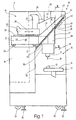
- 10 denotes a machine tool, the one Fairing 11 has.
- the machine tool 10 is used for Machining workpieces 12 on a workpiece table 13, which has a clamping surface 14 for this purpose, be spanned.
- the workpieces 12 are machined in a work space 15, in which a spindle head 16 in three coordinate directions is movable.
- the spindle head 16 has a spindle 17, which carries a schematically indicated tool 18 with which the workpiece 12 is processed.
- a displacement mechanism is used to move the spindle head 16 19 provided completely outside of the work space 15 is arranged.
- the displacement mechanism 19 comprises a first carriage 21, in the direction of an x coordinate indicated at 22
- Guides 23 is slidable behind the work space 15 and are arranged clearly above the clamping surface 14.
- the guides 23 are so far above the usual work space 15 that the spindle 17 with the tool 18 so to speak works in front of and below the first carriage 21.
- the y coordinate can be moved transversely to the x coordinate 22.
- a stand 27 is arranged on the second slide 25, on which a third carriage 28 in the direction of one at 29 indicated z coordinate is displaceable.
- the third The spindle head 16 is attached to the carriage 28.
- the spindle head 16 can consequently be moved via the displacement mechanism 19 in the three mutually orthogonal coordinates x, y and z im Working space 15 can be moved.
- FIG. 1 31 The position of a service door is also shown schematically in FIG. 1 31 indicated in the panel 11, about the operating personnel from the side on the sliding mechanism 19 and others Components of the machine tool 10 can access.
- Machine tool 10 in a production line side by side arranged with other machine tools and still problem-free can be maintained, it has rollers 32, 33, over which it is movable.
- rollers 32, 33 there are stands 34, 35 arranged in the state shown in Fig. 1 down protrude over the rollers 32, 33 so that the machine tool 10 is fixed and can be aligned with regard to their location.
- the Stand 34, 35 retracted or the rollers 32, 33 extended.
- the work area 15 is in its lower area by one 36 only indicated solid cladding surrounding the Fully surrounds work space 15 in the lower area and prevents 12 generated during machining of the workpieces Chips from the work area 15 into the area of the machines mechanics arrive.
- the cheek 37 is a sheet metal side part that is in Fig. 1 starting from the carriage 21 obliquely to the right extends above.
- a lateral roller blind cover 39 is provided on the cheek 37, of which in Fig. 1 only the fastening area on the cheek 37 can be seen. There is a corresponding one on the other cheek Blind cover provided, which can be seen in Fig. 2.
- blind cover 42 There is an upper one between the side blind covers Blind cover 42 is provided, which at the upper end 43 of the Cheek 37 has a roller 44.
- the upper blind cover 42 is with its lower free end 45 on a wiper rail 46 attached via a vertical groove 47 in still too descriptively mounted on the box 38.
- the scraper rail 46 is also mounted on the cheek 37, so that when moving the box 38 against the Cheek 37 on the one hand on box 38 up or down as well on the other hand, moved along the cheek 37.
- the top blind cover 42 is extended or retracted along an arrow 49, but their tendency does not change.
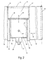
- Fig. 2 is a plan view in Fig. 1 from the right to the Working space 15 of the machine tool 10 the arrangement of the easier to recognize individual blind covers.
- Fig. 2 it can first be seen that on the right side of the Box 38 another cheek 51 is arranged on the one further roller blind cover 52 is attached, which on a at 53 indicated roll can be wound up or unwound from this is.
- Fig. 2 also shows that the roller 44 of the upper blind cover 42 between the two upper ends 43, 43 'of the cheeks 37 and 51 is rotatably mounted.
- the width of the shade cover 42 is chosen so that they not only the box 38 but also still at least partially covers the cheeks 37, 51 with to which it also applies.
- Fig. 3 is a sectional view along the line III-III 1 that the cheek 37 in cross section L-shaped and the wiper rail on its short arm 58 55 carries, which is fastened via a screw 59 and is adjustable in terms of its distance from the box 38.
- a sliding block 61 is supported, in which an oblique slot 62 is provided, the upper opening 63 and lower opening 64 are indicated in Fig. 3.
- this oblique slot 62 runs the free outer end of the scraper rail 55th
- box 38 Similar arrangement with a comparable, but mirror image trained sliding block provided.
- the sliding blocks 61 made of plastic are preferably made of polyamide.
Landscapes
- Engineering & Computer Science (AREA)
- Mechanical Engineering (AREA)
- Auxiliary Devices For Machine Tools (AREA)
- Machine Tool Units (AREA)
- Automatic Tool Replacement In Machine Tools (AREA)
Claims (16)
- Machine-outil comportant une table porte-pièce (13) qui présente une surface de bridage (14) pour des pièces (12) à usiner, une tête de broche (16) qui est déplaçable dans un espace de travail (15) au-dessus de la table porte-pièce (13), par rapport à celle-ci, au moyen d'un mécanisme de coulissement (19) et qui comporte une broche (17) recevant des outils (18) pour l'usinage des pièces (12), ainsi que trois chariots (21, 25, 28) déplaçables orthogonalement l'un par rapport à l'autre dans le mécanisme de coulissement (19), dont le deuxième chariot (25) est monté déplaçable sur le premier chariot (21), et le troisième chariot (28) est monté déplaçable sur le deuxième chariot (25), la tête de broche (16) étant reliée au troisième chariot (28) et le premier chariot (21) étant disposé au-dessus de la surface de bridage (14),
caractérisée en ce que le premier chariot (21) est disposé derrière l'espace de travail (15) et sur chacun des deux côtés du premier chariot (21) est disposé un capot à enroulement (39, 52) qui, pendant le déplacement du premier chariot (21), s'enroule, respectivement se déroule et recouvre l'espace de travail (15) par sa surface de capot à enroulement. - Machine-outil selon la revendication 1, caractérisée en ce que le premier chariot (21) est disposé au-dessus de l'espace de travail (15).
- Machine-outil selon la revendication 1 ou 2, caractérisée en ce que sur chacun des deux côtés du premier chariot (21) est disposée une joue (37, 51) qui s'étend jusqu'à l'extrémité supérieure de l'espace de travail (15) et à laquelle est fixé le capot à enroulement (39, 52) correspondant, par son extrémité libre, le capot à enroulement (39, 52) s'enroulant dans chaque cas sur un rouleau (53) disposé sur un côté extérieur de l'espace de travail (15).
- Machine-outil selon la revendication 3, caractérisée en ce que la tête de broche (16) est entourée par un caisson, fixé au deuxième chariot (25), duquel la tête de broche (16) peut être extraite au moins partiellement vers le bas, et qui est déplaçable entre les joues (37, 51) dans le sens du déplacement du deuxième chariot (25) dans l'espace de travail (15).
- Machine-outil selon la revendication 4, caractérisée en ce que les joues (37, 51) comportent chacune un racleur (55, 56) qui s'applique contre le caisson (38) déplaçable.
- Machine-outil selon l'une des revendications 3 à 5, caractérisée en ce que les joues (37, 51) ainsi que les surfaces de capot à enroulement s'étendent obliquement vers le haut et vers l'avant, ce qui fait que les capots à enroulement (39, 52) recouvrent obliquement vers le haut et vers l'arrière l'espace de travail (15).
- Machine-outil selon l'une des revendications 3 à 6, caractérisée en ce qu'entre les joues (37, 51), à leurs extrémités supérieures et avant (43, 43'), est disposé un rouleau (44) d'un autre capot à enroulement (42), lequel rouleau est guidé par son extrémité libre (45) sur le caisson (38) et assure, par sa surface de capot à enroulement, une étanchéité de l'espace de travail (15) au-dessus du caisson (38).
- Machine-outil selon la revendication 7, caractérisée en ce que l'extrémité libre (45) de l'autre capot à enroulement (42) est fixée à un rail de raclage (46) qui est monté de manière à pouvoir coulisser en hauteur sur le caisson (38), et qui est guidé coulissant sur les joues (37, 51), dans leur direction longitudinale.
- Machine-outil selon la revendication 8, caractérisée en ce que le rail de raclage (46) est fixé à deux coulisseaux (61) qui sont montés chacun dans une rainure verticale (47, 47') sur le caisson (38) et qui présentent une fente oblique (62), dans laquelle s'engage respectivement un rail de raclage (55, 56) qui est fixé à la joue (37, 51) respective, de préférence de manière déplaçable latéralement.
- Machine-outil selon l'une des revendications 1 à 9, caractérisée en ce que les capots à enroulement (39, 42, 52) s'enroulent sur le rouleau (44, 53) respectif, par tension d'un ressort.
- Machine-outil selon l'une des revendications 3 à 9, caractérisée en ce que les rouleaux (44, 53) sont reliés en entraínement au chariot (21, 25) associé.
- Machine-outil selon l'une des revendications 4 à 11, caractérisée en ce qu'au troisième chariot (38) est fixé un tube (50) qui entoure la tête de broche (16) et qui, pendant son déplacement, coulisse dans une ouverture inférieure du caisson (38), de dimensions adaptées.
- Machine-outil selon la revendication 12, caractérisée en ce qu'il est prévu une tôle de couverture inférieure (57) du caisson (38), qui s'étend entre les joues (37, 51) vers l'arrière, au-dessous du premier chariot (21).
- Machine-outil selon l'une des revendications 1 à 13, caractérisée en ce qu'il est prévu un revêtement (11, 36) qui rend étanche l'espace de travail (15) par rapport à la machine-outil ainsi que vers l'extérieur, et qui comporte au moins une porte de maintenance latérale (31) qui est accessible depuis l'extérieur de l'espace de travail (15).
- Machine-outil selon la revendication 14, caractérisée en ce qu'elle est déplaçable au moyen de rouleaux (32, 33) qui sont rendus inopérants pendant le fonctionnement de la machine-outil, et en ce que la machine-outil est placée sur des montants (34, 35) ajustables.
- Machine-outil selon la revendication 15, caractérisée en ce que pour le déplacement de la machine-outil (10), les rouleaux (32, 33) peuvent être sortis, respectivement les montants (34, 35) peuvent être rentrés.
Applications Claiming Priority (2)
| Application Number | Priority Date | Filing Date | Title |
|---|---|---|---|
| DE19616433A DE19616433C2 (de) | 1996-04-25 | 1996-04-25 | Werkzeugmaschine mit Arbeitsraumabdeckung |
| DE19616433 | 1996-04-25 |
Publications (2)
| Publication Number | Publication Date |
|---|---|
| EP0803317A1 EP0803317A1 (fr) | 1997-10-29 |
| EP0803317B1 true EP0803317B1 (fr) | 2002-01-30 |
Family
ID=7792351
Family Applications (1)
| Application Number | Title | Priority Date | Filing Date |
|---|---|---|---|
| EP97102969A Expired - Lifetime EP0803317B1 (fr) | 1996-04-25 | 1997-02-24 | Machine outil |
Country Status (5)
| Country | Link |
|---|---|
| US (1) | US5893690A (fr) |
| EP (1) | EP0803317B1 (fr) |
| JP (1) | JP4166843B2 (fr) |
| DE (2) | DE19616433C2 (fr) |
| ES (1) | ES2170293T3 (fr) |
Families Citing this family (16)
| Publication number | Priority date | Publication date | Assignee | Title |
|---|---|---|---|---|
| DE19721393A1 (de) * | 1997-05-22 | 1999-01-07 | Chiron Werke Gmbh | Werkzeugmaschine |
| AT411446B (de) * | 1998-08-03 | 2004-01-26 | Ernst Krause & Co | Arbeitsstation |
| US6120223A (en) * | 1998-09-03 | 2000-09-19 | Howa Machinery, Ltd. | Cover device for machine tool |
| US6203256B1 (en) * | 1999-03-24 | 2001-03-20 | Y-Chung Liao | Column and Z-axis slide mounting arrangement for a vertical cutting metal-working machine |
| DE19934159A1 (de) * | 1999-07-21 | 2001-02-01 | Burkhardt & Weber Gmbh | Werkzeugmaschine mit einer Bearbeitungseinheit |
| DE102004061058B4 (de) * | 2004-12-16 | 2007-10-18 | Starragheckert Gmbh | Schutzvorrichtung an spanabhebenden Werkzeugmaschinen |
| DE102006045733B4 (de) * | 2006-09-18 | 2009-04-09 | Chiron-Werke Gmbh & Co. Kg | Werkzeugmaschine mit einem Arbeitsraum |
| DE102006045851B4 (de) * | 2006-09-18 | 2009-11-26 | Chiron-Werke Gmbh & Co. Kg | Werkzeugmaschine mit einem Arbeitsraum |
| ES2323986T3 (es) | 2006-09-18 | 2009-07-28 | CHIRON-WERKE GMBH & CO. KG | Maquina herramienta dotada de espacio de trabajo. |
| JP5080188B2 (ja) * | 2006-09-29 | 2012-11-21 | コマツNtc株式会社 | 工作機械 |
| JP4210308B2 (ja) * | 2007-04-03 | 2009-01-14 | ファナック株式会社 | 本体をカバーで覆った工作機械 |
| KR101408668B1 (ko) | 2007-09-28 | 2014-06-17 | 코마츠 엔티씨 가부시끼가이샤 | 공작 기계 |
| US20100189524A1 (en) * | 2009-01-27 | 2010-07-29 | Idi Precision Machinery Ltd. | Dust-disposal mechanism for machine tool |
| DE102009013622A1 (de) | 2009-03-10 | 2010-09-16 | Chiron-Werke Gmbh & Co. Kg | Werkzeugmaschine mit frei tragender Faltenwand |
| US8979442B2 (en) * | 2012-05-16 | 2015-03-17 | Solar Turbines Incorporated | System and method for modifying a gas turbine engine in the field |
| IT201900016028A1 (it) * | 2019-09-10 | 2021-03-10 | Cucchi Giovanni & C Srl | Dispositivo di copertura per un apparato per l'alimentazione di barre ad una macchina utensile |
Family Cites Families (20)
| Publication number | Priority date | Publication date | Assignee | Title |
|---|---|---|---|---|
| DE209138C (fr) * | ||||
| US2311413A (en) * | 1940-03-14 | 1943-02-16 | Persson Eric Sigfrid | Screen for windows |
| US3155146A (en) * | 1961-12-08 | 1964-11-03 | Malouf | Extension roller screen |
| US3687111A (en) * | 1970-04-20 | 1972-08-29 | Ocean Sales Inc | Storage system |
| US3803943A (en) * | 1972-11-01 | 1974-04-16 | Chrysler Corp | Machine guard |
| US3911990A (en) * | 1973-09-27 | 1975-10-14 | D Eugene Hoover | Window and screen combination |
| DE2946825C2 (de) * | 1979-11-20 | 1983-05-05 | BHS-Dr.-Ing. Höfler Maschinenbau GmbH, 7505 Ettlingen | Schutzvorrichtung, insbesondere für eine Werkzeugmaschinenführungsbahn, mit einem Abdeckband |
| US4249282A (en) * | 1980-01-21 | 1981-02-10 | Emerson Electric Co. | Retractable caster |
| US4369822A (en) * | 1980-11-17 | 1983-01-25 | Rice Robert C | Combination tool chest dolly and leaved workbench |
| DD209138A1 (de) * | 1982-08-02 | 1984-04-25 | Gerhard Schramm | Arbeitsraumabschirmung fuer eine werkzeugmaschine, insbesondere doppelstaenderbettfraesmaschine |
| DE3317554A1 (de) * | 1983-05-13 | 1984-11-15 | Stark, Gerhard, 7311 Notzingen | Bearbeitungszentrum |
| FR2576817B1 (fr) * | 1985-02-04 | 1989-01-27 | Line Henri | Machine-outil pour le fraisage, l'alesage et le percage, a tete coulissante verticale |
| US4705187A (en) * | 1987-01-16 | 1987-11-10 | Boston Digital Corporation | Enclosure for a machine tool |
| JPH024739U (fr) * | 1988-06-22 | 1990-01-12 | ||
| AU657852B2 (en) * | 1992-04-10 | 1995-03-23 | Emag Holding Gmbh | Machining centre constructed from assemblies |
| JP3186213B2 (ja) * | 1992-05-02 | 2001-07-11 | ブラザー工業株式会社 | 工具折損検出方法 |
| US5449256A (en) * | 1992-08-28 | 1995-09-12 | Amfit | Mill suitable for use in an office environment |
| US5479840A (en) * | 1994-06-06 | 1996-01-02 | Emerson Electric Co. | Braking system for portable machine tool |
| DE4441253A1 (de) * | 1994-11-19 | 1996-05-23 | Hermle Berthold Maschf Ag | Werkzeugmaschine, insbesondere Bohr- und Fräsmaschine |
| DE4444614A1 (de) * | 1994-12-14 | 1996-06-20 | Deckel Maho Gmbh | Werkzeugmaschine |
-
1996
- 1996-04-25 DE DE19616433A patent/DE19616433C2/de not_active Expired - Fee Related
-
1997
- 1997-02-24 EP EP97102969A patent/EP0803317B1/fr not_active Expired - Lifetime
- 1997-02-24 DE DE59706209T patent/DE59706209D1/de not_active Expired - Lifetime
- 1997-02-24 ES ES97102969T patent/ES2170293T3/es not_active Expired - Lifetime
- 1997-04-02 JP JP09790497A patent/JP4166843B2/ja not_active Expired - Lifetime
- 1997-04-23 US US08/839,122 patent/US5893690A/en not_active Expired - Lifetime
Also Published As
| Publication number | Publication date |
|---|---|
| EP0803317A1 (fr) | 1997-10-29 |
| JPH1034462A (ja) | 1998-02-10 |
| ES2170293T3 (es) | 2002-08-01 |
| DE59706209D1 (de) | 2002-03-14 |
| US5893690A (en) | 1999-04-13 |
| JP4166843B2 (ja) | 2008-10-15 |
| DE19616433C2 (de) | 1998-04-30 |
| DE19616433A1 (de) | 1997-11-06 |
Similar Documents
| Publication | Publication Date | Title |
|---|---|---|
| EP0803317B1 (fr) | Machine outil | |
| EP0452735B1 (fr) | Centre d'usinage | |
| DE69914377T2 (de) | Numerisch gesteuerte werkzeugmaschine | |
| EP1527846A1 (fr) | Machine-outil avec panneaux de couverture | |
| EP2623255A1 (fr) | Machine-outil universelle avec espace de collecte des copeaux | |
| EP0582927B1 (fr) | Barre de retournement pour des matériaux en bande | |
| EP0879671B1 (fr) | Machine-outil | |
| EP1409182B1 (fr) | Machine-outil | |
| DE4223480C2 (de) | Vorrichtung zum Auffangen von Staub oder pulverigen Spänen beim Fräsen von Werkstoffen | |
| DE102007044290A1 (de) | Werkzeugmaschine mit mindestens einer Schiebetür | |
| EP1900476B1 (fr) | Machine-outil dotée d'un espace de travail | |
| DE20306087U1 (de) | Werkzeugmaschine mit Werkzeug-Magazin | |
| DE3513944A1 (de) | Verkleidung einer werkzeugmaschine | |
| DE19619202B4 (de) | Vorrichtung zum Reinigen und/oder Entgraten von Werkstücken mittels wenigstens eines Flüssigkeits-Spritzstrahls | |
| AT400940B (de) | Maschinengestell mit begehbarer plattform | |
| DE2602840A1 (de) | Bohrmaschine mit zumindest einer mehrere parallele bohrspindeln aufweisenden bohreinheit | |
| DE19608625C2 (de) | Werkzeugmaschine mit einer Abdeckung des Arbeitsraumes | |
| DE4117723A1 (de) | Arbeitsmaschine zur behandlung von werkstuecken, insbesondere werkzeugmaschine | |
| DE102006045733B4 (de) | Werkzeugmaschine mit einem Arbeitsraum | |
| DE3419569C2 (fr) | ||
| WO2010102699A1 (fr) | Machine-outil à paroi de pliage en porte-à-faux | |
| DE29801236U1 (de) | Werkzeugmaschine zur spanenden Bearbeitung großer Bauteile | |
| DE4022706C2 (de) | Drehmaschine | |
| DE19607370C2 (de) | Schutzabdeckung für Maschinen | |
| DE4319906C2 (de) | Werkzeugmaschine mit einer Arbeitsraumabdeckung |
Legal Events
| Date | Code | Title | Description |
|---|---|---|---|
| PUAI | Public reference made under article 153(3) epc to a published international application that has entered the european phase |
Free format text: ORIGINAL CODE: 0009012 |
|
| AK | Designated contracting states |
Kind code of ref document: A1 Designated state(s): DE ES FR GB IT |
|
| 17P | Request for examination filed |
Effective date: 19980302 |
|
| 17Q | First examination report despatched |
Effective date: 19991018 |
|
| GRAG | Despatch of communication of intention to grant |
Free format text: ORIGINAL CODE: EPIDOS AGRA |
|
| GRAG | Despatch of communication of intention to grant |
Free format text: ORIGINAL CODE: EPIDOS AGRA |
|
| GRAH | Despatch of communication of intention to grant a patent |
Free format text: ORIGINAL CODE: EPIDOS IGRA |
|
| GRAH | Despatch of communication of intention to grant a patent |
Free format text: ORIGINAL CODE: EPIDOS IGRA |
|
| GRAA | (expected) grant |
Free format text: ORIGINAL CODE: 0009210 |
|
| REG | Reference to a national code |
Ref country code: GB Ref legal event code: IF02 |
|
| AK | Designated contracting states |
Kind code of ref document: B1 Designated state(s): DE ES FR GB IT |
|
| PGFP | Annual fee paid to national office [announced via postgrant information from national office to epo] |
Ref country code: FR Payment date: 20020215 Year of fee payment: 6 |
|
| PGFP | Annual fee paid to national office [announced via postgrant information from national office to epo] |
Ref country code: GB Payment date: 20020222 Year of fee payment: 6 |
|
| REF | Corresponds to: |
Ref document number: 59706209 Country of ref document: DE Date of ref document: 20020314 |
|
| GBT | Gb: translation of ep patent filed (gb section 77(6)(a)/1977) |
Effective date: 20020430 |
|
| ET | Fr: translation filed | ||
| REG | Reference to a national code |
Ref country code: ES Ref legal event code: FG2A Ref document number: 2170293 Country of ref document: ES Kind code of ref document: T3 |
|
| PLBE | No opposition filed within time limit |
Free format text: ORIGINAL CODE: 0009261 |
|
| STAA | Information on the status of an ep patent application or granted ep patent |
Free format text: STATUS: NO OPPOSITION FILED WITHIN TIME LIMIT |
|
| 26N | No opposition filed | ||
| PG25 | Lapsed in a contracting state [announced via postgrant information from national office to epo] |
Ref country code: GB Free format text: LAPSE BECAUSE OF NON-PAYMENT OF DUE FEES Effective date: 20030224 |
|
| GBPC | Gb: european patent ceased through non-payment of renewal fee | ||
| PG25 | Lapsed in a contracting state [announced via postgrant information from national office to epo] |
Ref country code: FR Free format text: LAPSE BECAUSE OF NON-PAYMENT OF DUE FEES Effective date: 20031031 |
|
| REG | Reference to a national code |
Ref country code: FR Ref legal event code: ST |
|
| PGFP | Annual fee paid to national office [announced via postgrant information from national office to epo] |
Ref country code: IT Payment date: 20120227 Year of fee payment: 16 |
|
| PGFP | Annual fee paid to national office [announced via postgrant information from national office to epo] |
Ref country code: ES Payment date: 20130227 Year of fee payment: 17 Ref country code: DE Payment date: 20130322 Year of fee payment: 17 |
|
| REG | Reference to a national code |
Ref country code: DE Ref legal event code: R119 Ref document number: 59706209 Country of ref document: DE |
|
| REG | Reference to a national code |
Ref country code: DE Ref legal event code: R119 Ref document number: 59706209 Country of ref document: DE Effective date: 20140902 |
|
| PG25 | Lapsed in a contracting state [announced via postgrant information from national office to epo] |
Ref country code: DE Free format text: LAPSE BECAUSE OF NON-PAYMENT OF DUE FEES Effective date: 20140902 |
|
| REG | Reference to a national code |
Ref country code: ES Ref legal event code: FD2A Effective date: 20150330 |
|
| PG25 | Lapsed in a contracting state [announced via postgrant information from national office to epo] |
Ref country code: ES Free format text: LAPSE BECAUSE OF NON-PAYMENT OF DUE FEES Effective date: 20140225 |
|
| PG25 | Lapsed in a contracting state [announced via postgrant information from national office to epo] |
Ref country code: IT Free format text: LAPSE BECAUSE OF NON-PAYMENT OF DUE FEES Effective date: 20140224 |