EP0803736B1 - Appareil de RM avec un dispositif de bobines cylindriques et avec un dispositif de bobines de surface - Google Patents
Appareil de RM avec un dispositif de bobines cylindriques et avec un dispositif de bobines de surface Download PDFInfo
- Publication number
- EP0803736B1 EP0803736B1 EP97201103A EP97201103A EP0803736B1 EP 0803736 B1 EP0803736 B1 EP 0803736B1 EP 97201103 A EP97201103 A EP 97201103A EP 97201103 A EP97201103 A EP 97201103A EP 0803736 B1 EP0803736 B1 EP 0803736B1
- Authority
- EP
- European Patent Office
- Prior art keywords
- coil system
- overlap
- cylindrical
- patient
- coil
- Prior art date
- Legal status (The legal status is an assumption and is not a legal conclusion. Google has not performed a legal analysis and makes no representation as to the accuracy of the status listed.)
- Expired - Lifetime
Links
- 230000005284 excitation Effects 0.000 claims description 3
- 238000006073 displacement reaction Methods 0.000 claims description 2
- 210000003484 anatomy Anatomy 0.000 description 3
- 230000008878 coupling Effects 0.000 description 3
- 238000010168 coupling process Methods 0.000 description 3
- 238000005859 coupling reaction Methods 0.000 description 3
- 230000001427 coherent effect Effects 0.000 description 2
- 230000035945 sensitivity Effects 0.000 description 2
- 238000005481 NMR spectroscopy Methods 0.000 description 1
- 230000005540 biological transmission Effects 0.000 description 1
- 210000000746 body region Anatomy 0.000 description 1
- 238000010586 diagram Methods 0.000 description 1
- 210000003127 knee Anatomy 0.000 description 1
- 210000002414 leg Anatomy 0.000 description 1
- 238000005457 optimization Methods 0.000 description 1
- XLYOFNOQVPJJNP-UHFFFAOYSA-N water Substances O XLYOFNOQVPJJNP-UHFFFAOYSA-N 0.000 description 1
Images

Classifications
-
- G—PHYSICS
- G01—MEASURING; TESTING
- G01R—MEASURING ELECTRIC VARIABLES; MEASURING MAGNETIC VARIABLES
- G01R33/00—Arrangements or instruments for measuring magnetic variables
- G01R33/20—Arrangements or instruments for measuring magnetic variables involving magnetic resonance
- G01R33/28—Details of apparatus provided for in groups G01R33/44 - G01R33/64
- G01R33/32—Excitation or detection systems, e.g. using radio frequency signals
- G01R33/36—Electrical details, e.g. matching or coupling of the coil to the receiver
- G01R33/3642—Mutual coupling or decoupling of multiple coils, e.g. decoupling of a receive coil from a transmission coil, or intentional coupling of RF coils, e.g. for RF magnetic field amplification
- G01R33/365—Decoupling of multiple RF coils wherein the multiple RF coils have the same function in MR, e.g. decoupling of a receive coil from another receive coil in a receive coil array, decoupling of a transmission coil from another transmission coil in a transmission coil array
-
- G—PHYSICS
- G01—MEASURING; TESTING
- G01R—MEASURING ELECTRIC VARIABLES; MEASURING MAGNETIC VARIABLES
- G01R33/00—Arrangements or instruments for measuring magnetic variables
- G01R33/20—Arrangements or instruments for measuring magnetic variables involving magnetic resonance
- G01R33/28—Details of apparatus provided for in groups G01R33/44 - G01R33/64
- G01R33/32—Excitation or detection systems, e.g. using radio frequency signals
- G01R33/34—Constructional details, e.g. resonators, specially adapted to MR
- G01R33/341—Constructional details, e.g. resonators, specially adapted to MR comprising surface coils
- G01R33/3415—Constructional details, e.g. resonators, specially adapted to MR comprising surface coils comprising arrays of sub-coils, i.e. phased-array coils with flexible receiver channels
-
- G—PHYSICS
- G01—MEASURING; TESTING
- G01R—MEASURING ELECTRIC VARIABLES; MEASURING MAGNETIC VARIABLES
- G01R33/00—Arrangements or instruments for measuring magnetic variables
- G01R33/20—Arrangements or instruments for measuring magnetic variables involving magnetic resonance
- G01R33/28—Details of apparatus provided for in groups G01R33/44 - G01R33/64
- G01R33/32—Excitation or detection systems, e.g. using radio frequency signals
- G01R33/34—Constructional details, e.g. resonators, specially adapted to MR
- G01R33/34046—Volume type coils, e.g. bird-cage coils; Quadrature bird-cage coils; Circularly polarised coils
-
- G—PHYSICS
- G01—MEASURING; TESTING
- G01R—MEASURING ELECTRIC VARIABLES; MEASURING MAGNETIC VARIABLES
- G01R33/00—Arrangements or instruments for measuring magnetic variables
- G01R33/20—Arrangements or instruments for measuring magnetic variables involving magnetic resonance
- G01R33/28—Details of apparatus provided for in groups G01R33/44 - G01R33/64
- G01R33/32—Excitation or detection systems, e.g. using radio frequency signals
- G01R33/34—Constructional details, e.g. resonators, specially adapted to MR
- G01R33/341—Constructional details, e.g. resonators, specially adapted to MR comprising surface coils
Definitions
- the invention relates to an MR device for an MR examination with means for receiving MR signals from an examination area penetrated by a stationary homogeneous magnetic field and superimposed gradient magnetic fields after excitation by a high-frequency magnetic field by means of an MR coil arrangement comprising a cylindrical coil arrangement and has a surface coil assembly.
- a magnetic resonance (MR) device is known from EP-A 616,229 known.
- MR signals from several areas of the body of a patient are simultaneously received by means of several coil arrangements.
- the cylindrical coil arrangement is, for example, a birdcage resonator designed to examine the head
- the surface coil arrangement is, for example, a quadrature coil arrangement which is arranged on the patient's chest.
- MR images can be generated from the head and chest area of a patient.
- EP 0 695 947 A1 discloses an MR device having a surface coil assembly with four surface coils and a body coil assembly, such as a birdcage-type coil.
- the four surface coils may be disposed on a flexible support wrapped around the patient, with the four surface coils overlapping in a defined area so as to provide good decoupling between these surface coils.
- decoupling can not be achieved between the surface coil arrangement on the one hand and the body coil arrangement on the other hand.
- cylindrical coil assembly is generally meant a coil assembly which is cylindrically shaped and encloses one or more body parts of the patient during an MR examination. In the enclosed area, the cylindrical coil arrangement has a substantially homogeneous sensitivity, wherein in most cases only one channel is required for receiving the MR signals measured by the cylindrical coil arrangement.
- surface coil assembly or surface coils comprised thereof are meant coils which are placed on or near the surface of the body of a patient, but do not enclose the body or body parts. such Surface coils have a locally increased signal-to-noise ratio, but also have a clearly inhomogeneous
- Sensitivity usually, one or two such surface coils together require their own receiving channel.
- the present invention has for its object to further improve an MR device of the type mentioned.
- This object is achieved according to the invention in that the cylindrical coil arrangement and the surface coil arrangement overlap in an overlapping area and that the MR device has means for varying the size of the overlapping area.
- the MR device With the MR device according to the invention it is possible to obtain a coherent MR image of a relatively large area, wherein only a small number of receiving channels is required, as opposed to an arrangement with a plurality of surface coils covering an equal area, for which purpose more reception channels would be required. There is also one ensures sufficient homogeneity and a sufficiently large signal / noise ratio, since couplings between the coil arrangements are largely suppressed by the invention.
- a further advantage of the invention is that conventional coil arrangements can be used for both the cylindrical coil and the surface coil arrangement, wherein only minor structural changes have to be made.
- the cylindrical coil arrangement has at least one birdcage resonator, a saddle coil arrangement, a solenoid coil arrangement or a loop array coil arrangement.
- a birdcage resonator is from the aforementioned EP-A 616,229 known, consisting of a plurality of inductively coupled loops loop array coil assembly is known from US-PS 50 03 265 known.
- a saddle coil arrangement consists for example of two individual so-called saddle coils, which are designed as loops and cover on opposite sides in each case half the circumference of a body or a body part.
- a solenoid coil assembly is a coil arrangement formed in the form of a spiral.
- the surface coil arrangement has at least one surface coil adapted at least in regions to the body surface of a patient.
- Such surface coils have a particularly good signal-to-noise ratio in the body region they cover.
- adjacent surface coils are also overlapped to reduce the mutual coupling. Also, means for changing the size of the overlapping area can be provided.
- a preferred development of the invention provides that the cylindrical coil arrangement is designed such that it can surround the head of a patient at a small distance, and that the surface coil arrangement is designed such that it is adaptable to the chest and / or neck region of a patient.
- MR images e.g. Sagittal or coronal images are created from the top of the head to the heart.
- a practical embodiment has a field of view of about 45 cm in length.
- a further embodiment of the invention provides that the means for adjusting the size of the overlap region comprise a rail device which enables a displacement of the surface coil arrangement with respect to the cylindrical coil arrangement.
- a rail device which enables a displacement of the surface coil arrangement with respect to the cylindrical coil arrangement.
- means other than a rail device are conceivable, which may be provided in the embodiment of an MR device according to the invention for displacing the surface coil arrangement relative to the cylindrical coil arrangement.
- a shift lock which prevents variation of the overlap area after the optimum size of the overlap area has been found. This can be for example a locking screw or a mechanical lock.
- the surface coil assembly has surface coils whose size is variable. It has been found that the wider the overlapping area of the surface of the cylindrical coil assembly, the smaller the overlap area must be made. Conversely, an optimization of the signal / noise ratio could thus be achieved with a once fixed overlap region by varying the size, in particular the width, of a surface coil. It would also be conceivable, both the size of the overlap area and the size to vary the surface coil. By varying the size of the surface coil, the field-of-view of the surface coil could also be adapted to the requirements of the desired image or the body anatomy of the patient during or immediately before the examination.
- MR device shown contains a high frequency coil assembly 1 with a hollow cylindrical cross section, which generates a perpendicular to the plane of high frequency magnetic field that passes through the examination area in which a patient 2 is located, the body longitudinal axis perpendicular to the plane.
- the MR device further has a main field magnet, not shown, which generates a perpendicular to the plane running, stationary homogeneous magnetic field.
- the MR device likewise has gradient coils, which are not shown in more detail, and which likewise generate magnetic fields extending perpendicularly to the plane of the drawing, but with a gradient in each case in one of three mutually perpendicular Directions.
- a control unit 3 controls the generation of the fields described above.
- the control unit 3 controls an oscillator 4 which is connected to the high-frequency coil arrangement 1, by means of which the high-frequency excitation takes place in the transmission mode. Furthermore, the control unit 3 controls a high-frequency receiver 5, which is connected to different receiving coils and amplifies, demodulates and digitizes the received nuclear magnetic resonance signals. The processing of the signals is then carried out in the processing unit 6.
- receiving coils are here a cylindrical coil assembly 7, which encloses a part of the body of the patient 2 cylindrically, and a surface coil assembly 8, which covers part of the body surface of the patient shown.
- FIG. 2 an embodiment of the invention for creating coherent MR images from the head and chest region of a patient 2 is shown.
- the cylindrical coil arrangement is here a known birdcage resonator 7, which encloses the entire head of a patient 2 up to the neck.
- MR images of the head can be created, wherein a single receiving channel must be provided in the receiver.
- a first surface coil 8 which is adapted to the body surface, in particular in the neck area, is arranged on the body surface.
- the surface coil 8 and the birdcage resonator 7 overlap in an overlapping area 100, ie, the surface coil 8 projects partially into the space enclosed by the birdcage 7.
- a further body surface adapted surface coil 9 is arranged in the neck and shoulder region of the patient 2. This is also overlapped with the birdcage resonator 7, ie it also protrudes partially into its interior. In the back region of the patient 2, a further surface coil 10 is arranged, which is partially overlapped with the surface coil 9. Overall, four receive channels are required for the MR device shown.
- the surface coils 8,9,10 are each constructed in the embodiment shown from a single wire loop.
- the proportion of the area of the surface coils 8 and 9 overlapping with the birdcage resonator 7 is in practice about 10 to 20% of the total area of the surface coils 8, 9.
- the width of the overlap area is in the range of a few cm. However, the size of the overlap area also depends on the type, design and size of the coils as well as the anatomy of the patient.
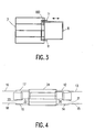
- FIG. 3 A top view of a part of in Fig. 2 shown embodiment is in Fig. 3 shown.
- the overlapping area 100 of the birdcage resonator 7 and the surface coil 8 can be seen.
- Denoted at 11 is a rail device mounted on both sides of the surface coil 8, which slides in a rail (not shown) attached to the birdcage resonator 7.
- the surface coil 8 can be displaced in the direction indicated by the double arrow relative to the birdcage resonator 7, whereby the size of the overlapping region 100 changes.
- FIG. 4 an alternative embodiment of an MR device according to the invention is shown.
- This includes a birdcage resonator 24 and a plurality of surface coils 12 to 23.
- the other surface coils 13th , 15, 16, 18, 21, 23 overlap each with the adjacent surface coil.
- the embodiment shown is suitable, for example, for producing MR images of an entire leg of a patient.
- the birdcage resonator 24 is arranged, for example, around the knee, the surface coils are distributed over the upper or lower leg. To reduce the number of receiving channels, the received signals from each two surface coils can also be received after processing with a combination circuit on a channel and are processed, so that seven receiving channels are required for this arrangement.
- any other embodiments are conceivable.
- a further birdcage resonator or a saddle coil arrangement may be provided in the end region, which surrounds the foot of the patient.
- the surface coil assembly may also consist of a combination of several different surface coils, wherein a plurality of surface coils, such as a loop and a butterfly coil are arranged one above the other and cover approximately the same area of the body surface.
- the design of the cylindrical coil arrangement may differ from the embodiments shown.
- the birdcage may likewise have an elliptical cross section and / or have a conductive end face and / or shoulder openings.
- a further additional decoupling between the surface coil and the cylindrical coil arrangement can be effected by a capacitive network between the two coil arrangements, if a sufficient improvement of the decoupling, for example for structural reasons, is not possible by changing the size of the overlapping area.
Landscapes
- Physics & Mathematics (AREA)
- Condensed Matter Physics & Semiconductors (AREA)
- General Physics & Mathematics (AREA)
- Magnetic Resonance Imaging Apparatus (AREA)
Claims (7)
- Appareil de RM pour un examen par RM comportant des moyens pour recevoir des signaux de RM provenant d'une plage d'examen traversée par un champ magnétique homogène stationnaire et par des champs magnétiques à gradient superposés, après excitation par un champ magnétique à haute fréquence au moyen d'un dispositif de bobines de RM, qui comprend un dispositif de bobines cylindriques (7) et un dispositif de bobines de surface (8), caractérisé en ce que le dispositif de bobines cylindriques (7) et le dispositif de bobines de surface (8) se recouvrent dans une zone de recouvrement (100) et en ce que l'appareil de RM comporte des moyens (11) pour faire varier la grandeur de la zone de recouvrement (100).
- Appareil de RM selon la revendication 1, caractérisé en ce que le dispositif de bobines cylindriques comprend au moins un résonateur à cage d'oiseau (7), un dispositif de bobines en sellette, un dispositif de bobines à solénoïde ou un dispositif à réseau en boucle.
- Appareil de RM selon la revendication 1 ou 2, caractérisé en ce que le dispositif de bobines de surface comprend au moins une bobine de surface (8, 9, 10) adaptée au moins localement à la surface du corps d'un patient (2).
- Appareil de RM selon l'une quelconque des revendications précédentes, caractérisé en ce que le dispositif de bobines cylindriques (7) est configuré de telle manière qu'il puisse entourer à faible distance la tête d'un patient (2), et en ce que le dispositif de bobines de surface (8) est configuré de telle manière qu'il puisse être adapté à la région du thorax et/ou de la nuque d'un patient (2).
- Appareil de RM selon l'une quelconque des revendications précédentes, caractérisé en ce que les moyens pour régler la grandeur de la zone de recouvrement (100) comprennent un dispositif sur rails (11), qui permet un déplacement du dispositif de bobines de surface (8, 9) par rapport au dispositif de bobines cylindriques (7).
- Appareil de RM selon l'une quelconque des revendications précédentes, caractérisé en ce que le dispositif de bobines de surface comprend des bobines de surface (8, 9, 10), dont la grandeur est variable.
- Dispositif de bobines de RM, comprenant un dispositif de bobines cylindriques (7) et un dispositif de bobines de surface (8), caractérisé en ce que le dispositif de bobines cylindriques (7) et le dispositif de bobines de surface (8) se recouvrent dans une zone de recouvrement (100) et en ce que le dispositif de bobines de RM comporte des moyens (11) pour faire varier la grandeur de la zone de recouvrement (100).
Applications Claiming Priority (2)
| Application Number | Priority Date | Filing Date | Title |
|---|---|---|---|
| DE19616464A DE19616464A1 (de) | 1996-04-25 | 1996-04-25 | MR-Gerät mit einer Zylinderspulenanordnung und einer Oberflächenspulenanordnung |
| DE19616464 | 1996-04-25 |
Publications (3)
| Publication Number | Publication Date |
|---|---|
| EP0803736A2 EP0803736A2 (fr) | 1997-10-29 |
| EP0803736A3 EP0803736A3 (fr) | 1998-04-15 |
| EP0803736B1 true EP0803736B1 (fr) | 2008-05-28 |
Family
ID=7792374
Family Applications (1)
| Application Number | Title | Priority Date | Filing Date |
|---|---|---|---|
| EP97201103A Expired - Lifetime EP0803736B1 (fr) | 1996-04-25 | 1997-04-14 | Appareil de RM avec un dispositif de bobines cylindriques et avec un dispositif de bobines de surface |
Country Status (4)
| Country | Link |
|---|---|
| US (1) | US5917324A (fr) |
| EP (1) | EP0803736B1 (fr) |
| JP (1) | JP4097738B2 (fr) |
| DE (2) | DE19616464A1 (fr) |
Families Citing this family (35)
| Publication number | Priority date | Publication date | Assignee | Title |
|---|---|---|---|---|
| US6027452A (en) | 1996-06-26 | 2000-02-22 | Vital Insite, Inc. | Rapid non-invasive blood pressure measuring device |
| WO1998037438A1 (fr) * | 1997-02-25 | 1998-08-27 | Advanced Imaging Research, Inc. | Ensemble bobinage haute frequence permettant une analyse de resonance |
| US6323648B1 (en) | 1997-11-26 | 2001-11-27 | Medrad, Inc. | Peripheral vascular array |
| US6711430B1 (en) | 1998-10-09 | 2004-03-23 | Insight Neuroimaging Systems, Inc. | Method and apparatus for performing neuroimaging |
| US6873156B2 (en) * | 1998-05-06 | 2005-03-29 | Insight Neuroimaging Systems, Llc | Method and apparatus for performing neuroimaging |
| JP2003511172A (ja) * | 1999-10-11 | 2003-03-25 | コーニンクレッカ フィリップス エレクトロニクス エヌ ヴィ | 感度の重なる領域を具備するmri−rfコイル |
| US6313633B1 (en) * | 1999-12-27 | 2001-11-06 | General Electric Company | Magnetic resonance imaging head coil |
| EP1326532A2 (fr) * | 2000-10-20 | 2003-07-16 | Insight Neuroimaging Systems, LLC | Procedes et appareil d'execution de neuro-imagerie |
| US6668184B1 (en) | 2000-12-19 | 2003-12-23 | Ge Medical Systems Global Technology Company, Llc | System for and method of synchronizing an image data receiver and an MR imaging acquisition slice |
| US20020103429A1 (en) * | 2001-01-30 | 2002-08-01 | Decharms R. Christopher | Methods for physiological monitoring, training, exercise and regulation |
| US20050283053A1 (en) * | 2002-01-30 | 2005-12-22 | Decharms Richard C | Methods for physiological monitoring, training, exercise and regulation |
| ATE539681T1 (de) * | 2001-01-30 | 2012-01-15 | R Christopher Decharms | Methoden für die physiologische überwachung, schulung und regulierung |
| US6487436B1 (en) | 2001-04-17 | 2002-11-26 | Ge Medical Systems Global Technology Company, Llc | Switchable field of view apparatus and method for magnetic resonance imaging |
| DE10126338A1 (de) * | 2001-05-30 | 2002-12-12 | Siemens Ag | Hochfrequenz-Spulenanordnung für ein Kernspintomographie-Gerät und Kernspintomorgraphie-Gerät |
| US6630829B1 (en) | 2002-04-22 | 2003-10-07 | Ge Medical Systems Global Technology Co., Llc | Gradient coil set capable of producing a variable field of view |
| US20040092809A1 (en) * | 2002-07-26 | 2004-05-13 | Neurion Inc. | Methods for measurement and analysis of brain activity |
| KR20040013704A (ko) * | 2002-08-08 | 2004-02-14 | 주식회사 아이솔테크놀로지 | 횡전자기파를 이용한 두부용 공명 코일 |
| US6762606B2 (en) * | 2002-11-22 | 2004-07-13 | Igc-Medical Advances, Inc. | Retracting MRI head coil |
| WO2004109300A2 (fr) * | 2003-06-03 | 2004-12-16 | Decharms R Christopher | Procedes de mesure de perturbations de signaux de resonance magnetique |
| WO2006055582A2 (fr) * | 2004-11-15 | 2006-05-26 | Christopher Decharms | Applications utilisant de la lumiere pour stimuler un tissu nerveux |
| US7538552B2 (en) * | 2005-01-24 | 2009-05-26 | Koninklijke Philips Electronics N.V. | Orthogonal coil for magnetic resonance imaging |
| JP5527731B2 (ja) * | 2007-04-16 | 2014-06-25 | ニューロアーム サージカル エル ティ ディー | レジストレーションに有用な方法、デバイス、およびシステム |
| US10076266B2 (en) | 2010-07-07 | 2018-09-18 | Aspect Imaging Ltd. | Devices and methods for a neonate incubator, capsule and cart |
| US10499830B2 (en) | 2010-07-07 | 2019-12-10 | Aspect Imaging Ltd. | Premature neonate life support environmental chamber for use in MRI/NMR devices |
| IL226488A (en) | 2013-05-21 | 2016-07-31 | Aspect Imaging Ltd | Baby crib |
| US11278461B2 (en) | 2010-07-07 | 2022-03-22 | Aspect Imaging Ltd. | Devices and methods for a neonate incubator, capsule and cart |
| US10794975B2 (en) | 2010-09-16 | 2020-10-06 | Aspect Imaging Ltd. | RF shielding channel in MRI-incubator's closure assembly |
| DE202011051313U1 (de) | 2010-09-16 | 2011-11-23 | Aspect Magnet Technologies Ltd. | Geschlossenes Lebensunterstützungssystem für Frühgeborene |
| JP6480455B2 (ja) | 2013-09-02 | 2019-03-13 | アスペクト イメージング リミテッド | 受動的に温度調節される新生児搬送用保育器 |
| US10383782B2 (en) | 2014-02-17 | 2019-08-20 | Aspect Imaging Ltd. | Incubator deployable multi-functional panel |
| US11287497B2 (en) | 2016-08-08 | 2022-03-29 | Aspect Imaging Ltd. | Device, system and method for obtaining a magnetic measurement with permanent magnets |
| US10224135B2 (en) | 2016-08-08 | 2019-03-05 | Aspect Imaging Ltd. | Device, system and method for obtaining a magnetic measurement with permanent magnets |
| US11988730B2 (en) | 2016-08-08 | 2024-05-21 | Aspect Imaging Ltd. | Device, system and method for obtaining a magnetic measurement with permanent magnets |
| US11052016B2 (en) | 2018-01-18 | 2021-07-06 | Aspect Imaging Ltd. | Devices, systems and methods for reducing motion artifacts during imaging of a neonate |
| EP3992656A1 (fr) * | 2020-10-27 | 2022-05-04 | Koninklijke Philips N.V. | Positionnement de bobines de radiofréquence dans des dispositifs d'imagerie par résonance magnétique |
Family Cites Families (18)
| Publication number | Priority date | Publication date | Assignee | Title |
|---|---|---|---|---|
| NL8603006A (nl) * | 1986-11-27 | 1988-06-16 | Philips Nv | Magnetisch resonantie apparaat met gestapeld oppervlakte spoelenstelsel. |
| NL8801018A (nl) * | 1988-04-20 | 1989-11-16 | Philips Nv | Magnetisch resonantie apparaat met ontkoppelde rf-spoelen. |
| JPH0168015U (fr) * | 1987-10-26 | 1989-05-01 | ||
| WO1989005115A1 (fr) * | 1987-12-07 | 1989-06-15 | General Electric Company | Imagerie a resonance magnetique nucleaire (rmn) avec des bobines multiples de surface |
| DE3816831A1 (de) * | 1988-05-18 | 1989-11-30 | Philips Patentverwaltung | Kernspinuntersuchungsgeraet mit einer hochfrequenzspulenanordnung |
| JPH01293863A (ja) * | 1988-05-24 | 1989-11-27 | Toshiba Corp | 磁気共鳴イメージング装置 |
| JPH02200243A (ja) * | 1989-01-30 | 1990-08-08 | Yokogawa Medical Syst Ltd | Mriのサーフェースコイル |
| JPH03103230A (ja) * | 1989-09-18 | 1991-04-30 | Toshiba Corp | 磁気共鳴イメージング装置 |
| JPH0420328A (ja) * | 1990-05-14 | 1992-01-23 | Toshiba Corp | Mri装置用受信コイル装置 |
| JPH0549613A (ja) * | 1991-01-11 | 1993-03-02 | Hitachi Medical Corp | 核磁気共鳴装置の受信コイル支持機構 |
| US5258717A (en) * | 1991-08-09 | 1993-11-02 | Medrad, Inc. | Geometrically isolated multiple port volume MRI receiving coil comprising multiple quadrature coils |
| US5510714A (en) * | 1991-08-09 | 1996-04-23 | Hitachi, Ltd. | Magnetic resonance imaging apparatus and RF coil employed therein |
| US5374890A (en) * | 1992-07-24 | 1994-12-20 | Picker International, Inc. | Simultaneous magnetic resonance imaging of multiple human organs |
| DE4225001C1 (de) * | 1992-07-29 | 1993-11-18 | Siemens Ag | Stereotaktische Zusatzeinrichtung für Kernspintomographen |
| US5285160A (en) * | 1992-08-06 | 1994-02-08 | U.S. Philips Corporation | Magnetic resonance apparatus comprising adjacently arranged RF coils systems |
| JP3216938B2 (ja) * | 1993-06-08 | 2001-10-09 | 株式会社日立製作所 | Mri用rfプローブ及び磁気共鳴撮影装置 |
| JP3411631B2 (ja) * | 1993-08-30 | 2003-06-03 | 株式会社日立メディコ | Rfプローブ及び磁気共鳴イメージング装置 |
| DE59509825D1 (de) * | 1994-08-03 | 2001-12-20 | Philips Corp Intellectual Pty | MR-Verfahren zur Bestimmung der Kernmagnetisierungsverteilung mit einer Oberflächenspulen-Anordnung |
-
1996
- 1996-04-25 DE DE19616464A patent/DE19616464A1/de not_active Withdrawn
-
1997
- 1997-04-14 EP EP97201103A patent/EP0803736B1/fr not_active Expired - Lifetime
- 1997-04-14 DE DE59712942T patent/DE59712942D1/de not_active Expired - Fee Related
- 1997-04-22 JP JP10479297A patent/JP4097738B2/ja not_active Expired - Fee Related
- 1997-04-23 US US08/842,290 patent/US5917324A/en not_active Expired - Fee Related
Also Published As
| Publication number | Publication date |
|---|---|
| EP0803736A2 (fr) | 1997-10-29 |
| DE59712942D1 (de) | 2008-07-10 |
| JPH1043161A (ja) | 1998-02-17 |
| US5917324A (en) | 1999-06-29 |
| EP0803736A3 (fr) | 1998-04-15 |
| DE19616464A1 (de) | 1997-11-06 |
| JP4097738B2 (ja) | 2008-06-11 |
Similar Documents
| Publication | Publication Date | Title |
|---|---|---|
| EP0803736B1 (fr) | Appareil de RM avec un dispositif de bobines cylindriques et avec un dispositif de bobines de surface | |
| DE4422782C2 (de) | Aktiv geschirmte transversale Gradientenspule für Kernspintomographiegeräte | |
| EP0462131B1 (fr) | Systeme magnetique | |
| DE102008006117B4 (de) | Magnetresonanzanlage, Antennensystem, Verfahren zum Aufbau einer Magnetresonanzanlage und Verfahren zur Erzeugung von Magnetresonanzaufnahmen | |
| EP0073375B1 (fr) | Dispositif à haute fréquence dans un appareil pour la résonance de spin nucléaire | |
| EP0586983B1 (fr) | Système de bobines à gradients pour un tomographe thérapeutique | |
| DE4424580C2 (de) | NMR-Scheibenspule | |
| DE3875863T2 (de) | Magnetisches resonanzgeraet mit gradientenspulensystem. | |
| DE19534387C2 (de) | Abschirmgradientenspule für ein Kernspin-Tomographiegerät und Kernspin-Tomographiegerät | |
| EP0142077B1 (fr) | Dispositif à haute fréquence dans un appareil pour la résonance de spin nucléaire avec une bobine de surface | |
| DE4030371A1 (de) | Quadraturoberflaechenspulenanordnung | |
| DE3411521A1 (de) | Nuklearmagnetische resonanzvorrichtung | |
| EP0141149A1 (fr) | Dispositif magnétique pour la tomographie à résonance de spin nucléaire, comportant une structure de blindage | |
| DE4142263C2 (de) | Gradientenspulensystem | |
| EP1275972A2 (fr) | Assemblage de bobines à haute fréquence pour un appareil à résonance magnétique | |
| DE69218500T2 (de) | Apparat mittels magnetischer Resonanz | |
| DE10255261A1 (de) | HF-Spulenanordnung für Magnetresonanz-Bildgerät | |
| DE69330822T2 (de) | Lokale transversale gradientenspule für die bildgebende magnetische resonanz | |
| DE19829298C2 (de) | Gradientenspulensystem für ein Kernspintomographiegerät | |
| EP0142079B1 (fr) | Dispositif à haute fréquence dans un appareil pour la résonance de spin nucléàire | |
| DE69311296T2 (de) | Vorrichtung zur Erzeugung eines Magnetfeldes für den Gebrauch zur Bilderzeugung mittels magnetischer Resonanz vom supraleitenden Typ | |
| EP0797103B1 (fr) | Assemblage d'aimants pour IRM avec deux volumes à imager separés | |
| DE69925956T2 (de) | Shimspulenanordnung und Gradientenspule mit Ausnehmungen für die Magnetresonanzbildgebung | |
| EP0177869B1 (fr) | Aménagement d'un aimant avec un dispositif d'écran pour une installation de tomographie de spin nucléaire | |
| DE60225039T2 (de) | Rf-spule mit zwei parallelen endleitern |
Legal Events
| Date | Code | Title | Description |
|---|---|---|---|
| PUAI | Public reference made under article 153(3) epc to a published international application that has entered the european phase |
Free format text: ORIGINAL CODE: 0009012 |
|
| AK | Designated contracting states |
Kind code of ref document: A2 Designated state(s): DE FR GB NL |
|
| PUAL | Search report despatched |
Free format text: ORIGINAL CODE: 0009013 |
|
| AK | Designated contracting states |
Kind code of ref document: A3 Designated state(s): DE FR GB NL |
|
| RAP3 | Party data changed (applicant data changed or rights of an application transferred) |
Owner name: KONINKLIJKE PHILIPS ELECTRONICS N.V. Owner name: PHILIPS PATENTVERWALTUNG GMBH |
|
| 17P | Request for examination filed |
Effective date: 19981015 |
|
| RAP3 | Party data changed (applicant data changed or rights of an application transferred) |
Owner name: KONINKLIJKE PHILIPS ELECTRONICS N.V. Owner name: PHILIPS CORPORATE INTELLECTUAL PROPERTY GMBH |
|
| RAP1 | Party data changed (applicant data changed or rights of an application transferred) |
Owner name: KONINKLIJKE PHILIPS ELECTRONICS N.V. Owner name: PHILIPS CORPORATE INTELLECTUAL PROPERTY GMBH |
|
| RAP1 | Party data changed (applicant data changed or rights of an application transferred) |
Owner name: KONINKLIJKE PHILIPS ELECTRONICS N.V. Owner name: PHILIPS INTELLECTUAL PROPERTY & STANDARDS GMBH |
|
| 17Q | First examination report despatched |
Effective date: 20070412 |
|
| GRAP | Despatch of communication of intention to grant a patent |
Free format text: ORIGINAL CODE: EPIDOSNIGR1 |
|
| GRAS | Grant fee paid |
Free format text: ORIGINAL CODE: EPIDOSNIGR3 |
|
| GRAA | (expected) grant |
Free format text: ORIGINAL CODE: 0009210 |
|
| AK | Designated contracting states |
Kind code of ref document: B1 Designated state(s): DE FR GB NL |
|
| REG | Reference to a national code |
Ref country code: GB Ref legal event code: FG4D Free format text: NOT ENGLISH |
|
| REF | Corresponds to: |
Ref document number: 59712942 Country of ref document: DE Date of ref document: 20080710 Kind code of ref document: P |
|
| PG25 | Lapsed in a contracting state [announced via postgrant information from national office to epo] |
Ref country code: NL Free format text: LAPSE BECAUSE OF FAILURE TO SUBMIT A TRANSLATION OF THE DESCRIPTION OR TO PAY THE FEE WITHIN THE PRESCRIBED TIME-LIMIT Effective date: 20080528 |
|
| NLV1 | Nl: lapsed or annulled due to failure to fulfill the requirements of art. 29p and 29m of the patents act | ||
| PLBE | No opposition filed within time limit |
Free format text: ORIGINAL CODE: 0009261 |
|
| STAA | Information on the status of an ep patent application or granted ep patent |
Free format text: STATUS: NO OPPOSITION FILED WITHIN TIME LIMIT |
|
| 26N | No opposition filed |
Effective date: 20090303 |
|
| GBPC | Gb: european patent ceased through non-payment of renewal fee |
Effective date: 20090414 |
|
| REG | Reference to a national code |
Ref country code: FR Ref legal event code: ST Effective date: 20091231 |
|
| PG25 | Lapsed in a contracting state [announced via postgrant information from national office to epo] |
Ref country code: DE Free format text: LAPSE BECAUSE OF NON-PAYMENT OF DUE FEES Effective date: 20091103 |
|
| PG25 | Lapsed in a contracting state [announced via postgrant information from national office to epo] |
Ref country code: GB Free format text: LAPSE BECAUSE OF NON-PAYMENT OF DUE FEES Effective date: 20090414 Ref country code: FR Free format text: LAPSE BECAUSE OF NON-PAYMENT OF DUE FEES Effective date: 20091222 |