EP0803968B1 - Dispositif de commande de la vitesse d'un moteur - Google Patents
Dispositif de commande de la vitesse d'un moteur Download PDFInfo
- Publication number
- EP0803968B1 EP0803968B1 EP95927952A EP95927952A EP0803968B1 EP 0803968 B1 EP0803968 B1 EP 0803968B1 EP 95927952 A EP95927952 A EP 95927952A EP 95927952 A EP95927952 A EP 95927952A EP 0803968 B1 EP0803968 B1 EP 0803968B1
- Authority
- EP
- European Patent Office
- Prior art keywords
- torque command
- speed
- value
- torque
- motor
- Prior art date
- Legal status (The legal status is an assumption and is not a legal conclusion. Google has not performed a legal analysis and makes no representation as to the accuracy of the status listed.)
- Expired - Lifetime
Links
Images


Classifications
-
- H—ELECTRICITY
- H02—GENERATION; CONVERSION OR DISTRIBUTION OF ELECTRIC POWER
- H02P—CONTROL OR REGULATION OF ELECTRIC MOTORS, ELECTRIC GENERATORS OR DYNAMO-ELECTRIC CONVERTERS; CONTROLLING TRANSFORMERS, REACTORS OR CHOKE COILS
- H02P5/00—Arrangements specially adapted for regulating or controlling the speed or torque of two or more electric motors
-
- H—ELECTRICITY
- H02—GENERATION; CONVERSION OR DISTRIBUTION OF ELECTRIC POWER
- H02P—CONTROL OR REGULATION OF ELECTRIC MOTORS, ELECTRIC GENERATORS OR DYNAMO-ELECTRIC CONVERTERS; CONTROLLING TRANSFORMERS, REACTORS OR CHOKE COILS
- H02P23/00—Arrangements or methods for the control of AC motors characterised by a control method other than vector control
- H02P23/16—Controlling the angular speed of one shaft
-
- H—ELECTRICITY
- H02—GENERATION; CONVERSION OR DISTRIBUTION OF ELECTRIC POWER
- H02P—CONTROL OR REGULATION OF ELECTRIC MOTORS, ELECTRIC GENERATORS OR DYNAMO-ELECTRIC CONVERTERS; CONTROLLING TRANSFORMERS, REACTORS OR CHOKE COILS
- H02P6/00—Arrangements for controlling synchronous motors or other dynamo-electric motors using electronic commutation dependent on the rotor position; Electronic commutators therefor
- H02P6/14—Electronic commutators
- H02P6/16—Circuit arrangements for detecting position
- H02P6/17—Circuit arrangements for detecting position and for generating speed information
Definitions
- This invention relates to a motor speed control device.
- a speed detector such as a tachometer generator is popularly employed.
- a system has been intensively employed in which a feedback speed signal is calculated from position data which is detected, for instance, with an encoder.
- v ⁇ y/Ts where ⁇ y is an increment during a sampling period Ts of a position signal.
- the phase of the speed signal thus calculated lags the actual speed, and, accuracy in a range of low speeds is considerably deteriorated.
- the latter problem that the accuracy in a range of low speeds is considerably deteriorated has been solved by obtaining a moving average of a plurality of past points.
- the phase lag is further increased.
- the phase lag is further increased. If the feedback control is carried out with the signal which lags in phase in the above-described manner, it is impossible to set the feedback gain to a high value, and accordingly the response speed becomes low.
- Japanese Patent Unexamined Publication No. Hei. 4-9767 has disclosed a method in which the speed at a calculation time instant is predicted and detected.
- the method is disadvantageous in the following points: In the method, the operating characteristics of the motor, and the torque command are not taken into account; that is, the prediction is carried out only on the basis of the position data detected by an encoder or the like, and therefore the predicted value may be different from the actual value.
- an object of the invention is to provide a motor speed control device in which a speed is predicted from position data detected with an encoder or the like, the operating characteristics of a motor, and a torque command, and a weighted moving average thereof is calculated, so that the feedback signal is less deteriorated in accuracy when the motor is in a range of low speeds, and has no phase lag.
- a motor speed control device in which, at the present time instant i, a motor position y(i-K) which was provided K•Ts before (where K ⁇ 0, and Ts is the sampling period) is detected to provide a detection signal, and feedback control is carried out with a motor speed feedback signal v fb which is calculated from the detection signal, which, according to the invention, comprises:
- reference numeral 5 designates a control calculator which receives a speed command and a feedback signal v fb , and outputs a torque command u; and 6, a unit including a torque controller, a motor, and a position detector.
- the unit 6 receives a torque instruction u(i) at the present time instant i, and outputs a motor position detection value y(i-K) which is obtained K•Ts before (K ⁇ 0, and Ts: sampling period).
- Reference numeral 2 denotes a calculator which obtains a speed feedback signal v fb according to the following Formula (1), and applies it to the control calculator 5.
- M and M' function as follows: The difference M-M' adjusts the phase of the speed feedback signal, the sum M+M' adjusts the speed resolution, and with M ⁇ M', a feedback signal has no phase lag.
- reference numeral 11 designates the predictor; 13, a memory for storing prediction coefficients A mn and B mn ; 14 and 15, memories for storing past torque command u and past position increment values ⁇ y which occur until the present time instant, respectively, and 16, a differential unit which obtains a position increment value ⁇ y from a position y.
- reference numeral 21 designates the predictor; 23, a memory for storing prediction coefficients A mn and B mn ; 24 and 25, memories for storing past torque instruction increment values ⁇ u and past position increment values ⁇ y which occurs until the present time instant, respectively, and 26 and 27, differential units which obtain increment values.
- the difference which is obtained by subtracting the disturbance torque u d from the torque command u may be employed as a torque command to obtain the speed prediction value.
- the torque command is determined from an operation which includes PID control and I-P control integration operations
- the resultant integration operation value may be employed as the aforementioned disturbance torque prediction value.
- the control calculator 5 calculates a torque command by PID operation, the difference obtained by subtracting an integration operation value from a torque instruction; that is, only the PD (proportional and differential) operation value is applied, as a torque command, to the predictor 1.
- FIG. 5 is a block diagram for a description of the case where, when a control calculator outputs the PI operation value subjected to primary filtering or n-th order filtering as a torque command u(i) at the next sampling period, the speed feedback signal v fb (i) is obtained according to Formula (11).
- an integration value provided one period before is employed as a disturbance torque u d ; however, it may be subjected to filtering to obtain a disturbance torque u d .
- a speed v(i) is obtained according to ⁇ y(i)/T s ; however, the invention is not limited thereto or thereby. That is, it may be obtained according to a conventional speed calculating method such as a method of using a speed detector, or a method of calculating the speed by measuring the pulse duration time of an encoder.
- the speed feedback signal is employed which is less deteriorated in accuracy when the motor is in a range of low speeds, and has no phase lag.
- the motor speed control device is high in feedback loop gain, and high in response characteristic.
- the invention is applied to a motor speed control device.
Landscapes
- Engineering & Computer Science (AREA)
- Power Engineering (AREA)
- Control Of Electric Motors In General (AREA)
- Feedback Control In General (AREA)
Claims (6)
- Dispositif de contrôle de vitesse de moteur dans lequel, à un instant présent i, une position du moteur y qui existait K.Ts auparavant, où K ≥ 0, et Ts étant une période d'échantillonnage, est détectée pour fournir un signal de détection et une commande de rétroaction est effectuée à l'aide d'un signal de rétroaction de vitesse du moteur Vfb qui est calculé à partir dudit signal de détection, caractérisé en ce qu'il comporte :des moyens (5) pour calculer une commande de couple u(i) à partir d'une commande de vitesse et dudit signal de rétroaction de moteur Vfb ;des moyens (4) pour calculer une vitesse v(i-K) à partir de ladite position y(1-K) ;des moyens (3) afin de mémoriser ladite vitesse v(i-m) (où m = K, ..., M') qui apparaít entre un M'-ième échantillonnage passé jusqu'à un instant i-K ;un prédicteur (1) pour obtenir une valeur de prédiction de vitesse v*(i+m), où m = -K+1, ..., M, à un M-ième échantillonnage futur à partir d'un modèle caractéristique dynamique du moteur, de ladite commande de couple u(i) et de ladite position y(i-K) ; etdes moyens (2) pour calculer ledit signal de rétroaction de vitesse à partir de la formule suivante :où Wm et W'm sont des coefficients de pondération.

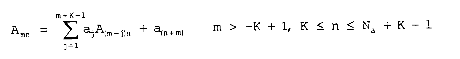
- Dispositif de contrôle de vitesse de moteur selon la revendication 1, caractérisé en ce que ledit prédicteur comporte :des moyens pour obtenir une valeur d'incrément de position Δy à partir d'une position y, où Δ représente une valeur d'incrément pour une période d'échantillonnage Ts ;des moyens pour déterminer, en fonction d'un modèle de fonction de transfert, à partir d'une commande de couple u jusqu'à une valeur d'incrément de position Δy, Gv(z) = (b1z-1 + ... + bNbz-Nb)/(1-a1z-1 - ... - aNaz-Na), des coefficients de prédiction Amn et Bmn selon les formules suivantes
 où an = 0, n > Na, et bn = 0, n < 1 et n > Nb ;
 des moyens pour mémoriser des valeurs de commande de couple et d'incrément de position passées jusqu'à un instant présent ; etdes moyens pour obtenir, en fonction desdits coefficients de prédiction, des valeurs de commande de couple et d'incrément de position, ladite valeur de prédiction de vitesse selon les formules suivantes :
- Dispositif de contrôle de vitesse de moteur selon la revendication 2, caractérisé en ce qu'il comporte :des moyens pour utiliser, en tant que ladite grandeur Bm0, les formules suivantes :

- Dispositif de contrôle de vitesse de moteur selon la revendication 1, caractérisé en ce que ledit prédicteur comporte :des moyens pour obtenir une valeur d'incrément de position Δy et une valeur d'incrément de commande de couple Δu à partir d'une position y et d'une commande de couple u;des moyens pour déterminer, en fonction d'un modèle de fonction de transfert, à partir d'un incrément de couple Δu jusqu'à une valeur d'incrément de position Ay, Gp(z) = (b1z-1 + ... + bNbz-Nb)/(1-a1z-1 - ... - aNaz-Na), des coefficients de prédiction Amn et Bmn selon les formules suivantes, et mémoriser lesdits coefficients de prédiction ainsi déterminés :
 où an = 0, n > Na, et bn = 0, n < 1 et n > Nb ;
 des moyens pour mémoriser des valeurs d'incrément de commande de couple et des valeurs d'incrément de position passées jusqu'à un présent instant ; etdes moyens pour obtenir, en fonction de coefficients de prédiction, desdites valeurs de commande de couple, et des commandes d'incrément de position, ladite valeur de prédiction de vitesse selon les formules suivantes:
- Dispositif de contrôle de vitesse de moteur selon la revendication 1, caractérisé en ce qu'il comporte :des moyens afin d'obtenir la valeur de détection ou la valeur de prédiction d'un couple parasite ud : etdes moyens pour obtenir une valeur de prédiction de vitesse avec la différence considérée comme une commande de couple qui est obtenue par soustraction dudit couple parasite ud de ladite instruction de couple u.
- Dispositif de contrôle de vitesse de moteur selon la revendication 5, caractérisé en ce que, dans le cas où une commande de couple est déterminée par une opération comprenant une commande PID ou une opération d'intégration de contrôle I-P, une valeur d'opération d'intégration est utilisée en tant que ledit couple parasite ud.
Applications Claiming Priority (3)
| Application Number | Priority Date | Filing Date | Title |
|---|---|---|---|
| JP204559/94 | 1994-08-05 | ||
| JP20455994A JP3296527B2 (ja) | 1994-08-05 | 1994-08-05 | モータ速度制御装置 |
| PCT/JP1995/001534 WO1996004708A1 (fr) | 1994-08-05 | 1995-08-02 | Dispositif de commande de la vitesse d'un moteur |
Publications (3)
| Publication Number | Publication Date |
|---|---|
| EP0803968A1 EP0803968A1 (fr) | 1997-10-29 |
| EP0803968A4 EP0803968A4 (fr) | 1997-10-29 |
| EP0803968B1 true EP0803968B1 (fr) | 1999-01-13 |
Family
ID=16492489
Family Applications (1)
| Application Number | Title | Priority Date | Filing Date |
|---|---|---|---|
| EP95927952A Expired - Lifetime EP0803968B1 (fr) | 1994-08-05 | 1995-08-02 | Dispositif de commande de la vitesse d'un moteur |
Country Status (7)
| Country | Link |
|---|---|
| US (1) | US5834912A (fr) |
| EP (1) | EP0803968B1 (fr) |
| JP (1) | JP3296527B2 (fr) |
| KR (1) | KR100352024B1 (fr) |
| CN (1) | CN1047700C (fr) |
| DE (1) | DE69507340T2 (fr) |
| WO (1) | WO1996004708A1 (fr) |
Families Citing this family (19)
| Publication number | Priority date | Publication date | Assignee | Title |
|---|---|---|---|---|
| US6215270B1 (en) | 1996-12-04 | 2001-04-10 | Kabushiki Kaisha Yaskawa Denki | Synchronous control device |
| FI111932B (fi) * | 1997-06-05 | 2003-10-15 | Kone Corp | Menetelmä hissin nopeuden säätöön ja hissijärjestelmä |
| JP3900219B2 (ja) * | 1997-10-24 | 2007-04-04 | 株式会社安川電機 | 電動機速度制御装置および同装置のゲイン設定方法 |
| US6075332A (en) * | 1998-05-14 | 2000-06-13 | Mccann; Roy A. | Predictive conductive angle motor control system for brake-by-wire application |
| JP3859115B2 (ja) * | 1999-07-26 | 2006-12-20 | セイコーエプソン株式会社 | プリンタ用モータの制御装置および制御方法ならびに制御プログラムを記録した記録媒体 |
| WO2001020767A1 (fr) * | 1999-09-17 | 2001-03-22 | Delphi Technologies, Inc. | Regulation de moteur a aimant permanent a faible niveau d"ondulation |
| JP2002091570A (ja) * | 2000-09-20 | 2002-03-29 | Yaskawa Electric Corp | サーボ制御方法 |
| JP4143437B2 (ja) * | 2003-02-20 | 2008-09-03 | アルプス電気株式会社 | 力覚付与型入力装置 |
| US7368886B2 (en) * | 2004-05-14 | 2008-05-06 | General Motors Corporation | Method of testing motor torque integrity in a hybrid electric vehicle |
| CN100489338C (zh) * | 2004-09-24 | 2009-05-20 | 株式会社小松制作所 | 齿轮驱动控制装置、齿轮驱动控制方法、旋转控制装置、以及建设机械 |
| JP2006201148A (ja) | 2004-12-22 | 2006-08-03 | Toshiba Mach Co Ltd | 信号処理装置、信号処理方法、信号処理プログラム、信号処理プログラムを記録した記録媒体、速度検出装置、サーボ機構 |
| US7376525B2 (en) * | 2005-05-10 | 2008-05-20 | Newport Corporation | Apparatus and method for estimation of initial phase of a brushless motor |
| WO2006120547A1 (fr) * | 2005-05-11 | 2006-11-16 | Toyota Jidosha Kabushiki Kaisha | Unite de commande a dispositif electrique rotatif comprenant un tel dispositif |
| JP4622863B2 (ja) * | 2006-01-10 | 2011-02-02 | トヨタ自動車株式会社 | モータの制御装置 |
| DE102009054603A1 (de) * | 2009-12-14 | 2011-06-16 | Robert Bosch Gmbh | Verfahren zur Steuerung eines Elektromotors |
| JP6289044B2 (ja) * | 2013-11-15 | 2018-03-07 | オリンパス株式会社 | 観察装置 |
| CN106483990B (zh) * | 2016-12-20 | 2019-06-14 | 南京埃斯顿自动化股份有限公司 | 一种电机控制方法 |
| CN110568210A (zh) * | 2019-09-06 | 2019-12-13 | 深圳臻宇新能源动力科技有限公司 | 一种转速预测方法、系统及车辆 |
| JP6791515B1 (ja) * | 2019-10-16 | 2020-11-25 | 多摩川精機株式会社 | 回転機器制御システム及びエンコーダ |
Family Cites Families (15)
| Publication number | Priority date | Publication date | Assignee | Title |
|---|---|---|---|---|
| JPS57203958A (en) * | 1981-06-09 | 1982-12-14 | Fanuc Ltd | Detecting method for velocity of induction motor |
| JPS596782A (ja) * | 1982-07-01 | 1984-01-13 | Hitachi Ltd | 電動機のデイジタル速度制御装置 |
| JPS59214921A (ja) * | 1983-05-20 | 1984-12-04 | Yaskawa Electric Mfg Co Ltd | パルス周波数検出方式 |
| JPS61277391A (ja) * | 1985-05-31 | 1986-12-08 | Fuji Electric Co Ltd | 状態観測器 |
| JPS62260574A (ja) * | 1986-05-06 | 1987-11-12 | Mitsubishi Electric Corp | モ−タの回転速度検出方法 |
| JPS63190583A (ja) * | 1987-01-29 | 1988-08-08 | Fanuc Ltd | 速度制御方式 |
| JPH01107687A (ja) * | 1987-10-20 | 1989-04-25 | Matsushita Electric Ind Co Ltd | モータの制御方法 |
| JPH02159990A (ja) * | 1988-12-10 | 1990-06-20 | Fanuc Ltd | サーボモータの速度制御方式 |
| JP2728499B2 (ja) * | 1989-05-19 | 1998-03-18 | 株式会社日立製作所 | 電動機の速度制御装置 |
| JP2827446B2 (ja) * | 1990-04-27 | 1998-11-25 | 株式会社明電舎 | 電動機の速度検出方法 |
| TW221535B (fr) * | 1991-05-20 | 1994-03-01 | Meidensha Electric Mfg Co Ltd | |
| JPH0530772A (ja) * | 1991-07-23 | 1993-02-05 | Sharp Corp | サーボ制御装置 |
| JPH05260777A (ja) * | 1992-03-12 | 1993-10-08 | Meidensha Corp | 電動機の速度検出方法 |
| JPH06162614A (ja) * | 1992-11-13 | 1994-06-10 | Sony Corp | 周波数電圧変換器及び速度検出装置 |
| JP3166446B2 (ja) * | 1993-10-26 | 2001-05-14 | 株式会社明電舎 | 速度推定オブザーバ |
-
1994
- 1994-08-05 JP JP20455994A patent/JP3296527B2/ja not_active Expired - Fee Related
-
1995
- 1995-08-02 EP EP95927952A patent/EP0803968B1/fr not_active Expired - Lifetime
- 1995-08-02 DE DE69507340T patent/DE69507340T2/de not_active Expired - Fee Related
- 1995-08-02 CN CN95195292A patent/CN1047700C/zh not_active Expired - Fee Related
- 1995-08-02 US US08/776,672 patent/US5834912A/en not_active Expired - Lifetime
- 1995-08-02 WO PCT/JP1995/001534 patent/WO1996004708A1/fr not_active Ceased
- 1995-08-02 KR KR1019970700765A patent/KR100352024B1/ko not_active Expired - Fee Related
Also Published As
| Publication number | Publication date |
|---|---|
| US5834912A (en) | 1998-11-10 |
| CN1158675A (zh) | 1997-09-03 |
| CN1047700C (zh) | 1999-12-22 |
| DE69507340T2 (de) | 1999-05-27 |
| EP0803968A1 (fr) | 1997-10-29 |
| JP3296527B2 (ja) | 2002-07-02 |
| KR100352024B1 (ko) | 2002-12-18 |
| KR970705223A (ko) | 1997-09-06 |
| WO1996004708A1 (fr) | 1996-02-15 |
| DE69507340D1 (de) | 1999-02-25 |
| JPH0851788A (ja) | 1996-02-20 |
| EP0803968A4 (fr) | 1997-10-29 |
Similar Documents
| Publication | Publication Date | Title |
|---|---|---|
| EP0803968B1 (fr) | Dispositif de commande de la vitesse d'un moteur | |
| US4680518A (en) | Servomotor velocity control method | |
| US11005403B2 (en) | Motor control system and method based on current feedback signal | |
| US4695780A (en) | Servomotor velocity control system | |
| EP0514847A2 (fr) | Système et méthode pour commander la vitesse d'un moteur électrique dans une plage de vitesse extrêmement basse à l'aide d'un codeur d'impulsions rotatif | |
| EP0241563B1 (fr) | Systeme de regulation de vitesse | |
| US6310456B1 (en) | Control system and method | |
| EP1868289A1 (fr) | Dispositif de commande de moteur | |
| US6215270B1 (en) | Synchronous control device | |
| EP0417774B1 (fr) | Système de commande à rétroaction | |
| CA2110208C (fr) | Methode servant a evaluer l'inertie d'un systeme a deux masses durant la regulation de la vitesse, et systeme connexe | |
| JP3551345B2 (ja) | 同期制御装置 | |
| US5880566A (en) | Absolute angular position calculation apparatus for a rotating motor and velocity control apparatus adopting the same | |
| JPH06318102A (ja) | センサ補償装置 | |
| EP1441267A1 (fr) | Procede de commande d'un appareil de servocommande | |
| JP3882311B2 (ja) | 飛しょう体の誘導制御装置 | |
| JPH11285730A (ja) | 帯状材の張力制御方法及び装置 | |
| JP2000184763A (ja) | ロール駆動用電動機の速度制御方法 | |
| JP3213796B2 (ja) | サーボモータ制御装置 | |
| JP4228157B2 (ja) | イナーシャ同定方法および装置 | |
| JP2002354861A (ja) | モータ速度制御装置 | |
| JPS62252561A (ja) | テ−プ移送装置の制御方法 | |
| JPH09247975A (ja) | モータドライブ装置 | |
| JPH07210213A (ja) | 制御装置 | |
| JPH08339207A (ja) | 制御装置 |
Legal Events
| Date | Code | Title | Description |
|---|---|---|---|
| PUAI | Public reference made under article 153(3) epc to a published international application that has entered the european phase |
Free format text: ORIGINAL CODE: 0009012 |
|
| 17P | Request for examination filed |
Effective date: 19970130 |
|
| A4 | Supplementary search report drawn up and despatched | ||
| AK | Designated contracting states |
Kind code of ref document: A4 Designated state(s): CH DE GB LI Kind code of ref document: A1 Designated state(s): CH DE GB LI |
|
| GRAG | Despatch of communication of intention to grant |
Free format text: ORIGINAL CODE: EPIDOS AGRA |
|
| 17Q | First examination report despatched |
Effective date: 19980316 |
|
| GRAG | Despatch of communication of intention to grant |
Free format text: ORIGINAL CODE: EPIDOS AGRA |
|
| GRAH | Despatch of communication of intention to grant a patent |
Free format text: ORIGINAL CODE: EPIDOS IGRA |
|
| GRAH | Despatch of communication of intention to grant a patent |
Free format text: ORIGINAL CODE: EPIDOS IGRA |
|
| GRAA | (expected) grant |
Free format text: ORIGINAL CODE: 0009210 |
|
| AK | Designated contracting states |
Kind code of ref document: B1 Designated state(s): CH DE GB LI |
|
| REG | Reference to a national code |
Ref country code: CH Ref legal event code: EP |
|
| REF | Corresponds to: |
Ref document number: 69507340 Country of ref document: DE Date of ref document: 19990225 |
|
| REG | Reference to a national code |
Ref country code: CH Ref legal event code: NV Representative=s name: BOVARD AG PATENTANWAELTE |
|
| PLBE | No opposition filed within time limit |
Free format text: ORIGINAL CODE: 0009261 |
|
| STAA | Information on the status of an ep patent application or granted ep patent |
Free format text: STATUS: NO OPPOSITION FILED WITHIN TIME LIMIT |
|
| 26N | No opposition filed | ||
| REG | Reference to a national code |
Ref country code: GB Ref legal event code: IF02 |
|
| REG | Reference to a national code |
Ref country code: GB Ref legal event code: 746 Effective date: 20050407 |
|
| PGFP | Annual fee paid to national office [announced via postgrant information from national office to epo] |
Ref country code: GB Payment date: 20050727 Year of fee payment: 11 |
|
| PGFP | Annual fee paid to national office [announced via postgrant information from national office to epo] |
Ref country code: DE Payment date: 20050728 Year of fee payment: 11 |
|
| PGFP | Annual fee paid to national office [announced via postgrant information from national office to epo] |
Ref country code: CH Payment date: 20050815 Year of fee payment: 11 |
|
| PG25 | Lapsed in a contracting state [announced via postgrant information from national office to epo] |
Ref country code: LI Free format text: LAPSE BECAUSE OF NON-PAYMENT OF DUE FEES Effective date: 20060831 Ref country code: CH Free format text: LAPSE BECAUSE OF NON-PAYMENT OF DUE FEES Effective date: 20060831 |
|
| PG25 | Lapsed in a contracting state [announced via postgrant information from national office to epo] |
Ref country code: DE Free format text: LAPSE BECAUSE OF NON-PAYMENT OF DUE FEES Effective date: 20070301 |
|
| REG | Reference to a national code |
Ref country code: CH Ref legal event code: PL |
|
| GBPC | Gb: european patent ceased through non-payment of renewal fee |
Effective date: 20060802 |
|
| PG25 | Lapsed in a contracting state [announced via postgrant information from national office to epo] |
Ref country code: GB Free format text: LAPSE BECAUSE OF NON-PAYMENT OF DUE FEES Effective date: 20060802 |