EP0803982A1 - Elektronisches System organisiert in einem matrizenförmigen Netz von funktionellen zellen - Google Patents
Elektronisches System organisiert in einem matrizenförmigen Netz von funktionellen zellen Download PDFInfo
- Publication number
- EP0803982A1 EP0803982A1 EP97400935A EP97400935A EP0803982A1 EP 0803982 A1 EP0803982 A1 EP 0803982A1 EP 97400935 A EP97400935 A EP 97400935A EP 97400935 A EP97400935 A EP 97400935A EP 0803982 A1 EP0803982 A1 EP 0803982A1
- Authority
- EP
- European Patent Office
- Prior art keywords
- cells
- cell
- code
- organ
- network
- Prior art date
- Legal status (The legal status is an assumption and is not a legal conclusion. Google has not performed a legal analysis and makes no representation as to the accuracy of the status listed.)
- Granted
Links
Images






Classifications
-
- H—ELECTRICITY
- H03—ELECTRONIC CIRCUITRY
- H03K—PULSE TECHNIQUE
- H03K19/00—Logic circuits, i.e. having at least two inputs acting on one output; Inverting circuits
- H03K19/02—Logic circuits, i.e. having at least two inputs acting on one output; Inverting circuits using specified components
- H03K19/173—Logic circuits, i.e. having at least two inputs acting on one output; Inverting circuits using specified components using elementary logic circuits as components
- H03K19/177—Logic circuits, i.e. having at least two inputs acting on one output; Inverting circuits using specified components using elementary logic circuits as components arranged in matrix form
- H03K19/17748—Structural details of configuration resources
- H03K19/17764—Structural details of configuration resources for reliability
-
- G—PHYSICS
- G06—COMPUTING OR CALCULATING; COUNTING
- G06N—COMPUTING ARRANGEMENTS BASED ON SPECIFIC COMPUTATIONAL MODELS
- G06N3/00—Computing arrangements based on biological models
- G06N3/12—Computing arrangements based on biological models using genetic models
- G06N3/126—Evolutionary algorithms, e.g. genetic algorithms or genetic programming
-
- H—ELECTRICITY
- H03—ELECTRONIC CIRCUITRY
- H03K—PULSE TECHNIQUE
- H03K19/00—Logic circuits, i.e. having at least two inputs acting on one output; Inverting circuits
- H03K19/02—Logic circuits, i.e. having at least two inputs acting on one output; Inverting circuits using specified components
- H03K19/173—Logic circuits, i.e. having at least two inputs acting on one output; Inverting circuits using specified components using elementary logic circuits as components
- H03K19/177—Logic circuits, i.e. having at least two inputs acting on one output; Inverting circuits using specified components using elementary logic circuits as components arranged in matrix form
- H03K19/17704—Logic circuits, i.e. having at least two inputs acting on one output; Inverting circuits using specified components using elementary logic circuits as components arranged in matrix form the logic functions being realised by the interconnection of rows and columns
Definitions
- the present invention relates to programmable electronic integrated systems comprising, to achieve its functionalities, a matrix network of cells, all identical and configurable for the functions which they must perform.
- Such systems can be provided with various intrinsic fault tolerance functions of the cells thanks to their capacity to adapt themselves to the fault in order to be able to perpetuate their functionalities.
- a network of this type is described in European patent application No. 94.81 0292.6 filed on May 5, 1994 in the name of the Applicant and entitled: "Electronic system organized in a matrix network of cells".
- cells are grouped into a network which includes means for propagating a "genome” composed of "genes” through the cells of the network in order to activate them for the functions they have to fulfill in the system.
- the term “gene” is understood here to mean a binary code word comprising all the information necessary to place a given cell in the desired functional configuration.
- the invention aims to improve the network described in the aforementioned patent application in order to reduce the size of the genome, reduce the influence of breakdowns by limiting them to the affected organ and, more generally, allow better organizational flexibility of the functions to be performed by the network.
- the subject of the invention is therefore a matrix network composed of cells all of identical construction and in which each cell is assigned a code word which defines the function which it must perform within the network, said network comprising means which , in order to configure the cells, translate iteratively in each of said cells a genome formed by a train of said successive code words, characterized in that it comprises at least one individualized functional organ composed of a plurality of said cells which are all characterized by a first predetermined code forming part of said word of code and formed by a number identifying said organ so that these cells can collectively ensure the functionality of said organ, said organ cells being distributed in a first group of so-called internal cells defined by a first predetermined value of a second code or status code also forming part of said code word, and in a second group of cells called membrane and defined by a second predetermined value of said second code, said first group of cells ensuring the functionality of said organ and said second group of cells forming membrane capable of functionally isolating said first group of cells ules from the rest of the
- the cells of the functional organ can be configured and identified with a relatively small volume of information, which makes it possible to reduce the size of the genome necessary to configure the network. Furthermore, it becomes possible to ensure within each organ a better flexibility of management of the functionality in particular by the faculty of self-repair with which a functional organ can be endowed.
- the terms "West” and “South” (and possibly, “North” and “East”) used hereinafter designate here, arbitrarily and for the convenience of the description, the directions in the matrix network, comprising a very large number of cells to be represented located in a plane and located like road maps for example, according to the cardinal directions of the compass rose.
- the physical arrangement of the network according to the invention may be different from such a planar arrangement, the different parts of the network being able to be produced, for example, on several integrated circuit chips arranged according to any design depending on the needs. It is also possible to design based on the concept of the invention of three-dimensional networks involving addressing accordingly.
- FIG. 1 a matrix network R according to the invention (FIG. 1) designed as a two-dimensional network. It therefore comprises a plurality of juxtaposed cells, all identical and arranged in the example along two perpendicular axes X and Y. Thus, each cell is assigned a global address consisting of a value in X and a value in Y.
- the network R is controlled by a processor P which makes it possible to configure the network at initialization, to reconfigure it if necessary during its operation and, possibly, to exchange with it control and information signals relating to the tasks which must be accomplished by the network during its operation.
- the network R has a certain hierarchy among the cells.
- functional organs are delimited therein by the configuration of the cells during initialization.
- FIG. 1 three of these members 01, 02 and 03 are shown by way of example, this number obviously being in no way limiting.
- Each of these organs 01, 02, 03 ... We have the property of being organically distinct from the other organs and / or cells of the network and thus forming an autonomous functional entity capable of performing a specific function, of exchanging electrical signals with the rest of the network and / or with the processor P, and to proceed itself to the management of breakdowns which can strike the cells of which it is composed.
- each organ comprises a zygote, Z1, Z2, ..., Zn, which is the basic cell of the organ from which, in particular to initialization of the network, the organ will be developed.
- Each organ also includes a group of cells, such as MO1, MO2, ..., MOn, forming what is called a membrane in the following description.
- a membrane goes around an organ to functionally isolate it from the rest of the R network.
- Membrane cells are configured (i.e. functionally organized), using the gene that corresponds to them, to so as to allow them to ensure the exchange with the outside (that is to say with the rest of the network and / or with the processor P).
- the cells are assigned a local address which defines its implantation in this organ relative to the zygote Z1, Z2, ..., Zn thereof.
- the code words corresponding to these cells therefore do not contain an address value corresponding to their global address.
- the genome To initialize the R network, the genome must traverse all of its cells which, in the embodiment which will be described below, is carried out in a serial manner by shifting the genome in the cells under the action of a signal general clock (not shown) which is provided by processor P.
- a network code word according to the invention is as follows: ⁇ status> ⁇ MHCcode> ⁇ @X> ⁇ @Y> ⁇ x> ⁇ y> ⁇ gene> in which ⁇ statut> defines the status information of the cell, ⁇ MHC code> (acronym borrowed from cell biology for "Major Histocompatibility Complex") the membership information for a given organ, ⁇ @X> and ⁇ @Y> the global address of the cell, ⁇ x> and ⁇ y> its local address and, finally, ⁇ gene> the functionality of this cell.
- the gene is used to configure the cell, preferably, as described in the aforementioned patent application. We will therefore not return to this in the present description.
- FIG. 2 represents a very simplified diagram of a cell of the network R according to the invention. It is designated by the general reference C x, y . All cells in the network have the same construction.
- the cell has a shift register 1 through which the genome can pass.
- this transition is serial and takes place under the control of the clock signal generated by the general clock located in the processor P.
- the shift register 1 has its input 2 which communicates with the output of the shift register of the South and West cells and has two communicating outputs 3a and 3b, respectively, with the entries of the shift registers of the North and East cells.
- the positions of the shift register 1 are logically in communication with logic analysis modules which are responsible for examining the genome transferred into register 1 and for taking therein the information intended for the cell considered.
- the cell includes a sequencer 4 responsible for implementing the different phases of the sequencing, as will appear in the following description.
- the cell also comprises a module 5 in which the genes of all or part of the other cells of the organ can be stored.
- the cell also includes a programmable functional part 6 preferably operating in the manner described in the aforementioned patent application. We will therefore not return to this in the present description.
- each cell also includes a part 7 dedicated to fault management which will receive the error signals from the different blocks constituting the cell, preferably operating in the manner described in the aforementioned patent application. We will therefore not return to this in the present description.
- each cell includes registers 8 and 9, respectively, of global and local addresses as well as a register of CMH code 10.
- FIGS. 3, 3A and 3B show a simplified diagram of an exemplary embodiment of such circuits forming part of the cell C X, Y , it being understood that they are found identically in all the cells of the network A. Some of these circuits belong to sequencer 4, others to logic blocks M1 to M7 or to module 5 of the cell.
- One of the circuits is responsible, when starting the circuit (Power-On-Reset signal), for calculating the global address @X and @Y of the cell C x, y , then when loading an organ, the same circuit is used to calculate the local address ⁇ X and ⁇ Y of cell C x, y .
- the calculation of the global addresses is advantageously carried out using a redundancy method making it possible to verify the transfers and the calculations of the values of the addresses for all the cells. The calculation can be performed in series or in parallel.
- the calculation of the global addresses is triggered, at the initialization of the network R, by the processor P (FIG. 1) which produces, for this purpose, a reset signal (Power-On-Reset). This signal causes the address of the "first" cell of the network to be calculated, which in the example has the address 0.0 (Fig. 4).
- the calculation of the global addresses is then carried out step by step in all the cells as follows.
- the global address of cell C X, Y is calculated from those of adjacent cells C X-1, Y and C X, Y-1 of which, in FIG. 3, only the registers of global address 8.
- the circuit 12 comprises, for loading the X value of the global address, a multiplexer 13 controlled by the signal BordSud.
- the input "0" of the muliplexer 13, valid when the signal BordSud 0, is connected to the part X of the register 8 of the cell C x, y-1 .
- the calculation is performed from the West cell (C x-1, y ) and then requires an incrementation (thanks to the incrementer 14).
- the two values of X are sent to the block 15 for checking consistency. If the two values are different, there is an anomaly in the transfer of the addresses or in the calculation. Thanks to this redundancy of the address calculation, the processor P can, by means which are not described here, take measures to remedy an anomaly, possibly by eliminating on the functional level of the network the cell in which the error has been noted.
- the values of the BordSud and BordWest signals can, for example, be defined during network construction or by the P processor.
- FIG. 4 shows the extreme southwest part of a network R in which the cells have been loaded with their global address, the initial address of the extreme southwest cell here being chosen to be 0.0.
- FIG. 4 also shows the very first operation of the step of the process of creation of the organs of the network, step which will take place immediately after the loading of the global addresses in the cells, namely the passage of the genome through the registers 1 of all cells.
- the step is triggered by the emission of a signal which is emitted by the processor P as soon as the loading of the global addresses is completed and transferred from cell to cell on conductors 11a and 11b being in each cell (see also the figure 2).
- This signal triggers the operation of the sequencers 4 of all the cells.
- FIG. 4 shows the situation at the end of the first clock cycle of this step.
- the shift register 1 of the cell of global address 0,0 received the first digit of the genome which here has the value "1".
- the cycle counters of all cells mark the position "1".
- the shift register 1 of cell 0.0 which received the first digit, the other shift registers are still empty.
- the part of the network comprising the nine cells which are at its extreme southwest corner.
- the address cell 0.0 has just received the entire first code word, which in the example requires 58 clock cycles. Under these conditions, the status code of this code word is found, in the shift register 1, at a position which allows it to be analyzed by the module M1 of the address cell 0.0.
- the logic module M1 comprises a decoder 20 which delivers the control signals from the sequencer as a function of the different values of the code ⁇ statut>. For example, when ⁇ statut> is 1, the command START is produced.
- the logic module M1 also includes two loading control elements 21 and 22 which make it possible to modify the status code for, respectively, the neighboring cells North and East of the cell C x, y .
- two status registers 20a and 20b receive a copy of the status code.
- the logic module M2 includes a comparator 25 receiving, on one of its inputs, the code CMH from the register 10 and, on the other input, the value "0". This comparator 25 delivers a logic "1" (signalCMHFree at "1") at its output when the values applied to its inputs are both equal. This means that the cell is still free.
- the logic module M2 also includes a comparator 26 receiving, on one of its inputs, the code CMH from the register 10 and, on the other input, the value coming from the CMH code passing through the shift register 1.
- This comparator 26 delivers a logic "1" (CMHIdent signal at "1") at its output when the values applied to its inputs are both equal. This means that the code word is compatible with the organ.
- the M2 module further comprises a loading control element 27 which allows the loading of the register 10 with the organ number CMH as a function of the signal Load_CMH (FIG. 3).
- the global addresses @X and @Y of code word No. 1 have the values 001 and 001 respectively.
- the modules M3 and M4 of this cell analyze these values using comparators 28 and 29. These include a first entry receiving the global address (respectively, in X and Y) during the loading of the global addresses described above. In this case, these comparators are designed to deliver a logical "1", when there is equality between the values applied to their inputs, and to deliver logical "0" when the value of the loaded global address and that from the code word are different.
- FIG. 5 also shows that the code word No. 2 is about to enter the shift register 1 of the address cell 0.0.
- the code word No. 1 will propagate in the East and North cells while the address cell 0.0 receives code word # 2.
- FIG. 6 shows that the situation is then as shown in FIG. 6, on which the states of the signals supplied by the modules M1 to M4 of the cells concerned appear.
- the code word No. 3 is present at the entry of the shift register 1 of the address cell 0.0.
- Figure 7 shows the situation when 174 clock cycles have elapsed. It can be seen that the code word No. 1 is found in the cells having the global addresses 1.1, 0.2 and 2.0, the code word No. 2 is found in the cells having the global addresses 0.1 and 1.0 and code word # 3 is in the global address cell 0.0.
- code word No. 1 will cause a change in the address cell 1.1.
- the global address corresponds to the global address codes contained in this code word, so that the comparators 28 and 29 now deliver a logical "1" at their output. This will result in a logical "1" at the output of the AND gate 30 (ZygPot at "1").
- Three conditions are thus simultaneously fulfilled for this cell; which, in the example described here, means that the cell in question is the zygote for the functional organ being loaded into the network.
- code word No. 4 is about to enter the address cell 0.0.
- This signal forms with the Load_Membrane and Load_Intérieur signals the CMH loading cases, as produced by the OR gate 35 which provides the Load_CMH signal triggering all the creation operation of the membrane and, in particular, the loading of the CMH register thanks to the loading element 27.
- the OR logic gate 57 performs this function.
- the membrane code CM 0 characterizing the zygote cell is established directly by the Load_Zygote line ( Figure 3A).
- the status code forming the first part of the genome code words is used to assign cells their status, namely if they are outside the functional organ, belong to the membrane thereof or are part of the cells located in the organ itself.
- the status code present in the code word is thus replaced by this new value to assign to the cell, which will then receive this code word, its status with respect to the organ in the process of growth.
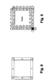
- FIG. 8 summarizes which membrane cells of organ O are respectively assigned the membrane codes CM.
- the zygote retains its code 0
- the South membrane cells have a membrane code 1
- the membrane cell of the Southeast angle has the code 2
- the East membrane cells have the code 3
- the cells West membrane cells have code 4
- the northwest corner membrane cell has code 5
- North membrane cells have code 6
- the Northeast membrane cell has code 7.
- FIG. 9 summarizes, for all the cells of the organ, what will be the status code of the cell concerned, replaced during the growth of this organ. This replacement is made according to the following table 4 (also given purely by way of illustration): TABLE 4 Membrane code ⁇ Status code> Neighbor East ⁇ Status code> Voisine Nord 0 4 4 1 4 5 2 1 4 3 1 4 4 5 4 5 4 1 6 4 1 7 6 6
- the local address calculation is initialized. This is achieved by initialization to "1" of the local address registers 9 by the Load_Zygote signal controlling the multiplexers 33 and 34 (FIG. 3).
- the address calculation is kept effective over the entire surface of the membrane by the Load_CMH signal generated by the OR gate 35 (FIG. 3B) from the Load_Membrane signal (output from the AND gate 91), from the Load_Interior signal (output from the logic gate ET 93) and of the Load_Zygote signal.
- the Load_CMH signal activates the loading element 36 to load the registers 9 storing the local address.
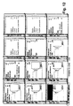
- Figures 10 to 14 illustrate the growth of organ 0 from the zygote of global address 1.1 according to the genome which has been indicated in table 1 above. In each figure, the state of the signals and codes in the cell has been represented to illustrate the state thereof.
- the zygote contains the code word No. 2, while the global address cells 1,2 and 2,1 have received the code word No. 1 in which the status code has been changed from 1 to 4 by the loading elements 21 and 22, from the memories of constants 23 and 24 (Fig. 3), of the zygote.
- the other cells are still inactive since they have not yet received any code words.
- the status code 4 now assigns, to address cells 1,2 and 2,1, the status of membrane cell.
- the cycle counter in each of the cells now marks 232.
- the first gene in the genome is placed in register 77 of the zygote.
- the decoder 78 is loaded with the local addresses of the ⁇ x and ⁇ y gene.
- the content of register 77 is then loaded into memory 79, thanks to the Load_genome signal supplied by the AND gate 98 (Fig. 3B).
- the cell cycle counters mark 290.
- the code word No. 3 is entered into the zygote. Address cells 1,3 and 3,1 have had their status code changed to ⁇ status 4>, while for address cell 2,2 this status code has been changed to ⁇ status 5>. This therefore becomes an internal cell in organ O.
- FIGS. 12, 13 and 14 show the situation respectively after 348, 406 and 464 cycles of the base clock of the processor P, FIG. 14 representing, as regards the zygote, the passage of the gene No. 5.
- organ O thus continues until the code word No. 1 reaches the extreme northeast cell of organ O.
- the SPAREY register performs the same function.
- the SPARE code merges with the local address of the last cell of organ O.
- this code can be used to reserve a certain number of cells as reserve cells capable of replacing, if necessary, defective cells.
- the AND gates 44 are then used to copy the SPARE registers to the shift register in place of the ⁇ X and ⁇ Y registers.
- the loading elements 45 and 47 are used for these operations.
- This constant of the error code allows, for example, the processor P (or any other specialized organ) to restart the loading of the organ by modifying, for example, the global address of its zygote.
- networks having a more complex hierarchy can we envisage networks comprising different bodies, each consisting of several different bodies.
Landscapes
- Physics & Mathematics (AREA)
- Engineering & Computer Science (AREA)
- Mathematical Physics (AREA)
- Biophysics (AREA)
- Computing Systems (AREA)
- General Engineering & Computer Science (AREA)
- Health & Medical Sciences (AREA)
- Life Sciences & Earth Sciences (AREA)
- Computer Hardware Design (AREA)
- Bioinformatics & Computational Biology (AREA)
- Bioinformatics & Cheminformatics (AREA)
- Evolutionary Biology (AREA)
- Theoretical Computer Science (AREA)
- Physiology (AREA)
- Molecular Biology (AREA)
- Biomedical Technology (AREA)
- Computational Linguistics (AREA)
- Data Mining & Analysis (AREA)
- Evolutionary Computation (AREA)
- General Health & Medical Sciences (AREA)
- Artificial Intelligence (AREA)
- General Physics & Mathematics (AREA)
- Software Systems (AREA)
- Genetics & Genomics (AREA)
- Management, Administration, Business Operations System, And Electronic Commerce (AREA)
- Logic Circuits (AREA)
- Micro-Organisms Or Cultivation Processes Thereof (AREA)
Applications Claiming Priority (2)
| Application Number | Priority Date | Filing Date | Title |
|---|---|---|---|
| FR9605320A FR2748168B1 (fr) | 1996-04-26 | 1996-04-26 | Systeme electronique organise en un reseau matriciel de cellules fonctionnelles |
| FR9605320 | 1996-04-26 |
Publications (2)
| Publication Number | Publication Date |
|---|---|
| EP0803982A1 true EP0803982A1 (de) | 1997-10-29 |
| EP0803982B1 EP0803982B1 (de) | 2001-01-17 |
Family
ID=9491642
Family Applications (1)
| Application Number | Title | Priority Date | Filing Date |
|---|---|---|---|
| EP97400935A Expired - Lifetime EP0803982B1 (de) | 1996-04-26 | 1997-04-24 | Elektronisches System mit einem matrixförmigen Netz aus funktionellen Zellen |
Country Status (5)
| Country | Link |
|---|---|
| US (1) | US5832469A (de) |
| EP (1) | EP0803982B1 (de) |
| JP (1) | JPH1091606A (de) |
| DE (1) | DE69703910D1 (de) |
| FR (1) | FR2748168B1 (de) |
Citations (2)
| Publication number | Priority date | Publication date | Assignee | Title |
|---|---|---|---|---|
| EP0626760A2 (de) * | 1993-05-24 | 1994-11-30 | CSEM, Centre Suisse d'Electronique et de Microtechnique S.A. | Als Zellenmatrix-Netzwerk organisiertes elektronisches System |
| WO1995017781A1 (en) * | 1993-12-23 | 1995-06-29 | The State Of Oregon, Acting By And Through The State Board Of Higher Education On Behalf Of Portland State University | Programmable analog array circuit |
-
1996
- 1996-04-26 FR FR9605320A patent/FR2748168B1/fr not_active Expired - Fee Related
-
1997
- 1997-04-21 US US08/844,729 patent/US5832469A/en not_active Expired - Fee Related
- 1997-04-24 DE DE69703910T patent/DE69703910D1/de not_active Expired - Lifetime
- 1997-04-24 EP EP97400935A patent/EP0803982B1/de not_active Expired - Lifetime
- 1997-04-28 JP JP9122902A patent/JPH1091606A/ja active Pending
Patent Citations (2)
| Publication number | Priority date | Publication date | Assignee | Title |
|---|---|---|---|---|
| EP0626760A2 (de) * | 1993-05-24 | 1994-11-30 | CSEM, Centre Suisse d'Electronique et de Microtechnique S.A. | Als Zellenmatrix-Netzwerk organisiertes elektronisches System |
| WO1995017781A1 (en) * | 1993-12-23 | 1995-06-29 | The State Of Oregon, Acting By And Through The State Board Of Higher Education On Behalf Of Portland State University | Programmable analog array circuit |
Non-Patent Citations (1)
| Title |
|---|
| MARCHAL P ET AL: "ACHIEVING VON NEUMANN'S DREAM: ARTIFICIAL LIFE ON SILICON", INTERNATIONAL CONFERENCE ON NEURAL NETWORKS/ WORLD CONGRESS ON COMPUTATIONAL INTELLIGENCE, ORLANDO, JUNE 27 - 29, 1994, vol. 4, 27 June 1994 (1994-06-27), INSTITUTE OF ELECTRICAL AND ELECTRONICS ENGINEERS, pages 2321 - 2326, XP000509809 * |
Also Published As
| Publication number | Publication date |
|---|---|
| EP0803982B1 (de) | 2001-01-17 |
| FR2748168B1 (fr) | 1998-06-12 |
| FR2748168A1 (fr) | 1997-10-31 |
| US5832469A (en) | 1998-11-03 |
| DE69703910D1 (de) | 2001-02-22 |
| JPH1091606A (ja) | 1998-04-10 |
Similar Documents
| Publication | Publication Date | Title |
|---|---|---|
| Emmert et al. | Dynamic fault tolerance in FPGAs via partial reconfiguration | |
| EP1116130B1 (de) | Gatter von parallelen prozessoren mit fehlertoleranz der prozessoren und rekonfigurierungsverfahren dafür | |
| EP0104293B1 (de) | Anordnung zum Laden und Lesen verschiedener Kippschaltungsketten in einem Datenverarbeitungssystem | |
| EP0626760B1 (de) | Als Zellenmatrix-Netzwerk organisiertes elektronisches System | |
| FR2558989A1 (fr) | Procede et dispositif d'integration de circuits au niveau d'une tranche de semi-conducteur | |
| FR2612313A1 (fr) | Selecteur programmable d'options | |
| FR2936626A1 (fr) | Dispositif de traitement en parallele d'un flux de donnees | |
| EP2940690B1 (de) | Bidirektionaler Zähler in einem Flash-Speicher | |
| EP0490738B1 (de) | Integrierter Schaltkreis mit Peripherieprüfungssteuerung | |
| EP0762285B1 (de) | Elektronisches prüfbares System | |
| EP0803982B1 (de) | Elektronisches System mit einem matrixförmigen Netz aus funktionellen Zellen | |
| EP0543698A1 (de) | Vorrichtung zur Benutzung von Fehlerinformationen eines Einzel- oder Mehrrechnersystems eines Flugzeuges | |
| EP0469507A1 (de) | Integrierte Schaltung mit einer Standardzelle, einer Anwendungszelle und einer Prüfzelle | |
| WO2013104875A1 (fr) | Systeme et procede de gestion de correspondance entre une memoire cache et une memoire principale | |
| FR2742560A1 (fr) | Architecture de systeme en tableau de processeurs a structures paralleles multiples | |
| FR2751082A1 (fr) | Dispositif de commutation notamment de systeme sous test | |
| EP3811093B1 (de) | Verfahren zur herstellung einer für strahlungsschutz optimierten schaltung | |
| EP2264610B1 (de) | Verbindungsnetz mit dynamischen Unternetzen | |
| FR2806498A1 (fr) | Systeme informatique de calcul et procede de calcul mis en oeuvre au moyen d'un tel systeme | |
| EP1493083B1 (de) | Umkonfigurierbares steuersystem auf der basis einer hardwareimplementierung von petri-graphen | |
| EP0634724A1 (de) | Verarbeitungssystem mit gemeinschaftlichem Speicher | |
| FR2660510A1 (fr) | Procede et dispositif d'interconnexion programmable entre deux ensembles de circuits electroniques et application a un circuit logique programmable. | |
| FR2632093A1 (fr) | Memoire modulaire | |
| FR3084179A1 (fr) | Acces direct en memoire | |
| FR2945393A1 (fr) | Procede de protection de circuits electroniques, dispositif et systeme mettant en oeuvre le procede |
Legal Events
| Date | Code | Title | Description |
|---|---|---|---|
| PUAI | Public reference made under article 153(3) epc to a published international application that has entered the european phase |
Free format text: ORIGINAL CODE: 0009012 |
|
| AK | Designated contracting states |
Kind code of ref document: A1 Designated state(s): CH DE FR GB LI NL |
|
| 17P | Request for examination filed |
Effective date: 19980309 |
|
| GRAG | Despatch of communication of intention to grant |
Free format text: ORIGINAL CODE: EPIDOS AGRA |
|
| RTI1 | Title (correction) |
Free format text: ELECTRONIC SYSTEM ORGANIZED IN A MATRIX ARRAY OF FUNCTIONAL CELLS |
|
| 17Q | First examination report despatched |
Effective date: 20000324 |
|
| GRAG | Despatch of communication of intention to grant |
Free format text: ORIGINAL CODE: EPIDOS AGRA |
|
| GRAG | Despatch of communication of intention to grant |
Free format text: ORIGINAL CODE: EPIDOS AGRA |
|
| GRAH | Despatch of communication of intention to grant a patent |
Free format text: ORIGINAL CODE: EPIDOS IGRA |
|
| GRAH | Despatch of communication of intention to grant a patent |
Free format text: ORIGINAL CODE: EPIDOS IGRA |
|
| GRAA | (expected) grant |
Free format text: ORIGINAL CODE: 0009210 |
|
| AK | Designated contracting states |
Kind code of ref document: B1 Designated state(s): CH DE FR GB LI NL |
|
| PG25 | Lapsed in a contracting state [announced via postgrant information from national office to epo] |
Ref country code: NL Free format text: LAPSE BECAUSE OF FAILURE TO SUBMIT A TRANSLATION OF THE DESCRIPTION OR TO PAY THE FEE WITHIN THE PRESCRIBED TIME-LIMIT Effective date: 20010117 Ref country code: GB Free format text: LAPSE BECAUSE OF FAILURE TO SUBMIT A TRANSLATION OF THE DESCRIPTION OR TO PAY THE FEE WITHIN THE PRESCRIBED TIME-LIMIT Effective date: 20010117 Ref country code: FR Free format text: THE PATENT HAS BEEN ANNULLED BY A DECISION OF A NATIONAL AUTHORITY Effective date: 20010117 |
|
| REG | Reference to a national code |
Ref country code: CH Ref legal event code: EP |
|
| REF | Corresponds to: |
Ref document number: 69703910 Country of ref document: DE Date of ref document: 20010222 |
|
| PG25 | Lapsed in a contracting state [announced via postgrant information from national office to epo] |
Ref country code: DE Free format text: LAPSE BECAUSE OF FAILURE TO SUBMIT A TRANSLATION OF THE DESCRIPTION OR TO PAY THE FEE WITHIN THE PRESCRIBED TIME-LIMIT Effective date: 20010418 |
|
| PG25 | Lapsed in a contracting state [announced via postgrant information from national office to epo] |
Ref country code: LI Free format text: LAPSE BECAUSE OF NON-PAYMENT OF DUE FEES Effective date: 20010523 Ref country code: CH Free format text: LAPSE BECAUSE OF NON-PAYMENT OF DUE FEES Effective date: 20010523 |
|
| NLV1 | Nl: lapsed or annulled due to failure to fulfill the requirements of art. 29p and 29m of the patents act | ||
| GBV | Gb: ep patent (uk) treated as always having been void in accordance with gb section 77(7)/1977 [no translation filed] |
Effective date: 20010117 |
|
| PLBE | No opposition filed within time limit |
Free format text: ORIGINAL CODE: 0009261 |
|
| STAA | Information on the status of an ep patent application or granted ep patent |
Free format text: STATUS: NO OPPOSITION FILED WITHIN TIME LIMIT |
|
| REG | Reference to a national code |
Ref country code: CH Ref legal event code: PL |
|
| 26N | No opposition filed | ||
| REG | Reference to a national code |
Ref country code: FR Ref legal event code: ST |