EP0804276B1 - Procede et appareil permettant de nettoyer l'air ambiant par contact avec un substrat fixe - Google Patents
Procede et appareil permettant de nettoyer l'air ambiant par contact avec un substrat fixe Download PDFInfo
- Publication number
- EP0804276B1 EP0804276B1 EP96905174A EP96905174A EP0804276B1 EP 0804276 B1 EP0804276 B1 EP 0804276B1 EP 96905174 A EP96905174 A EP 96905174A EP 96905174 A EP96905174 A EP 96905174A EP 0804276 B1 EP0804276 B1 EP 0804276B1
- Authority
- EP
- European Patent Office
- Prior art keywords
- air
- pollutant treating
- pollutant
- handling system
- ambient air
- Prior art date
- Legal status (The legal status is an assumption and is not a legal conclusion. Google has not performed a legal analysis and makes no representation as to the accuracy of the status listed.)
- Expired - Lifetime
Links
- 238000000034 method Methods 0.000 title claims abstract description 72
- 239000000758 substrate Substances 0.000 title claims abstract description 70
- 239000012080 ambient air Substances 0.000 title claims abstract description 52
- 238000004140 cleaning Methods 0.000 title claims description 17
- 239000003344 environmental pollutant Substances 0.000 claims abstract description 179
- 231100000719 pollutant Toxicity 0.000 claims abstract description 179
- 239000000203 mixture Substances 0.000 claims abstract description 101
- 239000012298 atmosphere Substances 0.000 claims abstract description 69
- 239000003570 air Substances 0.000 claims description 155
- 239000000463 material Substances 0.000 claims description 92
- CBENFWSGALASAD-UHFFFAOYSA-N Ozone Chemical compound [O-][O+]=O CBENFWSGALASAD-UHFFFAOYSA-N 0.000 claims description 74
- AMWRITDGCCNYAT-UHFFFAOYSA-L hydroxy(oxo)manganese;manganese Chemical compound [Mn].O[Mn]=O.O[Mn]=O AMWRITDGCCNYAT-UHFFFAOYSA-L 0.000 claims description 35
- 230000003197 catalytic effect Effects 0.000 claims description 20
- 238000012546 transfer Methods 0.000 claims description 19
- 230000003716 rejuvenation Effects 0.000 claims description 11
- 150000001450 anions Chemical class 0.000 claims description 9
- 238000001914 filtration Methods 0.000 claims description 6
- 239000000356 contaminant Substances 0.000 claims description 5
- 239000003973 paint Substances 0.000 claims 3
- 238000004378 air conditioning Methods 0.000 abstract description 10
- 239000003054 catalyst Substances 0.000 description 73
- 238000006243 chemical reaction Methods 0.000 description 47
- QTBSBXVTEAMEQO-UHFFFAOYSA-N Acetic acid Chemical compound CC(O)=O QTBSBXVTEAMEQO-UHFFFAOYSA-N 0.000 description 42
- XLYOFNOQVPJJNP-UHFFFAOYSA-N water Chemical compound O XLYOFNOQVPJJNP-UHFFFAOYSA-N 0.000 description 32
- MCMNRKCIXSYSNV-UHFFFAOYSA-N Zirconium dioxide Chemical compound O=[Zr]=O MCMNRKCIXSYSNV-UHFFFAOYSA-N 0.000 description 30
- NUJOXMJBOLGQSY-UHFFFAOYSA-N manganese dioxide Chemical compound O=[Mn]=O NUJOXMJBOLGQSY-UHFFFAOYSA-N 0.000 description 28
- 229910001868 water Inorganic materials 0.000 description 28
- 150000002430 hydrocarbons Chemical class 0.000 description 25
- GWEVSGVZZGPLCZ-UHFFFAOYSA-N Titan oxide Chemical compound O=[Ti]=O GWEVSGVZZGPLCZ-UHFFFAOYSA-N 0.000 description 24
- 239000011230 binding agent Substances 0.000 description 24
- 229930195733 hydrocarbon Natural products 0.000 description 24
- 238000010438 heat treatment Methods 0.000 description 23
- -1 C20 olefins Chemical class 0.000 description 19
- UGFAIRIUMAVXCW-UHFFFAOYSA-N Carbon monoxide Chemical compound [O+]#[C-] UGFAIRIUMAVXCW-UHFFFAOYSA-N 0.000 description 19
- 229910002091 carbon monoxide Inorganic materials 0.000 description 19
- 239000011248 coating agent Substances 0.000 description 18
- 238000000576 coating method Methods 0.000 description 18
- 230000008569 process Effects 0.000 description 18
- 239000002002 slurry Substances 0.000 description 18
- 229960000583 acetic acid Drugs 0.000 description 15
- PNEYBMLMFCGWSK-UHFFFAOYSA-N aluminium oxide Inorganic materials [O-2].[O-2].[O-2].[Al+3].[Al+3] PNEYBMLMFCGWSK-UHFFFAOYSA-N 0.000 description 15
- MWUXSHHQAYIFBG-UHFFFAOYSA-N nitrogen oxide Inorganic materials O=[N] MWUXSHHQAYIFBG-UHFFFAOYSA-N 0.000 description 15
- 239000011572 manganese Substances 0.000 description 14
- 239000000243 solution Substances 0.000 description 13
- VYPSYNLAJGMNEJ-UHFFFAOYSA-N Silicium dioxide Chemical compound O=[Si]=O VYPSYNLAJGMNEJ-UHFFFAOYSA-N 0.000 description 12
- 238000001179 sorption measurement Methods 0.000 description 12
- 238000012360 testing method Methods 0.000 description 12
- OKTJSMMVPCPJKN-UHFFFAOYSA-N Carbon Chemical compound [C] OKTJSMMVPCPJKN-UHFFFAOYSA-N 0.000 description 11
- 238000001816 cooling Methods 0.000 description 11
- 239000012286 potassium permanganate Substances 0.000 description 11
- 239000000126 substance Substances 0.000 description 11
- 238000001354 calcination Methods 0.000 description 10
- 150000001875 compounds Chemical class 0.000 description 10
- 239000007789 gas Substances 0.000 description 10
- 239000002245 particle Substances 0.000 description 10
- 229910052748 manganese Inorganic materials 0.000 description 9
- PPNAOCWZXJOHFK-UHFFFAOYSA-N manganese(2+);oxygen(2-) Chemical class [O-2].[Mn+2] PPNAOCWZXJOHFK-UHFFFAOYSA-N 0.000 description 9
- 229920000642 polymer Polymers 0.000 description 9
- PWHULOQIROXLJO-UHFFFAOYSA-N Manganese Chemical compound [Mn] PWHULOQIROXLJO-UHFFFAOYSA-N 0.000 description 8
- QVGXLLKOCUKJST-UHFFFAOYSA-N atomic oxygen Chemical compound [O] QVGXLLKOCUKJST-UHFFFAOYSA-N 0.000 description 8
- 239000001301 oxygen Substances 0.000 description 8
- 229910052760 oxygen Inorganic materials 0.000 description 8
- 229910009112 xH2O Inorganic materials 0.000 description 8
- 230000002378 acidificating effect Effects 0.000 description 7
- 230000006378 damage Effects 0.000 description 7
- SQQMAOCOWKFBNP-UHFFFAOYSA-L manganese(II) sulfate Chemical compound [Mn+2].[O-]S([O-])(=O)=O SQQMAOCOWKFBNP-UHFFFAOYSA-L 0.000 description 7
- 239000003921 oil Substances 0.000 description 7
- 238000005406 washing Methods 0.000 description 7
- CURLTUGMZLYLDI-UHFFFAOYSA-N Carbon dioxide Chemical compound O=C=O CURLTUGMZLYLDI-UHFFFAOYSA-N 0.000 description 6
- 229910000357 manganese(II) sulfate Inorganic materials 0.000 description 6
- 239000000377 silicon dioxide Substances 0.000 description 6
- AKEJUJNQAAGONA-UHFFFAOYSA-N sulfur trioxide Chemical compound O=S(=O)=O AKEJUJNQAAGONA-UHFFFAOYSA-N 0.000 description 6
- 239000010457 zeolite Substances 0.000 description 6
- GOPYZMJAIPBUGX-UHFFFAOYSA-N [O-2].[O-2].[Mn+4] Chemical class [O-2].[O-2].[Mn+4] GOPYZMJAIPBUGX-UHFFFAOYSA-N 0.000 description 5
- 239000003463 adsorbent Substances 0.000 description 5
- 229910052782 aluminium Inorganic materials 0.000 description 5
- XAGFODPZIPBFFR-UHFFFAOYSA-N aluminium Chemical compound [Al] XAGFODPZIPBFFR-UHFFFAOYSA-N 0.000 description 5
- 230000008901 benefit Effects 0.000 description 5
- 238000006555 catalytic reaction Methods 0.000 description 5
- 150000002696 manganese Chemical class 0.000 description 5
- 229910052751 metal Inorganic materials 0.000 description 5
- 239000002184 metal Substances 0.000 description 5
- 239000007787 solid Substances 0.000 description 5
- 229920002554 vinyl polymer Polymers 0.000 description 5
- 150000003755 zirconium compounds Chemical class 0.000 description 5
- IJGRMHOSHXDMSA-UHFFFAOYSA-N Atomic nitrogen Chemical compound N#N IJGRMHOSHXDMSA-UHFFFAOYSA-N 0.000 description 4
- 239000004215 Carbon black (E152) Substances 0.000 description 4
- RAHZWNYVWXNFOC-UHFFFAOYSA-N Sulphur dioxide Chemical compound O=S=O RAHZWNYVWXNFOC-UHFFFAOYSA-N 0.000 description 4
- 238000002441 X-ray diffraction Methods 0.000 description 4
- 239000011149 active material Substances 0.000 description 4
- 150000001449 anionic compounds Chemical class 0.000 description 4
- BRPQOXSCLDDYGP-UHFFFAOYSA-N calcium oxide Chemical compound [O-2].[Ca+2] BRPQOXSCLDDYGP-UHFFFAOYSA-N 0.000 description 4
- 239000000292 calcium oxide Substances 0.000 description 4
- ODINCKMPIJJUCX-UHFFFAOYSA-N calcium oxide Inorganic materials [Ca]=O ODINCKMPIJJUCX-UHFFFAOYSA-N 0.000 description 4
- 229910052799 carbon Inorganic materials 0.000 description 4
- 229920001577 copolymer Polymers 0.000 description 4
- 239000013078 crystal Substances 0.000 description 4
- 239000000428 dust Substances 0.000 description 4
- 238000002329 infrared spectrum Methods 0.000 description 4
- 229910001412 inorganic anion Inorganic materials 0.000 description 4
- 238000002156 mixing Methods 0.000 description 4
- 230000003647 oxidation Effects 0.000 description 4
- 238000007254 oxidation reaction Methods 0.000 description 4
- LYTNHSCLZRMKON-UHFFFAOYSA-L oxygen(2-);zirconium(4+);diacetate Chemical compound [O-2].[Zr+4].CC([O-])=O.CC([O-])=O LYTNHSCLZRMKON-UHFFFAOYSA-L 0.000 description 4
- 239000013618 particulate matter Substances 0.000 description 4
- 230000009467 reduction Effects 0.000 description 4
- 239000012266 salt solution Substances 0.000 description 4
- 229910052726 zirconium Inorganic materials 0.000 description 4
- 229910003144 α-MnO2 Inorganic materials 0.000 description 4
- QPLDLSVMHZLSFG-UHFFFAOYSA-N Copper oxide Chemical class [Cu]=O QPLDLSVMHZLSFG-UHFFFAOYSA-N 0.000 description 3
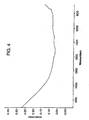
- 238000004566 IR spectroscopy Methods 0.000 description 3
- 229910018388 Mn(CH3CO2)2 Inorganic materials 0.000 description 3
- XTXRWKRVRITETP-UHFFFAOYSA-N Vinyl acetate Chemical compound CC(=O)OC=C XTXRWKRVRITETP-UHFFFAOYSA-N 0.000 description 3
- QCWXUUIWCKQGHC-UHFFFAOYSA-N Zirconium Chemical compound [Zr] QCWXUUIWCKQGHC-UHFFFAOYSA-N 0.000 description 3
- 239000007864 aqueous solution Substances 0.000 description 3
- 230000015572 biosynthetic process Effects 0.000 description 3
- 239000001569 carbon dioxide Substances 0.000 description 3
- 229910002092 carbon dioxide Inorganic materials 0.000 description 3
- 230000008859 change Effects 0.000 description 3
- 238000000354 decomposition reaction Methods 0.000 description 3
- 239000012530 fluid Substances 0.000 description 3
- 239000012362 glacial acetic acid Substances 0.000 description 3
- 238000001027 hydrothermal synthesis Methods 0.000 description 3
- 150000004679 hydroxides Chemical class 0.000 description 3
- MIVBAHRSNUNMPP-UHFFFAOYSA-N manganese(II) nitrate Inorganic materials [Mn+2].[O-][N+]([O-])=O.[O-][N+]([O-])=O MIVBAHRSNUNMPP-UHFFFAOYSA-N 0.000 description 3
- GEYXPJBPASPPLI-UHFFFAOYSA-N manganese(III) oxide Inorganic materials O=[Mn]O[Mn]=O GEYXPJBPASPPLI-UHFFFAOYSA-N 0.000 description 3
- 239000003208 petroleum Substances 0.000 description 3
- 229920000058 polyacrylate Polymers 0.000 description 3
- 239000011148 porous material Substances 0.000 description 3
- 238000000634 powder X-ray diffraction Methods 0.000 description 3
- 230000004044 response Effects 0.000 description 3
- 229920001187 thermosetting polymer Polymers 0.000 description 3
- 229930195735 unsaturated hydrocarbon Natural products 0.000 description 3
- 241000894006 Bacteria Species 0.000 description 2
- 229910021380 Manganese Chloride Inorganic materials 0.000 description 2
- GLFNIEUTAYBVOC-UHFFFAOYSA-L Manganese chloride Chemical compound Cl[Mn]Cl GLFNIEUTAYBVOC-UHFFFAOYSA-L 0.000 description 2
- GQPLMRYTRLFLPF-UHFFFAOYSA-N Nitrous Oxide Chemical compound [O-][N+]#N GQPLMRYTRLFLPF-UHFFFAOYSA-N 0.000 description 2
- 239000004952 Polyamide Substances 0.000 description 2
- 239000005062 Polybutadiene Substances 0.000 description 2
- 229920002472 Starch Polymers 0.000 description 2
- QAOWNCQODCNURD-UHFFFAOYSA-L Sulfate Chemical compound [O-]S([O-])(=O)=O QAOWNCQODCNURD-UHFFFAOYSA-L 0.000 description 2
- 229910021536 Zeolite Inorganic materials 0.000 description 2
- 239000002253 acid Substances 0.000 description 2
- 229920006397 acrylic thermoplastic Polymers 0.000 description 2
- 239000000654 additive Substances 0.000 description 2
- 150000001336 alkenes Chemical class 0.000 description 2
- 238000004458 analytical method Methods 0.000 description 2
- 238000013459 approach Methods 0.000 description 2
- 239000004221 calcium diglutamate Substances 0.000 description 2
- OSGAYBCDTDRGGQ-UHFFFAOYSA-L calcium sulfate Chemical compound [Ca+2].[O-]S([O-])(=O)=O OSGAYBCDTDRGGQ-UHFFFAOYSA-L 0.000 description 2
- 239000000969 carrier Substances 0.000 description 2
- 229910000422 cerium(IV) oxide Inorganic materials 0.000 description 2
- 239000004927 clay Substances 0.000 description 2
- 238000010276 construction Methods 0.000 description 2
- 239000008367 deionised water Substances 0.000 description 2
- 229910021641 deionized water Inorganic materials 0.000 description 2
- 238000007865 diluting Methods 0.000 description 2
- HNPSIPDUKPIQMN-UHFFFAOYSA-N dioxosilane;oxo(oxoalumanyloxy)alumane Chemical compound O=[Si]=O.O=[Al]O[Al]=O HNPSIPDUKPIQMN-UHFFFAOYSA-N 0.000 description 2
- 230000005684 electric field Effects 0.000 description 2
- 239000000839 emulsion Substances 0.000 description 2
- 239000000706 filtrate Substances 0.000 description 2
- 239000011521 glass Substances 0.000 description 2
- 239000004816 latex Substances 0.000 description 2
- 229920000126 latex Polymers 0.000 description 2
- 229940071125 manganese acetate Drugs 0.000 description 2
- 239000011565 manganese chloride Substances 0.000 description 2
- UOGMEBQRZBEZQT-UHFFFAOYSA-L manganese(2+);diacetate Chemical compound [Mn+2].CC([O-])=O.CC([O-])=O UOGMEBQRZBEZQT-UHFFFAOYSA-L 0.000 description 2
- WPBNNNQJVZRUHP-UHFFFAOYSA-L manganese(2+);methyl n-[[2-(methoxycarbonylcarbamothioylamino)phenyl]carbamothioyl]carbamate;n-[2-(sulfidocarbothioylamino)ethyl]carbamodithioate Chemical compound [Mn+2].[S-]C(=S)NCCNC([S-])=S.COC(=O)NC(=S)NC1=CC=CC=C1NC(=S)NC(=O)OC WPBNNNQJVZRUHP-UHFFFAOYSA-L 0.000 description 2
- 238000004519 manufacturing process Methods 0.000 description 2
- 239000011159 matrix material Substances 0.000 description 2
- 229910044991 metal oxide Inorganic materials 0.000 description 2
- 150000004706 metal oxides Chemical class 0.000 description 2
- 150000005673 monoalkenes Chemical class 0.000 description 2
- 150000002823 nitrates Chemical class 0.000 description 2
- 229910052757 nitrogen Inorganic materials 0.000 description 2
- RVTZCBVAJQQJTK-UHFFFAOYSA-N oxygen(2-);zirconium(4+) Chemical compound [O-2].[O-2].[Zr+4] RVTZCBVAJQQJTK-UHFFFAOYSA-N 0.000 description 2
- BASFCYQUMIYNBI-UHFFFAOYSA-N platinum Chemical compound [Pt] BASFCYQUMIYNBI-UHFFFAOYSA-N 0.000 description 2
- 229920001200 poly(ethylene-vinyl acetate) Polymers 0.000 description 2
- 229920003229 poly(methyl methacrylate) Polymers 0.000 description 2
- 229920002647 polyamide Polymers 0.000 description 2
- 229920002857 polybutadiene Polymers 0.000 description 2
- 229920000728 polyester Polymers 0.000 description 2
- 239000000843 powder Substances 0.000 description 2
- 239000002243 precursor Substances 0.000 description 2
- 239000000047 product Substances 0.000 description 2
- 239000003870 refractory metal Substances 0.000 description 2
- 238000012552 review Methods 0.000 description 2
- 239000003381 stabilizer Substances 0.000 description 2
- 239000008107 starch Substances 0.000 description 2
- 235000019698 starch Nutrition 0.000 description 2
- 238000003756 stirring Methods 0.000 description 2
- 150000003467 sulfuric acid derivatives Chemical class 0.000 description 2
- 230000000153 supplemental effect Effects 0.000 description 2
- 238000003786 synthesis reaction Methods 0.000 description 2
- 229920001169 thermoplastic Polymers 0.000 description 2
- 239000004416 thermosoftening plastic Substances 0.000 description 2
- 238000011144 upstream manufacturing Methods 0.000 description 2
- 238000009423 ventilation Methods 0.000 description 2
- 125000000391 vinyl group Chemical group [H]C([*])=C([H])[H] 0.000 description 2
- 229910001928 zirconium oxide Inorganic materials 0.000 description 2
- CHJAYYWUZLWNSQ-UHFFFAOYSA-N 1-chloro-1,2,2-trifluoroethene;ethene Chemical group C=C.FC(F)=C(F)Cl CHJAYYWUZLWNSQ-UHFFFAOYSA-N 0.000 description 1
- JYLNVJYYQQXNEK-UHFFFAOYSA-N 3-amino-2-(4-chlorophenyl)-1-propanesulfonic acid Chemical compound OS(=O)(=O)CC(CN)C1=CC=C(Cl)C=C1 JYLNVJYYQQXNEK-UHFFFAOYSA-N 0.000 description 1
- DUFCMRCMPHIFTR-UHFFFAOYSA-N 5-(dimethylsulfamoyl)-2-methylfuran-3-carboxylic acid Chemical compound CN(C)S(=O)(=O)C1=CC(C(O)=O)=C(C)O1 DUFCMRCMPHIFTR-UHFFFAOYSA-N 0.000 description 1
- RZVAJINKPMORJF-UHFFFAOYSA-N Acetaminophen Chemical compound CC(=O)NC1=CC=C(O)C=C1 RZVAJINKPMORJF-UHFFFAOYSA-N 0.000 description 1
- VHUUQVKOLVNVRT-UHFFFAOYSA-N Ammonium hydroxide Chemical compound [NH4+].[OH-] VHUUQVKOLVNVRT-UHFFFAOYSA-N 0.000 description 1
- 238000004438 BET method Methods 0.000 description 1
- BVKZGUZCCUSVTD-UHFFFAOYSA-L Carbonate Chemical compound [O-]C([O-])=O BVKZGUZCCUSVTD-UHFFFAOYSA-L 0.000 description 1
- RWSOTUBLDIXVET-UHFFFAOYSA-N Dihydrogen sulfide Chemical compound S RWSOTUBLDIXVET-UHFFFAOYSA-N 0.000 description 1
- MYMOFIZGZYHOMD-UHFFFAOYSA-N Dioxygen Chemical compound O=O MYMOFIZGZYHOMD-UHFFFAOYSA-N 0.000 description 1
- 229920001780 ECTFE Polymers 0.000 description 1
- 229920002943 EPDM rubber Polymers 0.000 description 1
- 239000005977 Ethylene Substances 0.000 description 1
- DGAQECJNVWCQMB-PUAWFVPOSA-M Ilexoside XXIX Chemical compound C[C@@H]1CC[C@@]2(CC[C@@]3(C(=CC[C@H]4[C@]3(CC[C@@H]5[C@@]4(CC[C@@H](C5(C)C)OS(=O)(=O)[O-])C)C)[C@@H]2[C@]1(C)O)C)C(=O)O[C@H]6[C@@H]([C@H]([C@@H]([C@H](O6)CO)O)O)O.[Na+] DGAQECJNVWCQMB-PUAWFVPOSA-M 0.000 description 1
- 229910002651 NO3 Inorganic materials 0.000 description 1
- 229920000459 Nitrile rubber Polymers 0.000 description 1
- 239000002033 PVDF binder Substances 0.000 description 1
- 239000004698 Polyethylene Substances 0.000 description 1
- 239000004642 Polyimide Substances 0.000 description 1
- 239000004743 Polypropylene Substances 0.000 description 1
- 239000004793 Polystyrene Substances 0.000 description 1
- 239000004372 Polyvinyl alcohol Substances 0.000 description 1
- RTAQQCXQSZGOHL-UHFFFAOYSA-N Titanium Chemical compound [Ti] RTAQQCXQSZGOHL-UHFFFAOYSA-N 0.000 description 1
- 150000001242 acetic acid derivatives Chemical class 0.000 description 1
- NIXOWILDQLNWCW-UHFFFAOYSA-N acrylic acid group Chemical group C(C=C)(=O)O NIXOWILDQLNWCW-UHFFFAOYSA-N 0.000 description 1
- 229920006243 acrylic copolymer Polymers 0.000 description 1
- 238000003915 air pollution Methods 0.000 description 1
- 150000001298 alcohols Chemical class 0.000 description 1
- 150000001299 aldehydes Chemical class 0.000 description 1
- 229910000287 alkaline earth metal oxide Inorganic materials 0.000 description 1
- 230000004075 alteration Effects 0.000 description 1
- 239000000908 ammonium hydroxide Substances 0.000 description 1
- 244000052616 bacterial pathogen Species 0.000 description 1
- 229910052788 barium Inorganic materials 0.000 description 1
- DSAJWYNOEDNPEQ-UHFFFAOYSA-N barium atom Chemical compound [Ba] DSAJWYNOEDNPEQ-UHFFFAOYSA-N 0.000 description 1
- 230000005540 biological transmission Effects 0.000 description 1
- 238000007664 blowing Methods 0.000 description 1
- 230000001680 brushing effect Effects 0.000 description 1
- 125000005587 carbonate group Chemical group 0.000 description 1
- 150000007942 carboxylates Chemical class 0.000 description 1
- 150000001732 carboxylic acid derivatives Chemical class 0.000 description 1
- 239000000919 ceramic Substances 0.000 description 1
- CETPSERCERDGAM-UHFFFAOYSA-N ceric oxide Chemical compound O=[Ce]=O CETPSERCERDGAM-UHFFFAOYSA-N 0.000 description 1
- 238000001311 chemical methods and process Methods 0.000 description 1
- 150000001805 chlorine compounds Chemical class 0.000 description 1
- 125000001309 chloro group Chemical group Cl* 0.000 description 1
- 238000002485 combustion reaction Methods 0.000 description 1
- 239000002826 coolant Substances 0.000 description 1
- 230000003247 decreasing effect Effects 0.000 description 1
- 230000001419 dependent effect Effects 0.000 description 1
- 239000002274 desiccant Substances 0.000 description 1
- 238000013461 design Methods 0.000 description 1
- 238000003795 desorption Methods 0.000 description 1
- 238000001514 detection method Methods 0.000 description 1
- 230000001627 detrimental effect Effects 0.000 description 1
- RJYMRRJVDRJMJW-UHFFFAOYSA-L dibromomanganese Chemical compound Br[Mn]Br RJYMRRJVDRJMJW-UHFFFAOYSA-L 0.000 description 1
- QDOXWKRWXJOMAK-UHFFFAOYSA-N dichromium trioxide Chemical compound O=[Cr]O[Cr]=O QDOXWKRWXJOMAK-UHFFFAOYSA-N 0.000 description 1
- 238000005906 dihydroxylation reaction Methods 0.000 description 1
- 229910001882 dioxygen Inorganic materials 0.000 description 1
- 238000007598 dipping method Methods 0.000 description 1
- 230000008034 disappearance Effects 0.000 description 1
- 239000006185 dispersion Substances 0.000 description 1
- 238000001035 drying Methods 0.000 description 1
- 229920001971 elastomer Polymers 0.000 description 1
- 239000012717 electrostatic precipitator Substances 0.000 description 1
- 239000003822 epoxy resin Substances 0.000 description 1
- 150000002148 esters Chemical class 0.000 description 1
- 150000002170 ethers Chemical class 0.000 description 1
- 239000005038 ethylene vinyl acetate Substances 0.000 description 1
- 239000012065 filter cake Substances 0.000 description 1
- NBVXSUQYWXRMNV-UHFFFAOYSA-N fluoromethane Chemical compound FC NBVXSUQYWXRMNV-UHFFFAOYSA-N 0.000 description 1
- 229920002313 fluoropolymer Polymers 0.000 description 1
- 239000011491 glass wool Substances 0.000 description 1
- LNEPOXFFQSENCJ-UHFFFAOYSA-N haloperidol Chemical compound C1CC(O)(C=2C=CC(Cl)=CC=2)CCN1CCCC(=O)C1=CC=C(F)C=C1 LNEPOXFFQSENCJ-UHFFFAOYSA-N 0.000 description 1
- 230000017525 heat dissipation Effects 0.000 description 1
- 229910000037 hydrogen sulfide Inorganic materials 0.000 description 1
- 125000002887 hydroxy group Chemical group [H]O* 0.000 description 1
- 238000011065 in-situ storage Methods 0.000 description 1
- 150000002576 ketones Chemical class 0.000 description 1
- JCCNYMKQOSZNPW-UHFFFAOYSA-N loratadine Chemical compound C1CN(C(=O)OCC)CCC1=C1C2=NC=CC=C2CCC2=CC(Cl)=CC=C21 JCCNYMKQOSZNPW-UHFFFAOYSA-N 0.000 description 1
- 235000002867 manganese chloride Nutrition 0.000 description 1
- 150000002697 manganese compounds Chemical class 0.000 description 1
- CESXSDZNZGSWSP-UHFFFAOYSA-L manganese(2+);diacetate;tetrahydrate Chemical compound O.O.O.O.[Mn+2].CC([O-])=O.CC([O-])=O CESXSDZNZGSWSP-UHFFFAOYSA-L 0.000 description 1
- 238000005259 measurement Methods 0.000 description 1
- QSHDDOUJBYECFT-UHFFFAOYSA-N mercury Chemical compound [Hg] QSHDDOUJBYECFT-UHFFFAOYSA-N 0.000 description 1
- 229910052753 mercury Inorganic materials 0.000 description 1
- 229910021645 metal ion Inorganic materials 0.000 description 1
- 239000002808 molecular sieve Substances 0.000 description 1
- NHNBFGGVMKEFGY-UHFFFAOYSA-N nitrate group Chemical group [N+](=O)([O-])[O-] NHNBFGGVMKEFGY-UHFFFAOYSA-N 0.000 description 1
- UJVRJBAUJYZFIX-UHFFFAOYSA-N nitric acid;oxozirconium Chemical compound [Zr]=O.O[N+]([O-])=O.O[N+]([O-])=O UJVRJBAUJYZFIX-UHFFFAOYSA-N 0.000 description 1
- 239000001272 nitrous oxide Substances 0.000 description 1
- 230000001473 noxious effect Effects 0.000 description 1
- TWNQGVIAIRXVLR-UHFFFAOYSA-N oxo(oxoalumanyloxy)alumane Chemical compound O=[Al]O[Al]=O TWNQGVIAIRXVLR-UHFFFAOYSA-N 0.000 description 1
- 230000000737 periodic effect Effects 0.000 description 1
- 239000012169 petroleum derived wax Substances 0.000 description 1
- 235000019381 petroleum wax Nutrition 0.000 description 1
- 229920001568 phenolic resin Polymers 0.000 description 1
- 239000005011 phenolic resin Substances 0.000 description 1
- 229920003023 plastic Polymers 0.000 description 1
- 239000004033 plastic Substances 0.000 description 1
- 229910052697 platinum Inorganic materials 0.000 description 1
- 229920001084 poly(chloroprene) Polymers 0.000 description 1
- 229920002239 polyacrylonitrile Polymers 0.000 description 1
- 229920000647 polyepoxide Polymers 0.000 description 1
- 229920000573 polyethylene Polymers 0.000 description 1
- 229920001721 polyimide Polymers 0.000 description 1
- 229920001195 polyisoprene Polymers 0.000 description 1
- 229920000193 polymethacrylate Polymers 0.000 description 1
- 229920000098 polyolefin Polymers 0.000 description 1
- 229920006380 polyphenylene oxide Polymers 0.000 description 1
- 229920000069 polyphenylene sulfide Polymers 0.000 description 1
- 229920001155 polypropylene Polymers 0.000 description 1
- 229920002223 polystyrene Polymers 0.000 description 1
- 229920001343 polytetrafluoroethylene Polymers 0.000 description 1
- 229920002635 polyurethane Polymers 0.000 description 1
- 239000004814 polyurethane Substances 0.000 description 1
- 229920002451 polyvinyl alcohol Polymers 0.000 description 1
- 229940068984 polyvinyl alcohol Drugs 0.000 description 1
- 235000019422 polyvinyl alcohol Nutrition 0.000 description 1
- 229920002620 polyvinyl fluoride Polymers 0.000 description 1
- 229920002981 polyvinylidene fluoride Polymers 0.000 description 1
- 239000002244 precipitate Substances 0.000 description 1
- 239000012716 precipitator Substances 0.000 description 1
- QQONPFPTGQHPMA-UHFFFAOYSA-N propylene Natural products CC=C QQONPFPTGQHPMA-UHFFFAOYSA-N 0.000 description 1
- 125000004805 propylene group Chemical group [H]C([H])([H])C([H])([*:1])C([H])([H])[*:2] 0.000 description 1
- 230000001681 protective effect Effects 0.000 description 1
- 238000005086 pumping Methods 0.000 description 1
- 239000005297 pyrex Substances 0.000 description 1
- 230000005855 radiation Effects 0.000 description 1
- 238000009877 rendering Methods 0.000 description 1
- 239000005060 rubber Substances 0.000 description 1
- 150000003839 salts Chemical class 0.000 description 1
- 150000004760 silicates Chemical class 0.000 description 1
- RMAQACBXLXPBSY-UHFFFAOYSA-N silicic acid Chemical compound O[Si](O)(O)O RMAQACBXLXPBSY-UHFFFAOYSA-N 0.000 description 1
- 229920005573 silicon-containing polymer Polymers 0.000 description 1
- 239000011734 sodium Substances 0.000 description 1
- 229910052708 sodium Inorganic materials 0.000 description 1
- URGAHOPLAPQHLN-UHFFFAOYSA-N sodium aluminosilicate Chemical compound [Na+].[Al+3].[O-][Si]([O-])=O.[O-][Si]([O-])=O URGAHOPLAPQHLN-UHFFFAOYSA-N 0.000 description 1
- 239000004071 soot Substances 0.000 description 1
- 238000001228 spectrum Methods 0.000 description 1
- 239000007921 spray Substances 0.000 description 1
- 238000005507 spraying Methods 0.000 description 1
- 238000003860 storage Methods 0.000 description 1
- 229920001909 styrene-acrylic polymer Polymers 0.000 description 1
- XTQHKBHJIVJGKJ-UHFFFAOYSA-N sulfur monoxide Chemical class S=O XTQHKBHJIVJGKJ-UHFFFAOYSA-N 0.000 description 1
- 229910052815 sulfur oxide Inorganic materials 0.000 description 1
- 239000011269 tar Substances 0.000 description 1
- 239000011270 tar paper Substances 0.000 description 1
- ISXSCDLOGDJUNJ-UHFFFAOYSA-N tert-butyl prop-2-enoate Chemical compound CC(C)(C)OC(=O)C=C ISXSCDLOGDJUNJ-UHFFFAOYSA-N 0.000 description 1
- 125000000383 tetramethylene group Chemical group [H]C([H])([*:1])C([H])([H])C([H])([H])C([H])([H])[*:2] 0.000 description 1
- 238000007669 thermal treatment Methods 0.000 description 1
- 239000010936 titanium Substances 0.000 description 1
- 229910052719 titanium Inorganic materials 0.000 description 1
- CENHPXAQKISCGD-UHFFFAOYSA-N trioxathietane 4,4-dioxide Chemical compound O=S1(=O)OOO1 CENHPXAQKISCGD-UHFFFAOYSA-N 0.000 description 1
- 229910052720 vanadium Inorganic materials 0.000 description 1
- GPPXJZIENCGNKB-UHFFFAOYSA-N vanadium Chemical compound [V]#[V] GPPXJZIENCGNKB-UHFFFAOYSA-N 0.000 description 1
- 229920001567 vinyl ester resin Polymers 0.000 description 1
- 239000002912 waste gas Substances 0.000 description 1
Images


Classifications
-
- B—PERFORMING OPERATIONS; TRANSPORTING
- B01—PHYSICAL OR CHEMICAL PROCESSES OR APPARATUS IN GENERAL
- B01D—SEPARATION
- B01D46/00—Filters or filtering processes specially modified for separating dispersed particles from gases or vapours
- B01D46/0052—Filters or filtering processes specially modified for separating dispersed particles from gases or vapours with filtering elements moving during filtering operation
-
- B—PERFORMING OPERATIONS; TRANSPORTING
- B01—PHYSICAL OR CHEMICAL PROCESSES OR APPARATUS IN GENERAL
- B01D—SEPARATION
- B01D53/00—Separation of gases or vapours; Recovering vapours of volatile solvents from gases; Chemical or biological purification of waste gases, e.g. engine exhaust gases, smoke, fumes, flue gases, aerosols
- B01D53/34—Chemical or biological purification of waste gases
- B01D53/74—General processes for purification of waste gases; Apparatus or devices specially adapted therefor
- B01D53/86—Catalytic processes
- B01D53/88—Handling or mounting catalysts
-
- B—PERFORMING OPERATIONS; TRANSPORTING
- B01—PHYSICAL OR CHEMICAL PROCESSES OR APPARATUS IN GENERAL
- B01D—SEPARATION
- B01D53/00—Separation of gases or vapours; Recovering vapours of volatile solvents from gases; Chemical or biological purification of waste gases, e.g. engine exhaust gases, smoke, fumes, flue gases, aerosols
- B01D53/02—Separation of gases or vapours; Recovering vapours of volatile solvents from gases; Chemical or biological purification of waste gases, e.g. engine exhaust gases, smoke, fumes, flue gases, aerosols by adsorption, e.g. preparative gas chromatography
- B01D53/04—Separation of gases or vapours; Recovering vapours of volatile solvents from gases; Chemical or biological purification of waste gases, e.g. engine exhaust gases, smoke, fumes, flue gases, aerosols by adsorption, e.g. preparative gas chromatography with stationary adsorbents
- B01D53/0407—Constructional details of adsorbing systems
- B01D53/0415—Beds in cartridges
-
- B—PERFORMING OPERATIONS; TRANSPORTING
- B01—PHYSICAL OR CHEMICAL PROCESSES OR APPARATUS IN GENERAL
- B01D—SEPARATION
- B01D53/00—Separation of gases or vapours; Recovering vapours of volatile solvents from gases; Chemical or biological purification of waste gases, e.g. engine exhaust gases, smoke, fumes, flue gases, aerosols
- B01D53/34—Chemical or biological purification of waste gases
- B01D53/74—General processes for purification of waste gases; Apparatus or devices specially adapted therefor
- B01D53/86—Catalytic processes
- B01D53/8671—Removing components of defined structure not provided for in B01D53/8603 - B01D53/8668
- B01D53/8675—Ozone
-
- B—PERFORMING OPERATIONS; TRANSPORTING
- B01—PHYSICAL OR CHEMICAL PROCESSES OR APPARATUS IN GENERAL
- B01D—SEPARATION
- B01D53/00—Separation of gases or vapours; Recovering vapours of volatile solvents from gases; Chemical or biological purification of waste gases, e.g. engine exhaust gases, smoke, fumes, flue gases, aerosols
- B01D53/34—Chemical or biological purification of waste gases
- B01D53/74—General processes for purification of waste gases; Apparatus or devices specially adapted therefor
- B01D53/86—Catalytic processes
- B01D53/88—Handling or mounting catalysts
- B01D53/885—Devices in general for catalytic purification of waste gases
-
- B—PERFORMING OPERATIONS; TRANSPORTING
- B01—PHYSICAL OR CHEMICAL PROCESSES OR APPARATUS IN GENERAL
- B01D—SEPARATION
- B01D2253/00—Adsorbents used in seperation treatment of gases and vapours
- B01D2253/10—Inorganic adsorbents
- B01D2253/102—Carbon
-
- B—PERFORMING OPERATIONS; TRANSPORTING
- B01—PHYSICAL OR CHEMICAL PROCESSES OR APPARATUS IN GENERAL
- B01D—SEPARATION
- B01D2253/00—Adsorbents used in seperation treatment of gases and vapours
- B01D2253/10—Inorganic adsorbents
- B01D2253/106—Silica or silicates
- B01D2253/108—Zeolites
-
- B—PERFORMING OPERATIONS; TRANSPORTING
- B01—PHYSICAL OR CHEMICAL PROCESSES OR APPARATUS IN GENERAL
- B01D—SEPARATION
- B01D2253/00—Adsorbents used in seperation treatment of gases and vapours
- B01D2253/10—Inorganic adsorbents
- B01D2253/112—Metals or metal compounds not provided for in B01D2253/104 or B01D2253/106
-
- B—PERFORMING OPERATIONS; TRANSPORTING
- B01—PHYSICAL OR CHEMICAL PROCESSES OR APPARATUS IN GENERAL
- B01D—SEPARATION
- B01D2253/00—Adsorbents used in seperation treatment of gases and vapours
- B01D2253/25—Coated, impregnated or composite adsorbents
-
- B—PERFORMING OPERATIONS; TRANSPORTING
- B01—PHYSICAL OR CHEMICAL PROCESSES OR APPARATUS IN GENERAL
- B01D—SEPARATION
- B01D2253/00—Adsorbents used in seperation treatment of gases and vapours
- B01D2253/30—Physical properties of adsorbents
- B01D2253/34—Specific shapes
- B01D2253/342—Monoliths
-
- B—PERFORMING OPERATIONS; TRANSPORTING
- B01—PHYSICAL OR CHEMICAL PROCESSES OR APPARATUS IN GENERAL
- B01D—SEPARATION
- B01D2257/00—Components to be removed
- B01D2257/10—Single element gases other than halogens
- B01D2257/106—Ozone
-
- B—PERFORMING OPERATIONS; TRANSPORTING
- B01—PHYSICAL OR CHEMICAL PROCESSES OR APPARATUS IN GENERAL
- B01D—SEPARATION
- B01D2257/00—Components to be removed
- B01D2257/50—Carbon oxides
- B01D2257/502—Carbon monoxide
-
- B—PERFORMING OPERATIONS; TRANSPORTING
- B01—PHYSICAL OR CHEMICAL PROCESSES OR APPARATUS IN GENERAL
- B01D—SEPARATION
- B01D2257/00—Components to be removed
- B01D2257/70—Organic compounds not provided for in groups B01D2257/00 - B01D2257/602
- B01D2257/702—Hydrocarbons
-
- B—PERFORMING OPERATIONS; TRANSPORTING
- B01—PHYSICAL OR CHEMICAL PROCESSES OR APPARATUS IN GENERAL
- B01D—SEPARATION
- B01D2259/00—Type of treatment
- B01D2259/45—Gas separation or purification devices adapted for specific applications
- B01D2259/455—Gas separation or purification devices adapted for specific applications for transportable use
- B01D2259/4558—Gas separation or purification devices adapted for specific applications for transportable use for being employed as mobile cleaners for ambient air, i.e. the earth's atmosphere
-
- B—PERFORMING OPERATIONS; TRANSPORTING
- B01—PHYSICAL OR CHEMICAL PROCESSES OR APPARATUS IN GENERAL
- B01D—SEPARATION
- B01D2279/00—Filters adapted for separating dispersed particles from gases or vapours specially modified for specific uses
- B01D2279/40—Filters adapted for separating dispersed particles from gases or vapours specially modified for specific uses for cleaning of environmental air, e.g. by filters installed on vehicles or on streets
Definitions
- the present invention relates to a method and apparatus for cleaning the atmosphere; and more particularly to a stationary substrate comprising at least one atmosphere contacting surface having a pollutant treating material thereon.
- U.S. Patent No. 3,738,088 discloses an air filtering assembly for cleaning pollution from the ambient air by utilizing a vehicle as a mobile cleaning device.
- a variety of elements are used in combination with a vehicle to clean the ambient air as the vehicle is driven through the environment.
- modified vehicles include ducting to control air stream velocity and direct the air to a variety of filters, electronic precipitators and catalyzed postfilters.
- German Patent DE 43 18 738 C1 also discloses a process for the physical and chemical cleaning of outside air.
- Motor vehicles are used as carriers of conventional filters and/or catalysts, which do not constitute operational components of the vehicle but are used to directly clean atmospheric air.
- German patent DE 40 07 965 C2 to Klaus Hager discloses a catalyst comprising copper oxides for converting ozone and a mixture of copper oxides and manganese oxides for converting carbon monoxide.
- the catalyst can be applied as a coating to a self heating radiator, oil coolers or charged-air coolers.
- the catalyst coating comprises heat resistant binders which are also gas permeable. It is indicated that the copper oxides and manganese oxides are widely used in gas mask filters and have the disadvantage of being poisoned by water vapor. However, the heating of the surfaces of the automobile during operation evaporates the water. In this way, continuous use of the catalyst is possible since no drying agent is necessary.
- Manganese oxides are known to catalyze the oxidation of ozone to form oxygen. Many commercially available types of manganese compound and compositions, including alpha manganese oxide are disclosed to catalyze the reaction of ozone to form oxygen. In particular, it is known to use the cryptomelane form of alpha manganese oxide to catalyze the reaction of ozone to form oxygen.
- Alpha manganese oxides are disclosed in references such as O'Young, Hydrothermal Synthesis of Manganese Oxides with Tunnel Structures, Modern Analytical Techniques for Analysis of Petroleum, presented at the Symposium on Advances in Zeolites and Pillared Clay Structures before the Division of Petroleum Chemistry, Inc. American Chemical Society New York City Meeting, August 25-30, 1991 beginning at page 348. Such materials are also disclosed in U.S. Patent No. 5,340,562 to O'Young, et al. Additionally, forms of ⁇ -MnO 2 are disclosed in McKenzie, the Synthesis of Birnessite, Cryptomelane, and Some Other Oxides and Hydroxides of Manganese, Mineralogical Magazine, December 1971, Vol. 38, pp. 493-502.
- ⁇ -MnO 2 is defined to include hollandite (BaMn 8 O 16 .xH 2 O), cryptomelane (KMn 8 O 16 .xH 2 O), manjiroite (NaMn 8 O 16 .xH 2 O) and coronadite (PbMn 8 O 16 .xH 2 O).
- hollandite BaMn 8 O 16 .xH 2 O
- cryptomelane KMn 8 O 16 .xH 2 O
- manjiroite NaMn 8 O 16 .xH 2 O
- coronadite PbMn 8 O 16 .xH 2 O
- O'Young discloses these materials to have a three dimensional framework tunnel structure (U.S. Patent No. 5,340,562 and O'Young Hydrothermal Synthesis of Manganese Oxides with Tunnel Structures).
- ⁇ -MnO 2 is considered to have a 2 x 2 tunnel structure and to include hollandite, cryptomelane, manjiroit
- U.S. Appl. No. 08/410,445 filed March 24, 1995, disclosed apparatus and related methods for treating the atmosphere by employing a moving vehicle.
- U.S. Pat. No. 6,200,542 claims priority from U.S. 08/410,445.
- a portion of the cooling system e.g. the radiator
- a fan associated with the cooling system can operate to draw or force air into operative contact with the radiator. Pollutants contained within the air such as ozone and/or carbon monoxide are then converted to non-polluting compounds (e.g. oxygen gas and carbon dioxide).
- U.S. Appl. No. 08/412,525 discloses methods and apparatus for treating pollutants present in the atmosphere, by the use of a stationary substrate coated with pollutant treating composition.
- U.S. Pat. No. 6,200,542 claims priority from U.S. 08/412,525.
- the present application is directed to particular embodiments of the invention set forth in the U.S. 08/412, 525 application, directed at coating various surfaces which contact the atmosphere with pollution treating compositions.
- the present invention relates to apparatus, a method and a device to treat the atmosphere to remove pollutants therefrom.
- atmosphere is defined herein as the mass of air surrounding the earth.
- ambient air shall mean the atmosphere which is naturally or purposefully drawn or forced towards a pollutant treating substrate. It is also intended to include air which has been heated either incidentally or by a heating means.
- the present invention is generally directed to a method for treating the atmosphere comprising passing ambient air over a stationary substrate having at least one air contacting surface having a pollutant treating material thereon.
- the stationary substrate is any substrate that can be modified, for example by coating, to contain the pollutant treating material.
- a substrate is considered stationary when it is operatively attached to a non-moving structure.
- the fan or adjustable louvers of an air handling system for a building are considered stationary, even though the fan revolves and the louvers can be moved.
- a method for treating the atmosphere to reduce the level of ozone contained therein comprising passing ambient air into operative contact with a pollutant treating surface having a pollutant treating material thereon, wherein the pollutant treating surface is disposed on a stationary substrate, the pollutant treating material comprising a catalytic composition consisting of manganese oxide substantially free of anions.
- apparatus for treating the atmosphere to reduce the level of at least one gaseous pollutant contained therein comprising:
- a device for treating the atmosphere to reduce the level of at least one gaseous pollutant contained therein wherein said device is capable of being operatively mounted onto a stationary air handling system which draws or forces a stream of ambient air therethrough, the device comprising:
- the pollutant treating substrate is a surface which already exists on a stationary object. This includes surfaces, as discussed above and further below, such as heat exchange surfaces, fan blades, building exteriors, duct surfaces, and so forth.
- the surface is one which permits periodic rejuvenating of the pollutant treating material.
- Such rejuvenating may include cleaning, reactivating and/or replacing the pollutant treating material on the substrate, or any other process which restores the active properties of the material.
- Suitable cleaning processes include water washing, steam washing or air lancing. Such cleaning processes can be used to remove contaminants from the pollutant treating material, or to remove some or all of the material prior to applying fresh material to the substrate.
- Reactivating steps include, but are not limited to, thermal processes to remove volatile pollutants or other contaminants which can be volatilized by thermal treatment, and chemical processes to restore the pollutant treating properties of the material.
- the pollutant treating substrate can be a surface of an additional component which can be added to a stationary object.
- a pollutant treating substrate can be included in a device which is permanently or removably mounted on an existing air-handling system so as to provide a pollutant treating substrate in the path of the air flow without substantial alteration to the existing equipment.
- the added substrate is preferably in the form of a replaceable device, to facilitate replacement or rejuvenation of the pollutant treating material.
- the substrate may be permanently mounted in a manner which permits rejuvenating of the pollutant treating material in place.
- a key aspect of the present invention is that it is directed to reducing levels of pollutants in the atmosphere in general, rather than to treating an airstream being drawn or forced into or out of a confined space, such as a building.
- the ambient air may be drawn over the substrate by natural wind currents or by the use of an air drawing means such as a fan or the like to draw or force ambient air into operative contact with the substrate having the pollutant treating composition thereon.
- the pollutant treating process is carried out at or below ordinary room temperature, which is defined for purposes of this application as about 25°C. As discussed below, most adsorbents and many catalysts can be used at such temperatures. Methods and apparatus which can operate at below ordinary ambient temperatures are desirable because they do not require additional heating.
- the pollutant treating process is carried out at temperatures above the 25°C ordinary room temperature.
- elevated temperatures may be necessary to activate the pollutant treating material, particularly certain catalysts, or may simply improve the efficiency of the treatment process.
- the elevated temperatures may be provided by either heating the air prior to its contact with the treatment surface, by heating the treatment surface, or by heating both. Such heating may be the result of purposefully heating the air or the surface, or by the use of a system in which the air or the surface is normally at a temperature above 25°C.
- an exterior surface which is heated during the daylight by the sun could be catalytically active just during the day, and this may be satisfactory for treating a pollutant which is at particularly high levels during the day.
- the present invention is also applicable to processes where the ambient air or treatment surface is heated by contact with a object which is normally heated for other purposes, either continuously or intermittently, such as the coils of an air conditioning condenser.
- the present invention is generally directed to methods and articles to treat pollutants in air.
- pollutants may typically comprise from 0 to 400 parts, more typically 1 to 300, and yet more typically 1 to 200, parts per billion (ppb) ozone; 0 to 30 parts, and more typically 1 to 20, parts per million (ppm) carbon monoxide; and 2 to 3000 ppb unsaturated hydrocarbon compounds such as C 2 to about C 20 olefins and partially oxygenated hydrocarbons such as alcohols, aldehydes, esters, ethers, ketones and the like.
- Other pollutants present may include nitrogen oxides and sulfur oxides.
- the National Ambient Air Quality Standard for ozone is 120 ppb, and for carbon monoxide is 9 ppm.
- Pollutant treating compositions include catalyst compositions useful for catalyzing the conversion of pollutants present in the atmosphere to non-objectionable materials.
- Catalyst compositions are needed which can assist in the conversion of the pollutants to harmless compounds or to less harmful compounds.
- Useful and preferred catalyst compositions include compositions which catalyze the reaction of ozone to form oxygen, catalyze the reaction of carbon monoxide to form carbon dioxide, and/or catalyze the reaction of hydrocarbons to form water and carbon dioxide.
- Specific and preferred catalysts to catalyze the reaction of hydrocarbons are useful for catalyzing the reaction of low molecular weight unsaturated hydrocarbons having from two to twenty carbons and at least one double bond, such as C 2 to about C 8 mono-olefins. Such low molecular weight hydrocarbons have been identified as being sufficiently reactive to cause smog.
- Particular olefins which can be reacted include propylene and butylene.
- a useful and preferred catalyst can catalyze the reactions of both ozone and carbon monoxide; and preferably ozone, carbon monoxide and hydrocarbons.
- Ozone - Useful and preferred catalyst compositions according to the invention to treat ozone include a composition consisting of manganese oxides such as Mn 2 O 3 and MnO 2 with a preferred composition comprising ⁇ -MnO 2 , and cryptomelane being most preferred, said oxides being substantially free of anorganic anions.
- Ambient conditions are the conditions of the atmosphere.
- ambient operating conditions it is meant the conditions, such as temperature, of the atmosphere contacting surface during normal operation without the use of additional energy directed to heating the pollutant treating composition.
- Certain atmosphere contacting surfaces can be at the same or similar temperature as the atmosphere. It has been found that preferred catalysts which catalyze the reaction of ozone can catalyze the reaction of ozone at ambient conditions in ranges as low as 5°C to 30°C.
- Atmosphere contacting surfaces may have higher temperatures than the ambient atmospheric temperatures due to the nature of the operation of the component underlying the surface.
- the heat transfer surfaces of air conditioning or steam condensers due to their high surface area and elevated temperatures during normal operation, due to the nature of their operation.
- the actual surface temperature will vary widely depending on the type of equipment in use.
- Typical home air conditioning condensers may operate at surface temperatures which range up to about 60°C and typically are from about 40°C to 50°C.
- Steam condensers may operate over a wide range of surface temperatures, depending on the temperature and pressure of the steam.
- the temperature range of these atmosphere contacting surfaces helps to enhance the conversion rates of the ozone, carbon monoxide and hydrocarbon catalysts supported on such surfaces.
- the catalysts useful in the present invention are particularly effective at the higher temperatures present on the surfaces of such equipment.
- catalyst compositions can be combined, and a combined coating applied to the atmosphere contacting surface.
- different surfaces or different parts of the same surface can be coated with different catalyst compositions.
- the method and apparatus of the present invention are preferably designed so that the pollutants can be treated at ambient conditions or at the ambient operating conditions of the atmosphere contacting surface.
- the present invention is particularly useful for treating ozone by coating atmosphere contacting surfaces with suitable catalysts useful to destroy such pollutants even at ambient conditions, and at surface temperatures typically from at least 0°C, preferably from 10°C to 105°C, and more preferably from 40°C to 100°C.
- Carbon monoxide is preferably treated at atmosphere contacting surface temperatures from 20°C to 105°C.
- Low molecular weight hydrocarbons typically unsaturated hydrocarbons having at least one unsaturated bond, such as C 2 to about C 20 olefins and typically C 2 to C 8 mono-olefins, are preferably treated at atmosphere contacting surface temperatures of from 40°C to 105°C.
- the percent conversion of ozone, carbon monoxide and/or hydrocarbons depends on the temperature and space velocity of the atmospheric air relative to the atmosphere contacting surface, and the temperature of the atmosphere contacting surface.
- ambient levels of ozone, carbon monoxide and/or hydrocarbon are reduced without the addition of any mechanical features or energy source to existing stationary substrates.
- the pollutant treating surface may be one which is already present on the stationary substrate, or one which is added as a removable or permanently mounted unit.
- the catalytic reaction takes place at the normal ambient operating conditions experienced by the surfaces of stationary substrate so that no changes in the construction or method of operation are required.
- While the preferred embodiments of the present invention are directed to the destruction of pollutants at the ambient operating temperatures of the atmosphere contacting surface, it is also desirable to treat pollutants which have a catalyzed reaction temperature higher than the ambient temperature or ambient operating temperature of the available atmosphere contacting surface.
- pollutants include hydrocarbons and nitrogen oxides and any carbon monoxide which bypasses or is not treated at the atmosphere contacting surface.
- These pollutants can be treated at higher temperatures typically in the range of at least 100 to 450°C. This can be accomplished, for example, by the use of an auxiliary heated catalyzed surface.
- an auxiliary heated surface it is meant that there are supplemental means to heat the surface.
- a preferred auxiliary heated surface is the surface of an electrically heated catalyzed monolith such as an electrically heated catalyzed metal honeycomb of the type known to those skilled in the art.
- Another preferred auxiliary heated surface is one heated by a process stream, such as steam or hot water, which may be readily available in industrial plants or commercial facilities.
- a heated fluid passing in or out of the heat exchanger, or a side stream thereof can be used as the source of heat for the auxiliary surface.
- Adsorption compositions can also be used to adsorb pollutants such as hydrocarbons and/or particulate matter for later oxidation or subsequent removal.
- pollutants such as hydrocarbons and/or particulate matter for later oxidation or subsequent removal.
- Useful and preferred adsorption compositions include zeolites, other molecular sieves, carbon, and Group IIA alkaline earth metal oxides such as calcium oxide. Hydrocarbons and particulate matter can be adsorbed from 0°C to 110°C and subsequently treated by desorption followed by catalytic reaction or incineration.
- the surfaces of air-cooled heat exchangers are particularly desirable, because they are designed for high surface area and high exposure to air flow.
- a separate pollutant treating device is added onto existing equipment, then such a device can desirably be modeled as a heat exchanger, to provide maximum air contact area.
- a heating fluid can be channeled through the heat exchanger to elevate the temperature of the pollutant treating substrate. This may be particularly desirable when catalysts which require elevated temperatures are used.
- FIG. 1 is a schematic representation of one embodiment of an atmospheric pollutant treating device embodying the present invention, wherein the device is an air conditioning condenser.
- FIG. 2 is a schematic representation of another embodiment of the present invention, in which a pollutant treating substrate is added to a commercial or industrial air cooled heat exchanger.
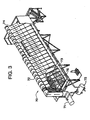
- Figure 3 is a schematic representation of a particular type of air cooled heat exchanger.
- Figure 4 is an IR spectrum for cryptomelane.
- Figure 5 is an XRD pattern for cryptomelane shown as counts using a square root scale versus the Bragg angle, 2 ⁇ .
- the present invention is directed to apparatus and a method for treating the atmosphere in which a stationary substrate has a pollutant treating composition thereon.
- a pollutant treating composition thereon.
- the atmosphere contacting surface of the substrate which has the pollutant treating composition thereon is one which is in direct contact with the ambient air.
- the substrate may be part of an existing air handling systems, such as those used in residential, commercial and industrial buildings, as well as power plants, oil refineries, chemical plants and any other facility in which air is drawn or forced over coatable surfaces.
- air handling systems include the outdoor components of heating, ventilation and air conditioning systems (referred to collectively as HVAC systems), industrial cooling systems, or any other system in which ambient air is naturally or purposefully forced into contact with a suitable substrate.
- the outdoor components of HVAC systems include fans for blowing or forcing ambient air over external heat transfer surfaces, such as cooling coils or fins.
- external heat transfer surfaces such as cooling coils or fins.
- the ambient air passes over the heat transfer surface and returns to the atmosphere.
- Suitable substrates for applying pollutant treating materials include any exposed surfaces, such as fan blades, duct and plenum surfaces, louvers, grills, motor housings, filtration media, screens, and heat transfer surfaces.
- heat transfer surfaces in HVAC include various coils, fins, plates or other surfaces which are designed to transfer heat to or from ambient air.
- substrates for catalytic pollutant treating materials are those surfaces which are at elevated temperatures above standard ambient temperature of about 25°C. Desirably, the substrates are of even higher temperatures, because many catalysts are more effective at higher temperatures.
- the coils or fins used to dissipate accumulated heat to the atmosphere are usually at temperatures above 25°C, and often much higher, depending on the coolant and operating parameters.
- Such heat dissipation apparatus can be as small as the external coils of a window air conditioner, or as large as the cooling towers used for commercial buildings.
- surfaces downstream from the heat transfer equipment such as plenum or duct walls, fan blades or grills, may also be at elevated temperatures for improved catalytic activity.
- Air handling systems are also used for many operations other than HVAC. Cooling towers are used to dissipate excess heat from various industrial sources. In power plants, cooling towers dissipate heat from relatively low temperature (but above 25°C) water or steam from which no further useful power can be extracted. In such systems, huge amounts of air are blown over heat transfer surfaces, or directly over or through the water being cooled.
- Suitable substrates for coating in accordance with the present invention include fan blades, walls of cooling towers, heat transfer surfaces and any other surfaces exposed to the flow of air.
- Such plants include large air handling systems and cooling towers, as generally discussed above.
- low temperature process steam is cooled to condense it to water prior to returning it to the boiler.
- Various operating units may include air cooling systems, such as external fins, to dissipate excess heat.
- many air handling systems provide a means, such as a fan, to circulate air ambient air over a heated surface for the purpose of cooling that surface.
- the fan only circulates air over the surface when the equipment is operating.
- the fan in such an intermittently operated system can be set to operate continuously to allow the pollutant treating process to continue even when the equipment is not otherwise operating.
- a temperature sensor can be provided in the air handling system, which can switch the circulating fan on or off in response to the temperature at one or more points in the system.
- the fan can be set to operate in response to some other external variable, such as the level of a particular pollutant, or at particular time intervals.
- a manual or remote control switch could be provided to actuate the fan of one or multiple air handling systems. For example, all of the air circulating fans in an area could be actuated simultaneously from a central controller in response to detection of a high level of a pollutant, or at particular times of the day.
- Pollutant treating compositions can be incorporated into various roofing materials, such as shingles, tar or tar paper, or may be sprayed or painted onto existing surfaces.
- road surfaces are also an excellent substrate to support pollutant treating compositions.
- road surfaces are heated by the sun and exposed to large flows of ambient air.
- exhaust from the vehicles on the roads results in localized concentrations of pollutants, rendering treated road surfaces particularly useful and efficient for reducing atmospheric pollution.
- the pollutant treating compositions can be incorporated into the paving materials, or applied as a topcoat to existing roadways.
- electrostatic precipitators are commonly found in dust handling equipment, such as bag houses, in which electric fields are used to remove dust from an air stream. In generating the electric fields, arcing may occur, which can result in the formation of large amounts of ozone. Treatment surfaces can be in the path of the air flow, as discussed above for air-handling systems, or can be on the exterior of the equipment or the enclosures housing the equipment where there may be high localized ozone concentrations.
- U.S. Pat. Appl. No. 08/412,525 also discusses applying pollutant treating compositions to free standing objects such as billboards or signs.
- U.S. Pat. No. 6,200,542 claims priority from U.S. 08/412,525.
- any free standing object with exposed surfaces could be used as a substrate in accordance with the present invention.
- such objects may include flagpoles, utility poles, including wires and equipment carried thereon, transmission antennae (which may also have localized high levels of ozone), storage tanks, bridges or the like.
- the object include a surface which is exposed to ambient air and can act as a substrate for carrying a pollutant treating composition.
- the surface is also heated, either naturally or by some source of applied heat.
- baffles, wings or other structures can be added to buildings at the locations of exceptional wind flow.
- wings could extend from the corners of buildings, taking advantage of the geometry of the building and the prevailing ambient wind currents.
- baffles or wings can either be solid or porous, with porous structures offering the ability to increase active surface area.
- An advantage of the present invention is that the atmosphere contacting surface useful to support a pollution treating composition can be any existing surface which lies in the path of a flow of ambient air. Accordingly, the apparatus and method of the present invention can be located on new components or retrofitted onto old ones.
- Pollutant treating compositions include catalyst compositions useful for catalyzing the conversion of pollutants present in the atmosphere to non-objectionable materials.
- adsorption compositions can be used as the pollutant treating composition to adsorb pollutants which can be destroyed upon adsorption, or stored for further treatment at a later time.
- Catalyst compositions can be used which can convert the pollutants to harmless compounds or to less harmful compounds.
- Useful and preferred catalyst compositions include compositions which catalyze the reaction of ozone to form oxygen.
- the compositions can be applied by coating at least one atmosphere contacting surface. Particularly preferred compositions catalyze the destruction of ozone at ambient conditions.
- catalyst compositions can be combined, and a combined coating applied to the atmosphere contacting surface.
- different surfaces or different parts of the same surface can be coated with different catalyst compositions.
- the method and apparatus of the present invention are preferably designed so that the pollutants can be treated at ambient conditions, requiring no heating means or incidental heat.
- the present invention is particularly useful for treating ozone by coating a surface with suitable catalysts useful to destroy such pollutants at ambient conditions.
- the percent conversion of ozone depends on the temperature and space velocity of the atmospheric air relative to the catalyst surface, and the temperature of the atmosphere contacting surface.
- the present invention in one embodiment results in at least reducing the ozone levels present in the atmosphere without the addition of any mechanical features or energy source to existing substrates. Additionally, the catalytic reaction of ozone to oxygen takes place at the normal ambient conditions experienced by the surfaces of these substrates so that minimal changes in the construction or method of operation are required.
- the ambient air may be heated by a heating means such as a heater or by incidental contact with a heated component of the stationary substrate.
- a heating means such as a heater or by incidental contact with a heated component of the stationary substrate.
- pollutants include carbon monoxide, hydrocarbons and nitrogen oxides. These pollutants can be treated at higher temperatures typically in the range of about 40°C to 450°C.
- Pollutant treating compositions can be coated onto ambient air contacting surfaces as described herein.
- catalyst compositions can be coated onto various metallic surfaces.
- the present invention can be applied to any stationary substrate with at least one atmosphere contacting surface comprising a pollutant treating composition located thereon.
- a pollutant treating composition located thereon.
- various pollutants including particulate matter and/or gaseous pollutants carried in the air can be catalytically reacted or adsorbed as the case may be by the pollutant treating composition located on the atmosphere contacting surface.
- FIG 1 is a schematic representation of one embodiment of an atmospheric pollutant treating device in accordance with the present invention, wherein the device is an air conditioning condenser.
- air conditioning condenser Such condensers are generally located outdoors, and are used to air cool an air conditioning fluid which is transported through coils in the unit.
- ambient air which may contain ozone enters condenser 20 through one or more inlet grills 21, passes through one or more heat exchangers 22, and exits the condenser through one or more outlet grills 23.
- the air is forced through the condenser by fan 24, which is shown in this embodiment mounted to the top of the condenser housing.
- the components of such a condenser can be arranged in any suitable operating configuration, provided that the ambient air passes in operative contact with a heat exchanger and returns to the atmosphere.
- the inlet can be on the sides, as shown, or on the bottom or top of the unit, and the outlet can be at the top as shown, or on the sides or bottom of the unit.
- the heat exchangers can be next to the inlets, as shown or next to the outlet.
- the fan can be between the heat exchangers and the outlet, as shown, or at any other location in the air stream.
- the condenser unit can be of any suitable shape, such as cubic, rectangular or cylindrical.
- a pollutant treating material is applied to a surface in the flow path of the air passing through the condenser. Suitable surfaces for this material are inlet grill 21, heat exchanger 22, outlet grill 23 or the blades of fan 24.
- the pollutant treating material includes an ozone catalyst, as discussed elsewhere in the present specification, it is generally more effective to operate at the highest available temperature. Because heat exchanger 22 is at an elevated temperature during normal operation of the condenser, the pollutant treating surface is therefore preferably located on the heat exchanger or down stream of the heat exchanger. In the embodiment shown in Figure 1, fan 24 and outlet grill 23 are both downstream from heat exchanger 22, and therefore would be preferred sites for the pollutant treating surface.
- a separate treatment device 25 which contains the pollutant treating surface.
- Device 25 may be at any suitable location in the airstream passing through the condenser. In the embodiment as shown, device 25 is mounted on the exterior of condenser 20, to receive the air flowing out of outlet grill 23. It will be readily seen that device 25 could be located anywhere in the airstream passing through the condenser, such as at the inlet, after the heat exchanger, or next to the fan. As discussed above, when a heat sensitive catalyst is being used, then device 25 is preferably located downstream of heat exchanger 22 to take advantage of the elevated temperature of the air passing therethrough.
- Treatment device 25 may be permanently or removably mounted to condenser 20. Preferably, device 25 is removably mounted to permit replacement or rejuvenation of the pollutant treating material.
- treatment device 25 includes a housing 26 which is attached to condenser 20 for receiving and holding a removable treatment cartridge 27.
- Treatment cartridge 27 may be of any suitable configuration, such as a honeycomb, filter pad, frame or screen coated with the catalyst or adsorbent material. The cartridge can be designed to be discarded after a single use, or to be cleaned or otherwise rejuvenated and reused.
- a dust filter may be provided to protect the active pollutant treating surface of treatment cartridge 27.
- Such a dust filter can be located anywhere in unit 20 or device 25 upstream of cartridge 27, or can even be integral with cartridge 27, upstream of the active surface.
- FIG 2 is a schematic representation of another embodiment of the present invention, in which a pollutant treating substrate is added to a commercial or industrial air cooled heat exchanger 40.
- a pollutant treating substrate is added to a commercial or industrial air cooled heat exchanger 40.
- Such heat exchangers are commonly used to condense low pressure steam into water, and may be found in industrial plants, power plants, commercial heating systems, and other steam handling facilities.
- steam is fed to header portion 42 (shown cut-away) of air-cooled heat exchanger 40, which is provided with top vents 44 for removing non-condensibles.
- the steam circulates back and forth through finned tube bundle 46 mounted in channel frame 48 where it is cooled and condensed by the air flow.
- the condensate is removed by bottom drains (not shown) and carried by drain line 50 to condensate tank 52.
- Air flow is provided by axial flow fan 54 which is shown mounted above the tube bundle 46, in a plenum 56 which channels the air flow to fan ring 58.
- Fan 54 is driven by electric motor 60, shown mounted below tube bundle 46, which is connected directly or indirectly to drive shaft 62. In operation, air is drawn by fan 54 through tube bundle 46 and out through fan ring 58.
- tube bundle 46 may be mounted horizontally (as shown), vertically or diagonally. Further, the tube bundle can be of any suitable design which allows condensing of steam passing therethrough.
- Fan 54 may be located on the output side of tube bundle 46 (as shown), at the inlet or even between separate heat exchange elements. Ducting to direct the air flow, may be included on the inlet and/or outlet sides of the heat exchanger, as well as protective screens or grills.
- the pollutant treating material may be applied to an existing surface in the flow path of the air passing through the heat exchanger. Suitable surfaces for this material include tube bundle 46, the blades of fan 54, and the inner surfaces of plenum 56 and fan ring 58. Alternatively, the material could be applied to any other ducting, screens or grills which are in the air flow path. As discussed elsewhere in the present specification, when the pollutant treating material includes an ozone catalyst or any other catalyst which is more effective at an elevated temperature, it is preferred to apply the material to a surface with the highest available temperature. Because tube bundle 46 is at an elevated temperature during normal operation of the condenser, the pollutant treating surface is preferably located on the tube bundle or downstream thereof. In the embodiment shown in Figure 2, fan 54, plenum 56 and fan ring 58 are all downstream of tube bundle 46, and would therefore be preferred sites for the pollutant treating surface.
- a separate treatment device may be provided, which contains the pollutant treating surface.
- a separate treatment device may be provided, which contains the pollutant treating surface.
- Such a device may be at any suitable location in the airstream passing through the heat exchanger.
- the treatment device could desirably be mounted at the outlet of fan ring 58, or within plenum 56 between tube bundle 46 and fan 54.
- the treatment device could also be located on the inlet side of tube bundle 46.
- the treatment device is preferably located downstream of tube bundle 46 to take advantage of the elevated temperature of the air passing therethrough.
- the treatment device for the present air-cooled heat exchanger 40 may be permanently or removably mounted to the unit.
- the device is removably mounted to permit replacement or rejuvenation of the pollutant treating material.
- the treatment device includes a housing which is attached to heat exchanger 40 for receiving and holding a removable treatment substrate.
- the treatment substrate may be of any suitable configuration, and can be designed to be discarded after a single use, or to be cleaned or otherwise rejuvenated and reused.
- a high surface area structure such as a ceramic or metal honeycomb, can provide an excellent substrate to support the pollutant treating material.
- the high surface area structure can also be any type of filter, screen or grill capable of supporting the treatment material.
- the substrate can be a separate heat exchanger, in which a separate source of heat may be provided to increase the working temperature of the pollutant treating material.
- the separate source of heat can be a side stream of the steam which is entering or the condensate which is exiting the principal heat exchanger 40, or an independent heated stream. Alternatively, electric or combustion heating could be used.
- FIG. 3 is a schematic representation of a particular type of air cooled heat exchanger 70, which is in use in some power plants to condense large volumes of low pressure steam.
- Steam enters the unit at inlet 71, and is distributed through a top-mounted plenum 72.
- the steam passes through diagonally disposed heat exchange tubes 73 mounted in housing 74, and the condensate is collected in condensate tank 75.
- Air flow is provided by bottom mounted forced draft fans 76, which direct the air upwardly through the tube bundles and then to the atmosphere.
- the diagonally disposed heat exchange tubes may be directly coated with the pollutant treating material.
- separate pollutant treating devices may be permanently or removably affixed to the inside or outside of the diagonal surface of housing 74.
- the treating devices are pivotably mounted to the housing so that they can be swung out of the way to permit cleaning and servicing of the underlying tubes 73.
- test units of catalyzed automobile radiators can be attached to, or simply laid on, the exterior of such a heat exchanger to test the catalysts of the present invention.
- the pollutant treating composition is a catalytic composition.
- Useful and preferred catalyst compositions are compositions which can catalytically cause the reaction of targeted pollutants at the space velocity of the air as it contacts the surface, and at the temperature of the surface at the point of contact. Typically, these catalyzed reactions will be in the temperature range at the atmosphere contacting surface of from 0°C to 130°C, more typically 20°C to 105°C and yet more typically from about 40°C to 100°C.
- There is no limit on the efficiency of the reaction as long as some reaction takes place.
- Useful conversion efficiencies are preferably at least about 5% and more preferably at least about 10%.
- Preferred conversions depend on the particular pollutant and pollutant treating composition. Where ozone is treated with a catalytic composition on an atmosphere contacting surface it is preferred that the conversion efficiency be greater than about from 30% to 40%, preferably greater than 50%, and more preferably greater than 70%. Preferred conversion for carbon monoxide is greater than 30% and preferably greater than 50%. Preferred conversion efficiency for hydrocarbons and partially oxygenated hydrocarbons is at least 10%, preferably at least 15%, and most preferably at least 25%. These conversion rates are particularly preferred where the atmosphere contacting surface is at ambient operating conditions of up to about 110°C. These temperatures are the surface temperatures typically experienced during normal operation of atmosphere contacting surfaces of the vehicle including the surfaces of the radiator and air conditioning condenser.
- the conversion efficiency be greater than 90% and more preferably greater than 95%.
- the conversion efficiency is based on the mole percent of the particular pollutants in'the air which react in the presence of the catalyst composition.
- Ozone treating catalyst compositions consist of manganese oxides, such as for example manganese dioxide, including non stoichiometric manganese dioxide (e.g., MnO (1.5-2.0) ), and/or Mn 2 O 3 which are substantially free of anions.
- manganese dioxides which are nominally referred to as MnO 2 have a chemical formula wherein the molar ratio of manganese to oxide is about from 1.5 to 2.0, such as Mn 8 O 16 . Up to 100 percent by weight of manganese dioxide MnO 2 can be used in catalyst compositions to treat ozone.
- Useful and preferred manganese dioxides are alpha manganese dioxides nominally having a molar ratio of manganese to oxygen of from 1 to 2.
- Useful alpha manganese dioxides are disclosed in U.S. Patent No. 5,340,562 to O'Young, et al.; also in O'Young, Hydrothermal Synthesis of Manganese Oxides with Tunnel Structures presented at the Symposium on Advances in Zeolites and Pillared Clay Structures presented before the Division of Petroleum Chemistry, Inc. American Chemical Society New York City Meeting, August 25-30, 1991 beginning at page 342, and in McKenzie, the Synthesis of Birnessite, Cryptomelane, and Some Other Oxides and Hydroxides of Manganese, Mineralogical Magazine, December 1971, Vol. 38, pp. 493-502.
- the preferred alpha manganese dioxide is a 2 x 2 tunnel structure which can be hollandite (BaMn 8 O 16 .xH 2 O), cryptomelane (KMn 8 O 16 .xH 2 O), manjiroite (NaMn 8 O 16 .xH 2 O) and coronadite (PbMn 8 O 16 .xH 2 O).
- the manganese dioxides useful in the present. invention preferably have a surface area of greater than 150 m 2 /g, more preferably greater than 200 m 2 /g, yet more preferably greater than 250 m 2 /g and most preferably greater than 275 m 2 /g.
- the upper range of such materials can be as high as 300 m 2 /g, 325 m 2 /g or even 350 m 2 /g.
- Preferred materials are in the range of 200-350 m 2 /g, preferably 250-325 m 2 /g and most preferably 275-300 m 2 /g.
- the composition preferably comprises a binder as of the type described below with preferred binders being polymeric binders.
- compositions comprising the cryptomelane form of alpha manganese oxide, which also contain a polymeric binder can result in greater than 50%, preferably greater than 60% and most preferably from 75-85% conversion of ozone in a concentration range of from 0 to 400 parts per billion (ppb) and an air stream moving across a radiator at space velocity of from 300,000 to 650,000 reciprocal hours.
- ppb parts per billion
- the preferred cryptomelane manganese dioxide has a crystallite size ranging from 2 to 10 and preferably from less than 5 nm. It can be calcined at a temperature range of from 250°C to 550°C and preferably below 500°C and greater than 300°C for at least 1.5 hours and preferably at least 2 hours up to about 6 hours.
- the preferred cryptomelane can be made in accordance described in the above referenced articles and patents to O'Young and McKenzie.
- the cryptomelane can be made by reacting a manganese salt including salts selected from the group consisting MnCl 2 , Mn(NO 3 ) 2 , MnSO 4 and Mn(CH 3 COO) 2 with a permanganate compound.
- Cryptomelane is made using potassium permanganate; hollandite is made using barium permanganate; coronadite is made using lead permanganate; and manjiroite is made using sodium permanganate.
- alpha manganese useful in the present invention can contain one or more of hollandite, cryptomelane, manjiroite or coronadite compounds. Even when making cryptomelane minor amounts of other metal ions such as sodium may be present. Useful methods to form the alpha manganese dioxide are described in the above references.
- the preferred alpha manganese for use in accordance with the present invention is cryptomelane.
- the cryptomelane is "clean" or substantially free of inorganic anions, particularly on the surface. Such anions could include chlorides, sulfates and nitrates which are introduced during the method to form cryptomelane.
- An alternate method to make the clean cryptomelane is to react a manganese carboxylate, preferably manganese acetate, with potassium permanganate. It has been found that the use of such a material which has been calcined is "clean".
- the use of material containing inorganic anions can result in conversion of ozone to oxygen of up to about 60%.
- the use of cryptomelane with a "clean" surface results in conversions of up about 80%.
- the carboxylates are burned off during the calcination process.
- inorganic anions remain on the surface even during calcination.
- the inorganic anions such as sulfates can be washed away with an aqueous solution or a slightly acidic aqueous solution.
- the alpha manganese dioxide is a "clean" alpha manganese dioxide.
- the cryptomelane can be washed at from about 60°C to 100°C for about one-half hour to remove a significant amount of sulfate anions.
- the nitrate anions may be removed in a similar manner.
- the "clean" alpha manganese dioxide is characterized as having an IR spectra as illustrated in Figure 4 and in X-ray diffraction (XRD) pattern as illustrated in Figure 5.
- Such a cryptomelane preferably has a surface area greater than 200 m 2 /g and more preferably greater than 250 m 2 /g.
- a preferred method of making cryptomelane useful in the present invention comprises mixing an aqueous acidic manganese salt solution with a potassium permanganate solution.
- the acidic manganese salt solution has a pH of from 0.5 to 3 and can be made acidic using any common acid, preferably acetic acid at a concentration of from 0.5 to 5.0 normal and more preferably from 1.0 to 2.0 normal.
- the mixture forms a slurry which is stirred at a temperature range of from 50°C to 110°C.
- the slurry is filtered and the filtrate is dried at a temperature range of from 75°C to 200°C.
- the resulting cryptomelane crystals have a surface area of typically in the range of from 200 m 2 /g to 350 m 2 /g.
- FIG. 4 A review of the IR spectrum for the most preferred cryptomelane, shown in Figure 4 is characterized by the absence of peaks assignable to carbonate, sulfate and nitrate groups. Expected peaks for carbonate groups appear in the range of from 1320 to 1520 wavenumbers; and for sulfate groups appear in the range of from 950 to 1250 wavenumbers.
- Figure 5 is a powder X-ray diffraction pattern for high surface area cryptomelane prepared in Example 2. The X-ray pattern for cryptomelane useful in the present invention is characterized by broad peaks resulting from small crystallite size ( ⁇ 5-10nm).
- Approximate peak positions ( ⁇ 0.15°2 ⁇ ) and approximate relative intensities ( ⁇ 5) for cryptomelane using CuK ⁇ radiation as shown in Figure 5 are: 2 ⁇ /Relative Intensities - 12.1/9; 18/9; 28.3/10; 37.5/100; 41.8/32; 49.7/16; 53.8/5; 60.1/13; 55.7/38; and 68.0/23.
- a preferred method of making cryptomelane useful in the present invention comprises mixing an aqueous acidic manganese salt solution with a potassium permanganate solution.
- the acidic manganese salt solution preferably has a pH of from 0.5 to 3.0 and can be made acidic using any common acid, preferably acetic acid at a concentration of from 0.5 to 5.0 normal and more preferably from 1.0 to 2.0 normal.
- the mixture forms a slurry which is stirred at a temperature range of from 50°C to 110°C.
- the slurry is filtered and the filtrate is dried at a temperature range of from 75°C to 200°C.
- the resulting cryptomelane crystals have a surface area of typically in the range of from 200 m 2 /g to 350 m 2 /g.
- a suitable support material such as a refractory oxide support.
- the preferred refractory oxide can be selected from the group consisting of silica, alumina, titania, ceria, zirconia and chromia, and mixtures thereof. More preferably, the support is at least one activated, high surface area compound selected from the group consisting of alumina, silica, titania, silica-alumina, silica-zirconia, alumina silicates, alumina zirconia, alumina-chromia and alumina-ceria.
- the refractory oxide can be in suitable form including bulk particulate form typically having particle sizes ranging from about 0.1 to about 100 and preferably 1 to 10 ⁇ m or in sol form also having a particle size ranging from about 1 to about 50 and preferably about 1 to about 10 nm.
- a preferred titania sol support comprises titania having a particle size ranging from about 1 to about 10, and typically from about 2 to 5 nm.
- a coprecipitate of a manganese oxide and zirconia is also useful as a preferred support.
- This composition can be made as recited in U.S. Patent No. 5,283,041 incorporated herein by reference.
- this coprecipitated support material preferably comprises in a ratio based on the weight of manganese and zirconium metals from 5:95 to 95:5; preferably 10:90 to 75:25; more preferably 10:90 to 50:50; and most preferably from 15:85 to 50:50.
- a useful and preferred embodiment comprises a Mn:Zr weight ratio of 20:80.
- a zirconia oxide and manganese oxide material may be prepared by mixing aqueous solutions of suitable zirconium oxide precursors such as zirconium oxynitrate, zirconium acetate, zirconium oxychioride, or zirconium oxysulfate and a suitable manganese oxide precursor such as manganese nitrate, manganese acetate, manganese dichloride or manganese dibromide, adding a sufficient amount of a base such as ammonium hydroxide to obtain a pH of 8-9, filtering the resulting precipitate, washing with water, and drying at 450°-500°C.
- suitable zirconium oxide precursors such as zirconium oxynitrate, zirconium acetate, zirconium oxychioride, or zirconium oxysulfate
- a suitable manganese oxide precursor such as manganese nitrate, manganese acetate, manganese dichloride or manganese dibromid
- a useful support for a catalyst to treat ozone is selected from a refractory oxide support, preferably alumina and silica-alumina with a more preferred support being a silica-alumina support comprising from about 1% to 10% by weight of silica and from 90% to 99% by weight of alumina.
- a titania support which has been found useful since it results in a catalyst composition having enhanced ozone conversion as well as significant conversion of carbon monoxide and low molecular weight olefins.
- high surface area, macroporous refractory oxides preferably alumina and titania having a surface area of greater than 150 m 2 /g and preferably ranging from about 150 to 350, preferably from 200 to 300, and more preferably from 225 to 275 m 2 /g; a porosity of greater than 0.5 cc/g, typically ranging from 0.5 to 4.0 and preferably about from 1 to 2 cc/g measured based on mercury porosometry; and particle sizes range from 0.1 to 10 ⁇ m.
- a useful material is Versal GL alumina having a surface area of about 260 m 2 /g, a porosity of 1.4 to 1.5 cc/g and supplied by LaRoche Industries.
- a preferred titania sol support comprises titania having a particle size ranging from about 1 to about 10, and typically from about 2 to 5 nm.
- a preferred bulk titania has a surface area of about from 25 to 120 m 2 /g, and preferably from 50 to 100 m 2 /g; and a particle size of about from 0.1 to 10 ⁇ m.
- a specific and preferred bulk titania support has a surface area of 45-50 m 2 /g, a particle size of about 1 ⁇ m, and is sold by DeGussa as P-25.
- a preferred silica-zirconia support comprises from 1 to 10 percent silica and 90 to 99 percent zirconia.
- Preferred support particles have high surface area, e.g. from 100 to 500 square meters per gram (m 2 /g) surface area, preferably from 150 to 450 m 2 /g, more preferably from 200 to 400 m 2 /g, to enhance dispersion of the catalytic metal component or components thereon.
- the preferred refractory metal oxide support also has a high porosity with pores of up to about 145 nm radius, e.g., from about 0.75 to 1.5 cubic centimeters per gram (cm 3 /g), preferably from about 0.9 to 1.2 cm 3 /g, and a pore size range of at least about 50% of the porosity being provided by pores of 5 to 100 nm in radius.
- the catalytic compositions employed in the present invention preferably comprise a binder which acts to adhere the composition and to provide adhesion to the atmosphere contacting surface.
- a preferred binder is a polymeric binder used in amounts of from 0.5 to 20, more preferably 2 to 10, and most preferably to 2 to 5 percent by weight of binder based on the weight of the composition.
- the binder is a polymeric binder which can be a thermosetting or thermoplastic polymeric binder.
- the polymeric binder can have suitable stabilizers and age resistors known in the polymeric art.
- the polymer can be a plastic or elastomeric polymer.
- thermosetting, elastomeric polymers introduced as a latex into the catalyst into a slurry of the catalyst composition, preferably an aqueous slurry.
- the binder material can crosslink .providing a suitable support which enhances the integrity of the coating, its adhesion to the atmosphere contacting surface and provides structural stability under vibrations encountered in motor vehicles.
- the use of preferred polymeric binder enables the pollutant treating composition to adhere to the atmosphere contacting surface without the necessity of an undercoat layer.
- the binder can comprise water resistant additives to improve water resistance and improve adhesion. Such additives can include fluorocarbon emulsions and petroleum wax emulsions.
- Useful polymeric compositions include polyethylene, polypropylene, polyolefin copolymers, polyisoprene, polybutadiene, polybutadiene copolymers, chlorinated rubber, nitrile rubber, polychloroprene, ethylene-propylene-diene elastomers, polystyrene, polyacrylate, polymethacrylate, polyacrylonitrile, poly(vinyl esters), poly(vinyl halides), polyamides, cellulosic polymers, polyimides, acrylics, vinyl acrylics and styrene acrylics, poly vinyl alcohol, thermoplastic polyesters, thermosetting polyesters, poly(phenylene oxide), poly(phenylene sulfide), fluorinated polymers such as poly(tetrafluoroethylene) polyvinylidene fluoride, poly(vinylfluoride) and chloro/fluoro copolymers such as ethylene chlorotrifluoroethylene copolymer, polyamide,
- Particularly preferred polymers and copolymers are vinyl acrylic polymers and ethylene vinyl acrylic copolymers.
- a preferred vinyl acetate polymer is across linking polymer sold by National Starch and Chemical Company as Xlink 2833. It is described as a vinyl acrylic polymer having a Tg of -15°C, 45% solids, a pH of 4.5 and a viscosity of 300 cps. In particular, it is indicated to have vinyl acetate CAS No. 108-05-4 in a concentration range of less than 0.5 percent. It is indicated to be a vinyl acetate copolymer.
- Other preferred vinyl acetate copolymers which are sold by the National Starch and Chemical Company include Dur-O-Set E-623 and Dur-O-Set E-646.
- Dur-O-Set E-623 is indicated to be ethylene vinyl acetate copolymers having a Tg of 0°C, 52% solids, a pH of 5.5 and a viscosity of 200 cps.
- Dur-O-Set E-646 is indicated to be an ethylene vinyl acetate copolymer with a Tg of -12°C, 52% solids, a pH of 5.5 and a viscosity of 300 cps.
- zirconium compound An alternate and useful binding material is the use of a zirconium compound.
- Zirconyl acetate is preferred zirconium compound used. It is believed that zirconia acts as a high temperature stabilizer, promotes catalytic activity, and improves catalyst adhesion. Upon calcination, zirconium compounds such as zirconyl acetate are converted to ZrO 2 which is believed to be the binding material.
- Various useful zirconium compounds include acetates, hydroxides, nitrates, etc. for generating ZrO 2 in catalysts. In the case of using zirconyl acetate as a binder for the present catalysts, ZrO 2 will not be formed unless the radiator coating is calcined.
- zirconyl acetate has not decomposed to zirconium oxide but instead has formed a cross linked network with the pollutant treating material. Accordingly, the use of any zirconium containing compounds in the present catalysts are not restricted only to zirconia. Additionally, the zirconium compounds can be used with other binders such as the polymeric binder recited above.
- the method of the present invention includes forming a mixture comprising the catalytically active manganese component and water.
- the catalytically active material can be on a suitable support, preferably a refractory oxide support.
- the mixture can be milled, calcined and optionally reduced.
- the calcining step can be conducted prior to adding the polymeric binder. It is also preferred to reduce the catalytically active material prior to adding the polymeric binder.
- the slurry comprises a carboxylic acid compound or polymer containing carboxylic acid in an amount to result in a pH of about from 3 to 7, typically 3 to 6, and preferably from 0.5 to 15 weight percent of glacial acetic acid based on the weight of the catalytically active material and acetic acid.
- the amount of water can be added as suited to attain a slurry of the desired viscosity.
- the percent solids are typically 20 to 50 and preferably 30 to 40 percent by weight.
- the preferred vehicle is deionized water (D.I.).
- the acetic acid can be added upon forming the mixture of the catalytically active material, which may have been calcined, with water. Alternatively, the acetic acid can be added with the polymeric binder.
- a preferred composition to treat ozone using manganese dioxide as the catalyst can be made using about 1,500 g of manganese dioxide which is mixed with 2,250 g of deionized water and 75 g or acetic acid.
- the mixture is combined in a 1 gallon ballmill and ballmilled for about 8 hours until approximately 90% of the particles are less than 8 micrometers.
- the ballmill is drained and 150 g of polymeric binder is added.
- the mixture is then blended on a rollmill for 30 minutes. The resulting mixture is ready for coating onto a suitable substrate.
- the pollutant treating composition can be applied to the atmosphere contacting surface by any suitable means such as spray coating, powder coating, or brushing or dipping the surface into a catalyst slurry.
- the atmosphere contacting surface is preferably cleaned to remove surface dirt, particularly oils which could result in poor adhesion of the pollutant treating composition to the surface. Where possible, it is preferred to heat the substrate on which the surface is located to a high enough temperature to volatilize or burn off surface debris and oils.
- the substrate on which there is an atmosphere contacting surface is made of a material which can withstand elevated temperatures such as an aluminum radiator
- the substrate surface can be treated in such a manner as to improve adhesion to the catalyst composition, preferably the ozone carbon monoxide, and/or hydrocarbon catalyst composition.
- One method is to heat the aluminum substrate such as the radiator to a sufficient temperature in air for a sufficient time to. form a thin layer of aluminum oxide on the surface. This helps clean the surface by removing oils which may be detrimental to adhesion.
- a sufficient layer of oxidized aluminum has been found to be able to be formed by heating the radiator in air for from 0.5 to 24 hours, preferably from 8 to 24 hours and more preferably from 12 to 20 hours at from 350°C to 500°C, preferably from 400 to 500°C and more preferably 425 to 475°C.
- sufficient adhesion without the use of an undercoat layer has been attained where an aluminum radiator has been heated at 450°C for 16 hours in air. This method is particularly useful when applying the coating to new surfaces prior to assembly, either as original equipment or replacement.
- Adhesion may improve by applying an undercoat or precoat to the substrate.
- Useful undercoats or precoats include refractory oxide supports of the type discussed above, with alumina preferred.
- a preferred undercoat to increase adhesion between the atmosphere contacting surface and an overcoat of an ozone catalyst composition is described in commonly assigned U.S. Patent No. 5,422,331.
- the undercoat layer is disclosed as comprising a mixture of fine particulate refractory metal oxide and a sol selected from silica, alumina, zirconia and titania sols.
- surfaces on existing stationary surfaces can be coated in place.
- the catalyst composition can be applied directly to the surface. Where additional adhesion is desired, an undercoat can be used as recited above.
- a support material such as activated alumina, silica-alumina, bulk titania, titanium sol, silica zirconia, manganese zirconia and others as recited can be formed into a slurry and coated on the substrate preferably with a silica sol to improve adhesion.
- the precoated substrate can subsequently be coated with manganese nitrate.
- the coated substrate can then be heated in an oven in air for sufficient time (0.5 to 12 hours at 350° C to 550°C) to calcine the manganese components to form the oxides thereof.
- the present invention can additionally comprise adsorption compositions supported on the atmosphere contacting surface.
- the adsorption compositions can be used to adsorb gaseous pollutants such as hydrocarbons and sulfur dioxide as well as particulate matter such as particulate hydrocarbon, soot, pollen, bacteria and germs.
- Useful supported compositions can include adsorbents such as zeolite to adsorb hydrocarbons.
- Useful zeolitic compositions are described in Publication No. WO 94/27709 published December 8, 1994 and entitled Nitrous Oxide Decomposition Catalyst. Particularly preferred zeolites are Beta zeolite, and dealuminated Zeolite Y.
- Carbon, preferably activated carbon can be formed into carbon adsorption compositions comprising activated carbon and binders such as polymers as known in the art.
- the carbon adsorption composition can be applied to the atmosphere contacting surface.
- Activated carbon can adsorb hydrocarbons, volatile organic components, bacteria, pollen and the like.
- Yet another adsorption composition can include components which can adsorb SO 3 .
- a particularly useful SO 3 adsorbent is calcium oxide. The calcium oxide is converted to calcium sulfate.
- the calcium oxide adsorbent compositions can also contain a vanadium or platinum catalyst which can be used to convert sulfur dioxide to sulfur trioxide which
- the present invention additionally contemplates additionally to the reduction of the level of ozone the catalytic oxidation and/or reduction of hydrocarbons, nitrogen oxides and residual carbon monoxide using conventional three way catalysts supported on electrically heated catalysts such as are known in the art.
- the electrically heated catalysts can be located on an electrically heated catalyst monolith.
- Such electrically heated catalyse substrates are known in the art and are disclosed in references such as U.S. Patent Nos. 5,308,591 and 5,317,869.
- the electrically heated catalyst is a metal honeycomb having a suitable thickness in the flow direction, preferably of from 0.3175 to 30.48 cm (1/8 inch to 12 inches), and more preferably 1.27 to 7.62 cm (0.5 to 3 inches).
- Preferred supports are monolithic carriers of the type having a plurality of fine, parallel gas flow passages extending therethrough from an inlet face to an outlet face of the carrier so that the passages are open to air flow entering from the front and passing through the monolith in the direction toward the fan.
- the passages are essentially straight from their inlet to their outlet and are defined by walls in which the catalytic material is coated as a wash coat so that the gases flowing through the passages contact the catalytic material.
- the flow passages of the monolithic carrier are thin wall channels which can be of any suitable cross-sectional shape and size such as trapezoidal, rectangular, square, sinusoidal, hexagonal, oval, circular or formed from metallic components which are corrugated and flat as are known in the art.
- such structures may contain from about 9.3 to 93 or more gas inlet openings ("cells") per square centimeter (60 to 600 or more gas inlet openings ("cells") per square inch) of cross section.
- the monolith may be made of any suitable material and is preferably capable of being heated upon application of an electric current.
- a useful catalyst to apply is the three way catalyst (TWC) as recited above which can enhance the oxidation of hydrocarbons and carbon monoxide as well as the reduction of nitrogen oxides.
- Useful TWC catalysts are recited in U.S. Patent Numbers 4,714,694; 4,738,947; 5,010,051; 5.057,483; and 5,139,992.
- a test apparatus comprising an ozone generator, gas flow control equipment, water bubbler, chilled mirror dew point hygrometer, and ozone detector was used to measure the percent ozone destroyed by catalyst samples.
- Ozone was generated in situ utilizing the ozone generator in a flowing gas stream comprised of air and water vapor. The ozone concentration was measured using the ozone detector and the water content was determined utilizing the dew point hygrometer.
- Samples were tested as 25°C using inlet ozone concentrations of 4.5 to 7 parts per million (ppm) in a gas stream flowing at approximately 1.5 L/minute with a dew point between 15°C and 17°C. Samples were tested as particles sized to -25/+45 mesh held between glass wool plugs in a 0.635 cm (1/4") I.D. Pyrex® glass tube. Tested samples filled a 1 cm portion of the glass tube.
- Example 2 This example is intended to illustrate that the method of Example 2 generated "clean" high surface area cryptomelane for which the ozone destruction performance was not further enhanced by calcination and washing.
- a 20 gram portion of the sample represented by Example 2 was calcined in air at 200°C for 1 hour, cooled to room temperature, then washed at 100°C in 200 mL of D.I. water by stirring the slurry for 30 minutes. The resulting product was filtered and dried at 100°C in an oven.
- the sample was determined to have BET Multi-Point surface area of 265 m 2 /g. Ozone destruction testing on the sample showed 85% conversion.
- a comparison to the testing of the sample of Example 2 demonstrated that no benefit in ozone conversion was realized from the washing and calcination of the sample of Example 2.
- Samples of high surface area cryptomelane were obtained from commercial suppliers and modified by calcination and/or washing. As received and modified powders were tested for ozone decomposition performance according to the method of Example 3 and characterized by powder X-ray diffraction, infrared spectroscopy, and BET surface area measurements by nitrogen adsorption.
Landscapes
- Engineering & Computer Science (AREA)
- Chemical & Material Sciences (AREA)
- Environmental & Geological Engineering (AREA)
- Chemical Kinetics & Catalysis (AREA)
- Analytical Chemistry (AREA)
- General Chemical & Material Sciences (AREA)
- Oil, Petroleum & Natural Gas (AREA)
- Biomedical Technology (AREA)
- Health & Medical Sciences (AREA)
- Exhaust Gas Treatment By Means Of Catalyst (AREA)
- Catalysts (AREA)
- Treating Waste Gases (AREA)
- Separation Of Gases By Adsorption (AREA)
- Disinfection, Sterilisation Or Deodorisation Of Air (AREA)
- Air-Conditioning For Vehicles (AREA)
- Crystals, And After-Treatments Of Crystals (AREA)
- Cleaning Or Drying Semiconductors (AREA)
- Cleaning In General (AREA)
Claims (41)
- Procédé de traitement de l'atmosphère pour réduire le niveau d'ozone contenu dans celle-ci, le procédé comprenant le transfert de l'air ambiant par contact opérationnel sur une surface de traitement des émissions polluantes dotée d'un matériau de traitement des émissions polluantes, dans lequel la surface de traitement des émissions polluantes est disposée sur un substrat stationnaire, le matériau de traitement des émissions polluantes comprenant une composition catalytique consistant en oxyde de manganèse sensiblement dépourvu d'anions.
- Procédé selon la revendication 1 dans lequel l'étape de transfert de l'air par contact opérationnel sur la surface de traitement des émissions polluantes comprend le retrait ou le forçage de façon active par contact opérationnel sur la surface.
- Procédé selon la revendication 2 dans lequel l'air ambiant est activement retiré ou forcé au moyen d'un système de manutention de l'air, et la surface de traitement des émissions polluantes est disposée sur un composant de contact de l'air dudit système de manutention de l'air.
- Procédé selon la revendication 3 dans lequel le système de manutention de l'air comprend un ventilateur muni de pâles de ventilateur et la surface de traitement des émissions polluantes est disposée sur les pâles du ventilateur.
- Procédé selon la revendication 3 dans lequel le système de manutention de l'air comprend une ou plusieurs surfaces de contact de l'air sélectionnées parmi le groupe consistant en des filtres, des écrans et des grilles, et la surface de traitement des émissions polluantes est disposée sur une ou plusieurs desdites surfaces de contact de l'air.
- Procédé selon la revendication 3 dans lequel le système de manutention de l'air comprend une ou plusieurs surfaces de contact de l'air amovibles, et la surface de traitement des émissions polluantes est disposée sur une ou plusieurs desdites surfaces de contact de l'air amovibles.
- Procédé selon la revendication 3 dans lequel le système de manutention de l'air comprend des surfaces de transfert de chaleur et la surface de traitement des émissions polluantes est disposée sur les surfaces de transfert de chaleur ou en aval des surfaces de transfert de chaleur.
- Procédé selon la revendication 7 dans lequel le système de manutention de l'air comprend en outre une ou plusieurs surfaces de contact de l'air amovibles situées en aval des surfaces de transfert de chaleur, et la surface de traitement des émissions polluantes est disposée sur une ou plusieurs desdites surfaces de contact de l'air amovibles.
- Procédé selon la revendication 7 dans lequel lesdites surfaces de transfert de chaleur se situent à une température supérieure à 25°C pendant au moins une période de fonctionnement normal dudit système de manutention de l'air.
- Procédé selon la revendication 3 dans lequel la surface de traitement des émissions polluantes est l'une qui se situe à une température supérieure à 25°C pendant au moins une période de fonctionnement normal dudit système de manutention de l'air.
- Procédé selon la revendication 1 dans lequel la surface de traitement des émissions polluantes est l'une qui atteint normalement une température supérieure à 25°C pendant au moins une période de temps qui peut être mesurée.
- Procédé selon la revendication 1 dans lequel le matériau de traitement des émissions polluantes est contenu dans la peinture qui est appliquée à la surface de traitement des émissions polluantes.
- Procédé selon la revendication 1 dans lequel l'air est transféré par contact opérationnel sur la surface de traitement des émissions polluantes par la circulation naturelle de l'air.
- Procédé selon la revendication 11 dans lequel ladite surface de traitement des émissions polluantes comprend une surface de contact de l'air ambiant sur l'extérieur d'une structure.
- Procédé selon la revendication 1 comprenant en outre l'augmentation de la température de l'air ambiant avant le transfert de l'air ambiant sur la surface de contact de l'air ambiant.
- Procédé selon la revendication 1 comprenant en outre l'augmentation de la température de la surface de contact de l'air avant le transfert de l'air ambiant sur la surface de contact de l'air ambiant.
- Procédé selon la revendication 1 comprenant en outre la rénovation de façon périodique de la surface de traitement des émissions polluantes.
- Procédé selon la revendication 17 dans lequel ladite rénovation comprend le nettoyage de la surface de traitement des émissions polluantes.
- Procédé selon la revendication 17 dans lequel ladite rénovation comprend l'ajout de nouveau matériau de traitement des émissions polluantes sur la surface de traitement des émissions polluantes.
- Procédé selon la revendication 19 comprenant en outre le retrait d'au moins certains des matériaux de traitement des émissions polluantes existants, de la surface de traitement des émissions polluantes avant d'ajouter le nouveau matériau.
- Procédé selon la revendication 1 dans lequel l'air ambiant contient également des contaminants non gazeux, le procédé comprenant en outre le filtrage de l'air ambiant pour retirer au moins certains des contaminants non gazeux avant de transférer l'air par contact sur la surface de traitement des émissions polluantes.
- Dispositif pour le traitement de l'atmosphère pour réduire le niveau d'ozone contenu dans celle-ci, le dispositif comprenant :(a) un substrat stationnaire muni d'au moins une surface de contact de l'air ;(b) un matériau de traitement des émissions polluantes disposé sur ladite surface de contact de l'air, le matériau de traitement des émissions polluantes comprenant une composition catalytique consistant en oxyde de manganèse dépourvu d'anions ; et(c) des moyens de transfert de l'air pour le transfert de l'air ambiant par contact opérationnel sur le matériau de traitement des émissions polluantes.
- Dispositif selon la revendication 22 dans lequel les moyens de transfert de l'air comprennent un dispositif pour retirer ou forcer de manière active l'air ambiant par contact opérationnel sur le matériau de traitement des émissions polluantes.
- Dispositif selon la revendication 23 dans lequel le dispositif comprend un système de manutention de l'air, et le matériau de traitement des émissions polluantes est disposé sur une surface de contact de l'air d'un composant dudit système de manutention de l'air.
- Dispositif selon la revendication 24 dans lequel le système de manutention de l'air comprend un ventilateur muni de pâles de ventilateur et le matériau de traitement des émissions polluantes est disposé sur les pâles du ventilateur.
- Dispositif selon la revendication 24 dans lequel le système de manutention de l'air comprend un ou plusieurs composants sélectionné à partir du groupe consistant en des filtres, des écrans, et des grilles, et le matériau de traitement des émissions polluantes est disposé sur une ou plusieurs surfaces de contact de l'air desdits composants.
- Dispositif selon la revendication 24 dans lequel le système de manutention de l'air comprend un ou plusieurs composants amovibles muni de surfaces de contact de l'air, et le matériau de traitement des émissions polluantes est disposé sur une ou plusieurs surfaces de contact de l'air desdits composants amovibles.
- Dispositif selon la revendication 24 dans lequel le système de manutention de l'air comprend un échangeur de chaleur muni d'une surface de transfert de chaleur et le matériau de traitement des émissions polluantes est disposé sur la surface de transfert de chaleur ou sur une surface de contact de l'air d'un composant en aval à partir de la surface de transfert de chaleur.
- Dispositif selon la revendication 28, dans lequel le système de manutention de l'air comprend en outre un ou plusieurs composants amovibles situés en aval de la surface de transfert de chaleur, et le matériau de traitement des émissions polluantes est disposé sur une ou plusieurs surfaces de contact de l'air desdits composants amovibles.
- Dispositif selon la revendication 28 dans lequel ladite surface de transfert de chaleur est l'une située à une température supérieure à 25°C pendant au moins une période de fonctionnement normal dudit système de manutention de l'air.
- Dispositif selon la revendication 24 dans lequel la surface de contact de l'air est l'une située à une température supérieure à 25°C pendant au moins une période de fonctionnement normale dudit système de manutention de l'air.
- Dispositif selon la revendication 22 dans lequel la surface de contact de l'air est l'une qui atteint normalement une température supérieure à 25°C pendant au moins une période de temps qui peut être mesurée.
- Dispositif selon la revendication 22 comprenant en outre de la peinture qui est appliquée sur la surface de contact de l'air, et dans lequel le matériau de traitement des émissions polluantes est contenu dans la peinture.
- Dispositif selon la revendication 22 dans lequel les moyens de transfert de l'air sont la circulation naturelle de l'air.
- Dispositif selon la revendication 34 comprenant une structure avec le matériau de traitement des émissions polluantes disposée sur une surface extérieure de contact de l'air de la structure.
- Dispositif selon la revendication 22 comprenant en outre des moyens pour augmenter la température de l'air ambiant avant le transfert de l'air ambiant par contact opérationnel sur le matériau de traitement des émissions polluantes.
- Dispositif selon la revendication 22 comprenant en outre des moyens pour augmenter la température du matériau de traitement des émissions polluantes avant le transfert de l'air ambiant par contact opérationnel sur celui-ci.
- Dispositif selon la revendication 22 comprenant en outre des moyens pour filtrer l'air ambiant afin de retirer au moins certains contaminants non gazeux avant le transfert de l'air par contact opérationnel sur le matériau de traitement des émissions polluantes.
- Dispositif pour le traitement de l'atmosphère pour réduire le niveau d'au moins une émission polluante gazeuse contenue dans celle-ci, dans lequel ledit dispositif peut être monté de façon opérationnelle sur un système de manutention de l'air stationnaire qui retire ou qui force un courant d'air ambiant à travers celui-ci, le dispositif comprenant :(a) des moyens de support comprenant au moins une surface de contact de l'air ;(b) un matériau de traitement des émissions polluantes disposé sur ladite surface de contact de l'air, le matériau de traitement des émissions polluantes comprenant une composition catalytique qui consistant en oxyde de manganèse dépourvu d'anions ; et(c) des moyens de montage pour monter ledit dispositif sur ledit système de manutention de l'air de sorte que le matériau de traitement des émissions polluantes est en contact opérationnel avec le courant d'air ambiant.
- Dispositif selon la revendication 39 dans lequel les moyens de montage comprennent un châssis qui est fixé audit système de manutention de l'air et qui peut maintenir les moyens de support de sorte que le matériau de traitement des émissions polluantes est en contact opérationnel avec le courant d'air ambiant.
- Dispositif selon la revendication 40 dans lequel les moyens de support peuvent être retirés du châssis.
Applications Claiming Priority (13)
| Application Number | Priority Date | Filing Date | Title |
|---|---|---|---|
| US37633295A | 1995-01-20 | 1995-01-20 | |
| US376332 | 1995-01-20 | ||
| US41044595A | 1995-03-24 | 1995-03-24 | |
| US410445 | 1995-03-24 | ||
| US41252595A | 1995-03-29 | 1995-03-29 | |
| US412525 | 1995-03-29 | ||
| US53720895A | 1995-09-29 | 1995-09-29 | |
| US53720695A | 1995-09-29 | 1995-09-29 | |
| US537208 | 1995-09-29 | ||
| US537206 | 1995-09-29 | ||
| US54999695A | 1995-10-27 | 1995-10-27 | |
| US549996 | 1995-10-27 | ||
| PCT/US1996/000781 WO1996022149A1 (fr) | 1995-01-20 | 1996-01-19 | Procede et appareil permettant de nettoyer l'air ambiant par contact avec un substrat fixe |
Publications (2)
| Publication Number | Publication Date |
|---|---|
| EP0804276A1 EP0804276A1 (fr) | 1997-11-05 |
| EP0804276B1 true EP0804276B1 (fr) | 2003-05-14 |
Family
ID=27559876
Family Applications (2)
| Application Number | Title | Priority Date | Filing Date |
|---|---|---|---|
| EP96905174A Expired - Lifetime EP0804276B1 (fr) | 1995-01-20 | 1996-01-19 | Procede et appareil permettant de nettoyer l'air ambiant par contact avec un substrat fixe |
| EP96903623A Withdrawn EP0804275A1 (fr) | 1995-01-20 | 1996-01-19 | Procede et appareil de traitement de l'atmosphere |
Family Applications After (1)
| Application Number | Title | Priority Date | Filing Date |
|---|---|---|---|
| EP96903623A Withdrawn EP0804275A1 (fr) | 1995-01-20 | 1996-01-19 | Procede et appareil de traitement de l'atmosphere |
Country Status (10)
| Country | Link |
|---|---|
| EP (2) | EP0804276B1 (fr) |
| JP (2) | JPH11507289A (fr) |
| KR (1) | KR100445771B1 (fr) |
| CN (2) | CN1174520A (fr) |
| AT (1) | ATE240151T1 (fr) |
| AU (2) | AU4900296A (fr) |
| CA (1) | CA2206434A1 (fr) |
| DE (1) | DE69628140T2 (fr) |
| MX (1) | MX9705525A (fr) |
| WO (2) | WO1996022149A1 (fr) |
Families Citing this family (35)
| Publication number | Priority date | Publication date | Assignee | Title |
|---|---|---|---|---|
| US6863984B2 (en) * | 1995-01-20 | 2005-03-08 | Engelhard Corporation | Catalyst and adsorption compositions having improved adhesion characteristics |
| US5997831A (en) * | 1996-07-12 | 1999-12-07 | Engelhard Corporation | Method of catalytically treating the atmosphere and heat exchange devices produced thereby |
| US5888924A (en) * | 1996-08-07 | 1999-03-30 | Goal Line Enviromental Technologies Llc | Pollutant removal from air in closed spaces |
| WO2000015324A1 (fr) * | 1998-09-11 | 2000-03-23 | Engelhard Corporation | Dispositif contenant une composition supprimant l'ozone, destine a etre fixe a des systemes echangeurs de chaleur |
| US6375902B1 (en) | 1999-05-24 | 2002-04-23 | Engelhard Corporation | Method, apparatus and composition for removing pollutants from the atmosphere |
| US6190627B1 (en) | 1999-11-30 | 2001-02-20 | Engelhard Corporation | Method and device for cleaning the atmosphere |
| US6835356B2 (en) | 2000-03-03 | 2004-12-28 | Honda Giken Kogyo Kabushiki Kaisha | Ozone purifying apparatus for vehicle |
| GB0111801D0 (en) | 2001-05-15 | 2001-07-04 | Johnson Matthey Plc | Method of treating atmospheric pollutants |
| CN101204590B (zh) * | 2006-12-18 | 2012-07-04 | 四川益康环境科技有限公司 | 空气净化消毒装置 |
| KR101475248B1 (ko) * | 2007-04-06 | 2014-12-22 | 코닌클리케 필립스 엔.브이. | 공기 오염 센서 시스템 |
| BRPI0815800A2 (pt) | 2007-08-31 | 2015-06-16 | Unifrax I Llc | Sistema para montagem de substrato |
| JP2010000848A (ja) * | 2008-06-19 | 2010-01-07 | Toyota Motor Corp | 大気浄化触媒装置の異常検出装置 |
| JP5387766B2 (ja) | 2010-12-14 | 2014-01-15 | トヨタ自動車株式会社 | 車両用大気浄化装置 |
| WO2012108029A1 (fr) * | 2011-02-10 | 2012-08-16 | トヨタ自動車株式会社 | Dispositif de purification d'air pour véhicules |
| BR112013023823B1 (pt) | 2011-03-23 | 2020-12-29 | Toyota Jidosha Kabushiki Kaisha | limpador de ar para veículos |
| US10342885B2 (en) | 2011-03-31 | 2019-07-09 | Toyota Jidosha Kabushiki Kaisha | Vehicular air cleaner |
| JP5790764B2 (ja) | 2011-07-28 | 2015-10-07 | トヨタ自動車株式会社 | 車両用大気浄化装置 |
| EP2921218B1 (fr) * | 2012-11-14 | 2018-04-25 | Toyota Jidosha Kabushiki Kaisha | Dispositif d'épuration de l'air ambiant pour véhicules |
| CN103480256A (zh) * | 2013-08-23 | 2014-01-01 | 苏州康华净化系统工程有限公司 | 一种空气净化除臭氧系统 |
| CN103661070B (zh) * | 2013-11-25 | 2016-01-20 | 清华大学 | 街道空气清洁车 |
| CN103706212B (zh) * | 2013-12-18 | 2015-04-15 | 清华大学 | 一种隧道空气净化车 |
| CN104492255A (zh) * | 2014-12-26 | 2015-04-08 | 中山大学 | 一种采用吸附-臭氧催化伴随吸附材料原位再生处理废气的方法 |
| CN105402806A (zh) * | 2015-10-30 | 2016-03-16 | 广东美的制冷设备有限公司 | Ptc加热净化器、其制备方法及电器 |
| CN105498390A (zh) * | 2016-01-19 | 2016-04-20 | 德阳凯达门业有限公司 | 一种用于门业制造的油漆废气处理系统 |
| CN105920929A (zh) * | 2016-05-16 | 2016-09-07 | 福建省天朗环保设备有限公司 | 一种漆雾回收净化方法 |
| CN106197040A (zh) * | 2016-06-30 | 2016-12-07 | 安徽天顺环保设备股份有限公司 | 一种矿热炉冶炼中炉气的除尘材料 |
| CN106379135B (zh) * | 2016-10-27 | 2019-02-19 | 上汽通用汽车有限公司 | 一种汽车空调出风模式控制方法、系统及汽车空调的空调箱 |
| CN108930969B (zh) * | 2017-05-25 | 2020-08-21 | 中村康行 | 排烟处理装置 |
| CN111315477A (zh) * | 2017-11-10 | 2020-06-19 | 东洋纺株式会社 | 过滤器 |
| CN108201746B (zh) * | 2018-01-25 | 2020-01-17 | 浙江浙能迈领环境科技有限公司 | 一种多功能的大气污染防治系统 |
| CN110180385B (zh) * | 2019-06-19 | 2021-09-24 | 沈阳理工大学 | 多孔陶瓷催化氧化器及其制法、多用途高效空气净化装置 |
| CN111396999A (zh) * | 2020-03-19 | 2020-07-10 | 中国建筑科学研究院有限公司 | 一种低温催化处理臭氧的方法 |
| CN111389043A (zh) * | 2020-03-31 | 2020-07-10 | 广州奥迪威传感应用科技有限公司 | 空气净化装置 |
| CN113244730B (zh) * | 2021-06-29 | 2021-10-01 | 山东赛马力发电设备有限公司 | 一种燃气发电机组箱体顶部废气排放设备 |
| WO2026045173A1 (fr) * | 2024-08-30 | 2026-03-05 | 青岛海信日立空调系统有限公司 | Climatiseur et dispositif de purification d'air |
Family Cites Families (10)
| Publication number | Priority date | Publication date | Assignee | Title |
|---|---|---|---|---|
| US3738088A (en) * | 1971-06-04 | 1973-06-12 | L Colosimo | Mobile air cleaning apparatus for pollution removal |
| JPS6044162B2 (ja) * | 1979-02-06 | 1985-10-02 | 松下電器産業株式会社 | 自動車用換気装置 |
| WO1990011433A1 (fr) * | 1989-03-20 | 1990-10-04 | Wladyslaw Fedorowicz | Systeme de reduction de la pollution de l'air, de l'eau et de la terre |
| DE4007964A1 (de) * | 1990-03-13 | 1991-09-19 | Klaus Hager | Eine zur ozonumwandlung oder zerstoerung dienende beschichtung |
| DE4007965C2 (de) * | 1990-03-13 | 1994-03-10 | Klaus Hager | Kupferoxide oder eine Mischung aus Kupferoxiden und Manganoxiden enthaltender Katalysator und seine Verwendung |
| DE4017892A1 (de) * | 1990-06-02 | 1991-12-05 | Solvay Umweltchemie Gmbh | Metallfolientraegerkatalysator |
| KR0135434B1 (ko) * | 1991-09-25 | 1998-04-22 | 로버트 씨. 하트 | 대기중의 휘발성 유기 화합물 제거 장치 |
| DE4318738C1 (de) * | 1993-06-05 | 1994-07-14 | Von Langen Ursula Lang | Verfahren zur physikalischen und chemischen Reinigung der Außenluft |
| DE4434047A1 (de) * | 1994-09-23 | 1996-05-23 | Edwin Probst | Vorrichtung zum Entziehen von Ozon aus der Umgebungsluft |
| DE9415457U1 (de) * | 1994-09-23 | 1994-11-17 | Probst, Edwin, 79235 Vogtsburg | Vorrichtung zum Entziehen von Ozon aus der Umgebungsluft |
-
1996
- 1996-01-19 KR KR1019970704921A patent/KR100445771B1/ko not_active Expired - Lifetime
- 1996-01-19 AU AU49002/96A patent/AU4900296A/en not_active Abandoned
- 1996-01-19 WO PCT/US1996/000781 patent/WO1996022149A1/fr not_active Ceased
- 1996-01-19 CA CA002206434A patent/CA2206434A1/fr not_active Abandoned
- 1996-01-19 CN CN96191520A patent/CN1174520A/zh active Pending
- 1996-01-19 AU AU47642/96A patent/AU4764296A/en not_active Abandoned
- 1996-01-19 JP JP8522429A patent/JPH11507289A/ja active Pending
- 1996-01-19 WO PCT/US1996/000869 patent/WO1996022150A1/fr not_active Ceased
- 1996-01-19 CN CN96191521A patent/CN1172438A/zh active Pending
- 1996-01-19 AT AT96905174T patent/ATE240151T1/de not_active IP Right Cessation
- 1996-01-19 EP EP96905174A patent/EP0804276B1/fr not_active Expired - Lifetime
- 1996-01-19 JP JP8522410A patent/JPH11500656A/ja active Pending
- 1996-01-19 DE DE69628140T patent/DE69628140T2/de not_active Expired - Lifetime
- 1996-01-19 EP EP96903623A patent/EP0804275A1/fr not_active Withdrawn
-
1997
- 1997-07-18 MX MX9705525A patent/MX9705525A/es unknown
Also Published As
| Publication number | Publication date |
|---|---|
| JPH11500656A (ja) | 1999-01-19 |
| EP0804275A1 (fr) | 1997-11-05 |
| KR100445771B1 (ko) | 2004-11-10 |
| KR19980701530A (ko) | 1998-05-15 |
| AU4900296A (en) | 1996-08-07 |
| MX9705525A (es) | 1998-07-31 |
| DE69628140D1 (de) | 2003-06-18 |
| CN1174520A (zh) | 1998-02-25 |
| JPH11507289A (ja) | 1999-06-29 |
| CA2206434A1 (fr) | 1996-07-25 |
| EP0804276A1 (fr) | 1997-11-05 |
| WO1996022149A1 (fr) | 1996-07-25 |
| AU4764296A (en) | 1996-08-07 |
| CN1172438A (zh) | 1998-02-04 |
| ATE240151T1 (de) | 2003-05-15 |
| WO1996022150A1 (fr) | 1996-07-25 |
| DE69628140T2 (de) | 2004-04-08 |
Similar Documents
| Publication | Publication Date | Title |
|---|---|---|
| EP0804276B1 (fr) | Procede et appareil permettant de nettoyer l'air ambiant par contact avec un substrat fixe | |
| US6214303B1 (en) | Method and apparatus for treating the atmosphere | |
| WO1996022149A9 (fr) | Procede et appareil permettant de nettoyer l'air ambiant par contact avec un substrat fixe | |
| US6616903B2 (en) | Method and apparatus for treating the atmosphere | |
| CA2396732C (fr) | Catalyseur et composition d'adsorption | |
| US6818254B1 (en) | Stable slurries of catalytically active materials | |
| US6340066B1 (en) | Pollutant treating devices and methods of making the same | |
| US20020018742A1 (en) | Method and apparatus for treating the atmosphere | |
| EP0854752B1 (fr) | Epuration de l'air ambiant par le mouvement d'un vehicule comportant une surface de traitement des polluants | |
| US20030166466A1 (en) | Catalyst and adsorption compositions having improved adhesion characteristics | |
| WO1996022148A2 (fr) | Dispositif de traitement de matieres polluantes loge dams le compartiment moteur d'un vehicule et servant a traiter l'ecoulement d'air ambiant | |
| US6517899B1 (en) | Catalyst and adsorption compositions having adhesion characteristics | |
| CA2206460A1 (fr) | Procede et appareil permettant de nettoyer l'air ambiant par contact avec un substrat fixe | |
| MXPA97005477A (es) | Metodo y aparato para tratar la atmosfera | |
| MXPA97005478A (en) | Vehicle that has a surface for the treatment of contaminants in the atmosf | |
| KR19980701528A (ko) | 대기 처리 방법 및 장치(Method and Apparatus for Treating the Atmosphere) | |
| WO2000015324A1 (fr) | Dispositif contenant une composition supprimant l'ozone, destine a etre fixe a des systemes echangeurs de chaleur |
Legal Events
| Date | Code | Title | Description |
|---|---|---|---|
| PUAI | Public reference made under article 153(3) epc to a published international application that has entered the european phase |
Free format text: ORIGINAL CODE: 0009012 |
|
| 17P | Request for examination filed |
Effective date: 19970813 |
|
| AK | Designated contracting states |
Kind code of ref document: A1 Designated state(s): AT BE CH DE DK ES FR GB GR IE IT LI LU MC NL PT SE |
|
| AX | Request for extension of the european patent |
Free format text: LT PAYMENT 970813;LV PAYMENT 970813;SI PAYMENT 970813 |
|
| 17Q | First examination report despatched |
Effective date: 20001205 |
|
| GRAH | Despatch of communication of intention to grant a patent |
Free format text: ORIGINAL CODE: EPIDOS IGRA |
|
| GRAH | Despatch of communication of intention to grant a patent |
Free format text: ORIGINAL CODE: EPIDOS IGRA |
|
| GRAA | (expected) grant |
Free format text: ORIGINAL CODE: 0009210 |
|
| AK | Designated contracting states |
Designated state(s): AT BE CH DE DK ES FR GB GR IE IT LI LU MC NL PT SE |
|
| AX | Request for extension of the european patent |
Extension state: LT LV SI |
|
| PG25 | Lapsed in a contracting state [announced via postgrant information from national office to epo] |
Ref country code: NL Free format text: LAPSE BECAUSE OF FAILURE TO SUBMIT A TRANSLATION OF THE DESCRIPTION OR TO PAY THE FEE WITHIN THE PRESCRIBED TIME-LIMIT Effective date: 20030514 Ref country code: LI Free format text: LAPSE BECAUSE OF FAILURE TO SUBMIT A TRANSLATION OF THE DESCRIPTION OR TO PAY THE FEE WITHIN THE PRESCRIBED TIME-LIMIT Effective date: 20030514 Ref country code: IT Free format text: LAPSE BECAUSE OF FAILURE TO SUBMIT A TRANSLATION OF THE DESCRIPTION OR TO PAY THE FEE WITHIN THE PRE;WARNING: LAPSES OF ITALIAN PATENTS WITH EFFECTIVE DATE BEFORE 2007 MAY HAVE OCCURRED AT ANY TIME BEFORE 2007. THE CORRECT EFFECTIVE DATE MAY BE DIFFERENT FROM THE ONE RECORDED.SCRIBED TIME-LIMIT Effective date: 20030514 Ref country code: CH Free format text: LAPSE BECAUSE OF FAILURE TO SUBMIT A TRANSLATION OF THE DESCRIPTION OR TO PAY THE FEE WITHIN THE PRESCRIBED TIME-LIMIT Effective date: 20030514 Ref country code: BE Free format text: LAPSE BECAUSE OF FAILURE TO SUBMIT A TRANSLATION OF THE DESCRIPTION OR TO PAY THE FEE WITHIN THE PRESCRIBED TIME-LIMIT Effective date: 20030514 Ref country code: AT Free format text: LAPSE BECAUSE OF FAILURE TO SUBMIT A TRANSLATION OF THE DESCRIPTION OR TO PAY THE FEE WITHIN THE PRESCRIBED TIME-LIMIT Effective date: 20030514 |
|
| REG | Reference to a national code |
Ref country code: GB Ref legal event code: FG4D |
|
| REG | Reference to a national code |
Ref country code: CH Ref legal event code: EP |
|
| REG | Reference to a national code |
Ref country code: IE Ref legal event code: FG4D |
|
| REF | Corresponds to: |
Ref document number: 69628140 Country of ref document: DE Date of ref document: 20030618 Kind code of ref document: P |
|
| PG25 | Lapsed in a contracting state [announced via postgrant information from national office to epo] |
Ref country code: SE Free format text: LAPSE BECAUSE OF FAILURE TO SUBMIT A TRANSLATION OF THE DESCRIPTION OR TO PAY THE FEE WITHIN THE PRESCRIBED TIME-LIMIT Effective date: 20030814 Ref country code: PT Free format text: LAPSE BECAUSE OF FAILURE TO SUBMIT A TRANSLATION OF THE DESCRIPTION OR TO PAY THE FEE WITHIN THE PRESCRIBED TIME-LIMIT Effective date: 20030814 Ref country code: GR Free format text: LAPSE BECAUSE OF FAILURE TO SUBMIT A TRANSLATION OF THE DESCRIPTION OR TO PAY THE FEE WITHIN THE PRESCRIBED TIME-LIMIT Effective date: 20030814 Ref country code: DK Free format text: LAPSE BECAUSE OF FAILURE TO SUBMIT A TRANSLATION OF THE DESCRIPTION OR TO PAY THE FEE WITHIN THE PRESCRIBED TIME-LIMIT Effective date: 20030814 |
|
| PG25 | Lapsed in a contracting state [announced via postgrant information from national office to epo] |
Ref country code: ES Free format text: LAPSE BECAUSE OF FAILURE TO SUBMIT A TRANSLATION OF THE DESCRIPTION OR TO PAY THE FEE WITHIN THE PRESCRIBED TIME-LIMIT Effective date: 20030825 |
|
| LTIE | Lt: invalidation of european patent or patent extension |
Effective date: 20030514 |
|
| NLV1 | Nl: lapsed or annulled due to failure to fulfill the requirements of art. 29p and 29m of the patents act | ||
| REG | Reference to a national code |
Ref country code: CH Ref legal event code: PL |
|
| PG25 | Lapsed in a contracting state [announced via postgrant information from national office to epo] |
Ref country code: LU Free format text: LAPSE BECAUSE OF NON-PAYMENT OF DUE FEES Effective date: 20040119 Ref country code: IE Free format text: LAPSE BECAUSE OF NON-PAYMENT OF DUE FEES Effective date: 20040119 |
|
| PG25 | Lapsed in a contracting state [announced via postgrant information from national office to epo] |
Ref country code: MC Free format text: LAPSE BECAUSE OF NON-PAYMENT OF DUE FEES Effective date: 20040131 |
|
| ET | Fr: translation filed | ||
| PLBE | No opposition filed within time limit |
Free format text: ORIGINAL CODE: 0009261 |
|
| STAA | Information on the status of an ep patent application or granted ep patent |
Free format text: STATUS: NO OPPOSITION FILED WITHIN TIME LIMIT |
|
| 26N | No opposition filed |
Effective date: 20040217 |
|
| REG | Reference to a national code |
Ref country code: IE Ref legal event code: MM4A |
|
| REG | Reference to a national code |
Ref country code: FR Ref legal event code: PLFP Year of fee payment: 20 |
|
| PGFP | Annual fee paid to national office [announced via postgrant information from national office to epo] |
Ref country code: GB Payment date: 20150202 Year of fee payment: 20 Ref country code: FR Payment date: 20150130 Year of fee payment: 20 |
|
| PGFP | Annual fee paid to national office [announced via postgrant information from national office to epo] |
Ref country code: DE Payment date: 20150331 Year of fee payment: 20 |
|
| REG | Reference to a national code |
Ref country code: DE Ref legal event code: R071 Ref document number: 69628140 Country of ref document: DE |
|
| REG | Reference to a national code |
Ref country code: GB Ref legal event code: PE20 Expiry date: 20160118 |
|
| PG25 | Lapsed in a contracting state [announced via postgrant information from national office to epo] |
Ref country code: GB Free format text: LAPSE BECAUSE OF EXPIRATION OF PROTECTION Effective date: 20160118 |