EP0805019A1 - Procédé pour la fabrication d'un produit multicoloré moulé avec un motif stéréographique - Google Patents
Procédé pour la fabrication d'un produit multicoloré moulé avec un motif stéréographique Download PDFInfo
- Publication number
- EP0805019A1 EP0805019A1 EP97106640A EP97106640A EP0805019A1 EP 0805019 A1 EP0805019 A1 EP 0805019A1 EP 97106640 A EP97106640 A EP 97106640A EP 97106640 A EP97106640 A EP 97106640A EP 0805019 A1 EP0805019 A1 EP 0805019A1
- Authority
- EP
- European Patent Office
- Prior art keywords
- cut surfaces
- molded plastic
- leafing
- plastic product
- scaly pigment
- Prior art date
- Legal status (The legal status is an assumption and is not a legal conclusion. Google has not performed a legal analysis and makes no representation as to the accuracy of the status listed.)
- Withdrawn
Links
Images


Classifications
-
- B—PERFORMING OPERATIONS; TRANSPORTING
- B44—DECORATIVE ARTS
- B44F—SPECIAL DESIGNS OR PICTURES
- B44F7/00—Designs imitating three-dimensional [3D] effects
-
- B—PERFORMING OPERATIONS; TRANSPORTING
- B29—WORKING OF PLASTICS; WORKING OF SUBSTANCES IN A PLASTIC STATE IN GENERAL
- B29C—SHAPING OR JOINING OF PLASTICS; SHAPING OF MATERIAL IN A PLASTIC STATE, NOT OTHERWISE PROVIDED FOR; AFTER-TREATMENT OF THE SHAPED PRODUCTS, e.g. REPAIRING
- B29C48/00—Extrusion moulding, i.e. expressing the moulding material through a die or nozzle which imparts the desired form; Apparatus therefor
- B29C48/001—Combinations of extrusion moulding with other shaping operations
-
- B—PERFORMING OPERATIONS; TRANSPORTING
- B29—WORKING OF PLASTICS; WORKING OF SUBSTANCES IN A PLASTIC STATE IN GENERAL
- B29C—SHAPING OR JOINING OF PLASTICS; SHAPING OF MATERIAL IN A PLASTIC STATE, NOT OTHERWISE PROVIDED FOR; AFTER-TREATMENT OF THE SHAPED PRODUCTS, e.g. REPAIRING
- B29C67/00—Shaping techniques not covered by groups B29C39/00 - B29C65/00, B29C70/00 or B29C73/00
- B29C67/0007—Manufacturing coloured articles not otherwise provided for, e.g. by colour change
-
- B—PERFORMING OPERATIONS; TRANSPORTING
- B29—WORKING OF PLASTICS; WORKING OF SUBSTANCES IN A PLASTIC STATE IN GENERAL
- B29D—PRODUCING PARTICULAR ARTICLES FROM PLASTICS OR FROM SUBSTANCES IN A PLASTIC STATE
- B29D12/00—Producing frames
- B29D12/02—Spectacle frames
-
- B—PERFORMING OPERATIONS; TRANSPORTING
- B44—DECORATIVE ARTS
- B44C—PRODUCING DECORATIVE EFFECTS; MOSAICS; TARSIA WORK; PAPERHANGING
- B44C3/00—Processes, not specifically provided for elsewhere, for producing ornamental structures
- B44C3/04—Modelling plastic materials, e.g. clay
-
- B—PERFORMING OPERATIONS; TRANSPORTING
- B29—WORKING OF PLASTICS; WORKING OF SUBSTANCES IN A PLASTIC STATE IN GENERAL
- B29C—SHAPING OR JOINING OF PLASTICS; SHAPING OF MATERIAL IN A PLASTIC STATE, NOT OTHERWISE PROVIDED FOR; AFTER-TREATMENT OF THE SHAPED PRODUCTS, e.g. REPAIRING
- B29C48/00—Extrusion moulding, i.e. expressing the moulding material through a die or nozzle which imparts the desired form; Apparatus therefor
- B29C48/001—Combinations of extrusion moulding with other shaping operations
- B29C48/0011—Combinations of extrusion moulding with other shaping operations combined with compression moulding
-
- B—PERFORMING OPERATIONS; TRANSPORTING
- B29—WORKING OF PLASTICS; WORKING OF SUBSTANCES IN A PLASTIC STATE IN GENERAL
- B29C—SHAPING OR JOINING OF PLASTICS; SHAPING OF MATERIAL IN A PLASTIC STATE, NOT OTHERWISE PROVIDED FOR; AFTER-TREATMENT OF THE SHAPED PRODUCTS, e.g. REPAIRING
- B29C48/00—Extrusion moulding, i.e. expressing the moulding material through a die or nozzle which imparts the desired form; Apparatus therefor
- B29C48/001—Combinations of extrusion moulding with other shaping operations
- B29C48/0018—Combinations of extrusion moulding with other shaping operations combined with shaping by orienting, stretching or shrinking, e.g. film blowing
-
- B—PERFORMING OPERATIONS; TRANSPORTING
- B29—WORKING OF PLASTICS; WORKING OF SUBSTANCES IN A PLASTIC STATE IN GENERAL
- B29C—SHAPING OR JOINING OF PLASTICS; SHAPING OF MATERIAL IN A PLASTIC STATE, NOT OTHERWISE PROVIDED FOR; AFTER-TREATMENT OF THE SHAPED PRODUCTS, e.g. REPAIRING
- B29C48/00—Extrusion moulding, i.e. expressing the moulding material through a die or nozzle which imparts the desired form; Apparatus therefor
- B29C48/001—Combinations of extrusion moulding with other shaping operations
- B29C48/0019—Combinations of extrusion moulding with other shaping operations combined with shaping by flattening, folding or bending
-
- B—PERFORMING OPERATIONS; TRANSPORTING
- B29—WORKING OF PLASTICS; WORKING OF SUBSTANCES IN A PLASTIC STATE IN GENERAL
- B29C—SHAPING OR JOINING OF PLASTICS; SHAPING OF MATERIAL IN A PLASTIC STATE, NOT OTHERWISE PROVIDED FOR; AFTER-TREATMENT OF THE SHAPED PRODUCTS, e.g. REPAIRING
- B29C48/00—Extrusion moulding, i.e. expressing the moulding material through a die or nozzle which imparts the desired form; Apparatus therefor
- B29C48/001—Combinations of extrusion moulding with other shaping operations
- B29C48/0022—Combinations of extrusion moulding with other shaping operations combined with cutting
-
- B—PERFORMING OPERATIONS; TRANSPORTING
- B29—WORKING OF PLASTICS; WORKING OF SUBSTANCES IN A PLASTIC STATE IN GENERAL
- B29C—SHAPING OR JOINING OF PLASTICS; SHAPING OF MATERIAL IN A PLASTIC STATE, NOT OTHERWISE PROVIDED FOR; AFTER-TREATMENT OF THE SHAPED PRODUCTS, e.g. REPAIRING
- B29C48/00—Extrusion moulding, i.e. expressing the moulding material through a die or nozzle which imparts the desired form; Apparatus therefor
- B29C48/001—Combinations of extrusion moulding with other shaping operations
- B29C48/0023—Combinations of extrusion moulding with other shaping operations combined with printing or marking
-
- B—PERFORMING OPERATIONS; TRANSPORTING
- B29—WORKING OF PLASTICS; WORKING OF SUBSTANCES IN A PLASTIC STATE IN GENERAL
- B29C—SHAPING OR JOINING OF PLASTICS; SHAPING OF MATERIAL IN A PLASTIC STATE, NOT OTHERWISE PROVIDED FOR; AFTER-TREATMENT OF THE SHAPED PRODUCTS, e.g. REPAIRING
- B29C48/00—Extrusion moulding, i.e. expressing the moulding material through a die or nozzle which imparts the desired form; Apparatus therefor
- B29C48/03—Extrusion moulding, i.e. expressing the moulding material through a die or nozzle which imparts the desired form; Apparatus therefor characterised by the shape of the extruded material at extrusion
- B29C48/07—Flat, e.g. panels
-
- B—PERFORMING OPERATIONS; TRANSPORTING
- B29—WORKING OF PLASTICS; WORKING OF SUBSTANCES IN A PLASTIC STATE IN GENERAL
- B29C—SHAPING OR JOINING OF PLASTICS; SHAPING OF MATERIAL IN A PLASTIC STATE, NOT OTHERWISE PROVIDED FOR; AFTER-TREATMENT OF THE SHAPED PRODUCTS, e.g. REPAIRING
- B29C48/00—Extrusion moulding, i.e. expressing the moulding material through a die or nozzle which imparts the desired form; Apparatus therefor
- B29C48/03—Extrusion moulding, i.e. expressing the moulding material through a die or nozzle which imparts the desired form; Apparatus therefor characterised by the shape of the extruded material at extrusion
- B29C48/12—Articles with an irregular circumference when viewed in cross-section, e.g. window profiles
-
- B—PERFORMING OPERATIONS; TRANSPORTING
- B29—WORKING OF PLASTICS; WORKING OF SUBSTANCES IN A PLASTIC STATE IN GENERAL
- B29C—SHAPING OR JOINING OF PLASTICS; SHAPING OF MATERIAL IN A PLASTIC STATE, NOT OTHERWISE PROVIDED FOR; AFTER-TREATMENT OF THE SHAPED PRODUCTS, e.g. REPAIRING
- B29C48/00—Extrusion moulding, i.e. expressing the moulding material through a die or nozzle which imparts the desired form; Apparatus therefor
- B29C48/03—Extrusion moulding, i.e. expressing the moulding material through a die or nozzle which imparts the desired form; Apparatus therefor characterised by the shape of the extruded material at extrusion
- B29C48/13—Articles with a cross-section varying in the longitudinal direction, e.g. corrugated pipes
-
- B—PERFORMING OPERATIONS; TRANSPORTING
- B29—WORKING OF PLASTICS; WORKING OF SUBSTANCES IN A PLASTIC STATE IN GENERAL
- B29C—SHAPING OR JOINING OF PLASTICS; SHAPING OF MATERIAL IN A PLASTIC STATE, NOT OTHERWISE PROVIDED FOR; AFTER-TREATMENT OF THE SHAPED PRODUCTS, e.g. REPAIRING
- B29C48/00—Extrusion moulding, i.e. expressing the moulding material through a die or nozzle which imparts the desired form; Apparatus therefor
- B29C48/16—Articles comprising two or more components, e.g. co-extruded layers
- B29C48/17—Articles comprising two or more components, e.g. co-extruded layers the components having different colours
Definitions
- the present invention relates to a method of manufacturing a multicolored molded plastic product having a stereographic pattern suitable for a frame of eyeglasses made of synthetic resin.
- Products having such a stereographic pattern produced by these methods are likely to be stained with oil dirt or dust collected in irregularities defined therein, causing a problem that they are shabby in appearance and are sanitarily undesirable due to mold grown in the irregularities.
- the applicant has already proposed a method of manufacturing encrusted synthetic resin parts for a frame of eyeglasses so as to produce a stereographic pattern, particularly in the field of eyeglasses which put emphasis on fashions and designs, as disclosed in JP-B No. 8-18377.
- the present invention is intended to further improve aesthetic beauty of plastic parts such as a frame of eyeglasses made of synthetic resin having a stereographic pattern set forth above.
- the inventors of the present application have found it possible to produce a pattern having an excellent tone of colors in addition to its three-dimensional effect by coloring the plastic parts having a stereographic pattern in a particular way as a result of earnest study for these subjects, and completed the present invention based on the finding.
- a method of manufacturing a multicolored molded plastic product for eyeglasses having a stereographic pattern comprising steps of preparing a mold having an upper mold and a lower mold, the upper mold having concave portions at suitable places inside a cavity thereof, filling the mold with a transparent resin material having a scaly pigment so as to permit the scaly pigment to be subject to leafing, the leafing of the scaly pigment being deflected in the concave portions, simultaneously obtaining a molded plastic product made of the transparent material having the scaly pigment forming the deflected leafing, the molded plastic product having protrusions formed in the concave portions, cutting the protrusions of the molded plastic product so as to expose the deflected leafing of the scaly pigment on cut surfaces of the protrusions in cross sections, thereby producing a stereographic pattern, coloring cut surfaces in a pattern corresponding to the stereographic pattern by pressing and sticking
- It is a second aspect of the present invention to provide a method of manufacturing a multicolored molded plastic product for eyeglasses having a stereographic pattern comprising steps of preparing a mold having an upper mold and a lower mold, the upper mold having concave portions at suitable places inside a cavity thereof, filling the mold with a transparent resin material having a scaly pigment so as to permit the scaly pigment to be subject to leafing, the leafing of the scaly pigment being deflected in the concave portions, simultaneously obtaining a molded plastic product made of the transparent material having the scaly pigment forming the deflected leafing, the molded plastic product having protrusions formed in the concave portions, cutting the protrusions of the molded plastic product so as to expose the deflected leafing of the scaly pigment on cut surfaces of the protrusions in cross sections, thereby producing a stereographic pattern, flattening the cut surfaces having the deflected leafing of the scaly pigment which is exposed
- It is a third aspect of the present invention to provide a method of manufacturing a multicolored molded plastic product for eyeglasses having a stereographic pattern comprising steps of preparing a mold having an upper mold and a lower mold, the upper mold having concave portions at suitable places inside a cavity thereof, filling the mold with a transparent resin material having a scaly pigment so as to permit the scaly pigment to be subject to leafing, the leafing of the scaly pigment being deflected in the concave portions, simultaneously obtaining a molded plastic product made of the transparent material having the scaly pigment forming the deflected leafing, the molded plastic product having protrusions formed in the concave portions, cutting the protrusions of the molded plastic product so as to expose the deflected leafing of the scaly pigment on cut surfaces of the protrusions in cross sections, thereby producing a stereographic pattern, flattening the cut surfaces having the deflected leafing of the scaly pigment which is exposed
- It is a fourth aspect of the invention to provide a method of manufacturing a multicolored molded plastic product for eyeglasses having a stereographic pattern comprising steps of preparing a mold having an upper mold and a lower mold, the upper mold having concave portions at suitable places inside a cavity thereof, filling the mold with a transparent resin material having a scaly pigment so as to permit the scaly pigment to be subject to leafing, the leafing of the scaly pigment being deflected in the concave portions, simultaneously obtaining a molded plastic product made of the transparent material having the scaly pigment forming the deflected leafing, the molded plastic product having protrusions formed in the concave portions, cutting the protrusions of the molded plastic product so as to expose the deflected leafing of the scaly pigment on cut surfaces of the protrusions in cross sections, thereby producing a stereographic pattern, flattening the cut surfaces having the deflected leafing of the scaly pigment which is exposed in
- the scaly pigment is partially deflected in a leafing state in convex portions of the cavity.
- a stereographic pattern can be obtained by exposing the portions in the leafing state where the pigment is deflected in cross sections.
- molded plastic products for eyeglasses having a stereographic pattern which is excellent in three-dimensional effect and color tone can be obtained by adding colors onto the exposed surfaces in cross sections and infiltrating them.
- the method according to the present invention includes at least the following main steps.
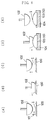
- Fig. 1 shows a basic typical example of a structure of a mold employed by the manufacturing method of the present invention.
- the mold comprises an upper mold 1 and a lower mold 2, by which a cavity is defined for forming plastic products.
- Concave portions 3a, 3b, 3c are provided inside the cavity of the upper mold 1 for forming convex portions of the molded product to project from the surface of the molded product.
- the upper mold 1 and the lower mold 2 are coupled to each other to form the cavity and sealed up as in Fig. 2, and a synthetic resin R is injected into the cavity through an injection port G to fill the cavity.
- a resin which can be subject to injection molding can be adopted as the synthetic resin R, and they are, for example, acetyl cellulose, polycarbonate, polyacryle, polyamide, PES (polyethylene sulfone), or PAS (polyacrylsulfone).
- the synthetic resin R is, for example, a transparent resin material containing a scaly pigment L for permitting the scaly pigment L to be deflected in an orientational direction at the concave portions 3a, 3b, 3c of the upper mold 1.
- Small pieces of mica coated with titanium oxide, or metal flakes, for example, are employed as the scaly pigment L.
- the synthetic resin material R is injected into the cavity through the injection port G as shown in Fig. 2, the synthetic resin material R is subject to a leafing to form a leafing state M1 which is oriented as a whole, and particularly, the flow of the synthetic resin R is locally changed in the concave portions 3a, 3b, 3c.
- Fig. 3 is an enlarged view of a part of the mold showing the oriented state of the scaly pigment L, from which the leafing state M2 where the pigment is deflected is apparent.
- Fig. 4 shows a molded product 10 formed by injection molding using the upper and lower molds 1 and 2 as described above.
- the molded product 10 has concave portions 11a, 11b, 11c protruding from the surface of the molded product 10 corresponding to the concave portions 3a, 3b, 3c of the mold.
- a leafing state is formed inside these convex portions 11a, 11b, 11c in which the pigment is deflected, as described above.
- the leafing state M2 in which the scaly pigment L is deflected appears on cut surfaces 11A, 11B, 11C after these convex portions 11a, 11b, 11c are cut (cutting step).
- the cut surfaces 11A, 11B, 11C have a complicated reflection characteristic which is delicately different from that of other parts depending on the change of the direction of orientation in which the scaly pigment L is deflected.
- the cut surfaces 11A, 11B, 11C are not necessarily flattened after the leafing state M2 is exposed.
- cut surfaces 11A, 11B, 11C are further flattened to the utmost, thereby making it easy to apply correct coloring.
- polishing In this case, they can be flattened by polishing. Barrel polishing or buffing is desirable for such polishing (flattening step).
- the molded product 10 is colored by pressing and sticking dyestuff on the cut surfaces 11A, 11B, 11C thereof (coloring step).
- a printing method using a pad is desirable in this coloring process.
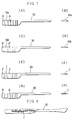
- Figs. 6 (A) to (E) show the printing method in the order of main printing step making use of a pad adaptable for the present invention.
- a predetermined dyestuff I is poured into a concave plate 100, and then extra dyestuff is wiped off with a doctor knife 101 or the like.
- the dyestuff I is applied onto the concave plate 100 in a pattern corresponding to the pattern produced on the cut surfaces in the method of the present invention.
- a pad 102 made of silicon and having elasticity is lowered downwardly on the dyestuff I to press the concave plate 100 as shown in Fig. 6 (B).
- the pad 102 is raised next and then the dyestuff I is transferred to the surface of the pad 102 as shown in Fig. 6 (C).
- the pad 102 to which the dyestuff I is transferred is then pressed at a given pressure on the surface of the material 103 (molded product 10) to be printed as shown in Fig. 6 (D).
- the graphic pattern produced on the surface of the molded product 10, i.e., the printed material 103 can be colored in a desired color tone.
- Hardness of the pad to be adopted is preferable in the range from 40 to 70.
- the molded product must be fixed to and supported by a special reception table for transferring and printing the pattern onto the molded product.
- a reception table 104 having a recessed portion corresponding to the shape of the molded product must be used as this receiving member, wherein the molded product is engaged into the recessed portion of the reception table 104 so as to be fixedly supported by the recessed portion.
- the molded product can be correctly positioned, thereby permitting a color pattern to be accurately transferred onto the graphic pattern already formed on the cut surfaces.
- the molded product is liable to be easily injured since they are made of a plastic material, and consequently, the reception table 104 must be made of a soft resin material, e.g., two liquid curing resin such as putty silicon or putty epoxy.
- molded plastic products producing an excellent color pattern as well as a stereographic pattern can be obtained by adding colors corresponding to the stereographic pattern already appeared on the cut surfaces in the leafing state of the molded product 10.
- the cut surfaces having the stereographic colored pattern thereon are heated for slowly infiltrating the dyestuff under the cut surfaces (infiltrating step).
- a temperature at this time is in the range of 80 to 120 °C in view of infiltration property of the dyestuff. At a temperature of 80 °C or less, the dyestuff is not infiltrated sufficiently and at a temperature of 120 °C or more the surface of the molded product may be deformed.
- Heating time ranges from twenty to seventy minutes, although it is varied depending on the temperature. If the cut surfaces are heated for twenty minutes or less, the dyestuff is infiltrated shallowly to deteriorate the corrosion resistance, whereas if they are heated for seventy minutes or more, the dyestuff is infiltrated and spreads excessively in the lateral direction to cause a blur of the pattern.
- the dyestuff containing binders and the like remaining on the cut surfaces is removed (step of removing the dyestuff or the like).
- This removing process is a preceding step for surely coating the surface in the next step, and concretely, it is executed by barrel polishing or buffing. Solvents may be used for the removal depending on the material.
- the entire surface of the molded product including the cut surfaces is coated with a transparent resin after the binders, the dyestuff and the like are removed from the surface of the molded product (coating step).
- a transparent coating is mainly adopted for such coating so that the colored stereographic pattern produced on the cut surfaces might not be blurred.
- a molded plastic product having the multicolored stereographic pattern can be manufactured.
- Figs. 7 (A) to 7 (H) shows steps for manufacturing the molded products, namely, a temple of eyeglasses.
- the above four steps i.e., the deflecting step, the cutting step, the coloring step, and the infiltrating step are necessary.
- the flattening step executed after the cutting step, the step of removing the dyestuff executed after the infiltrating step, and the coating step executed after the step of removing the dyestuff can be selectively added.
- Multicolored molded plastic products having stereographic patterns of higher quality can be manufactured by adding the above respective steps to the main four steps.
- a transparent nylon resin which is a synthetic resin material R is used as a material of a molded product. Titanium-oxide coated mica ( ⁇ 0.02 mm; a kind of pearl pigment) is used for the scaly pigment L which is blended with the transparent nylon resin.
- the containing ratio of the titanium-oxide-coated mica with respect to the transparent nylon resin is set to be 0.5 weight %.
- a molded plastic product for a frame of eyeglasses is produced by injection molding at a resin temperature of 230°C by using the predetermined mold (see Fig. 1).
- Molded convex portions protruded from the surface of the molded product are cut by using a milling machine.
- the surface is further polished and lustered by barrel polishing in two stages (rough, medium).
- the exposed cut surfaces of the molded product are colored in a pattern corresponding to that of the pattern on the cut surfaces.
- ink I containing disperse dye is poured into the concave plate 100 having a pattern corresponding to that produced on the cut surfaces, and extra ink I is wiped away by a doctor knife 101 as shown in Fig. 9.
- the ink I is stuck to the pad 102, and the pad 102 is pressed on and stuck to the molded product 10 which is fixed to and supported by a reception table 104 so that the ink I is transferred to the molded product 10 (see Fig. 10).
- the ink I was transferred to and printed on the cut surfaces, the ink was baked for 40 minute suitably at a resin temperature of 180°C.
- the ink I is infiltrated under the cut surfaces of the molded product 10.
- the extra ink remaining on the surface of the molded product 10 is removed by barrel polishing after it is baked.
- the surface of the molded product 10 is coated with two-liquid curing type urethane paint.
- the coating was carried out for 2 hours at a temperature of 50°C.
- an excellent stereographic pattern having a littering silky luster can be produced on the cut surfaces of the molded product 10 since the ink contains pearl pigment.
- Acetyl cellulose of a cellulose based resin is employed as a material of a molded product, and aluminum flakes and black pigment are employed as the scaly pigment blended with the acetyl cellulose (a product by the name of "Heat Resistant Black” made by Mitsubishi Material K.K.).
- the containing ratio of the scaly pigment L with respect to the acetyl cellulose is 0.05 weight % for aluminum flakes, and 0.01 weight % for the black pigment.
- a molded plastic product for a frame of eyeglasses is manufactured by injection molding at a resin temperature of 180°C using the mold.
- Molded convex portion protruded from the surface of the molded plastic product are cut by using a milling machine.
- the cut surface is further polished and lustered by barrel polishing in three stages (rough, medium, fine).
- a transparent nylon resin is used as a material of a molded product. Titanium-oxide-coated mica ( ⁇ 0.02 mm; another name is called as pearl pigment) was employed as the scaly pigment L blended with the transparent nylon resin.
- the containing ratio of the titanium-oxide-coated mica with respect to the transparent nylon resin is 0.5 weight %.
- a molded plastic product 10 for a frame of eyeglasses is manufactured by injection molding at a resin temperature of 190°C by using the mold.
- Molded convex portions protruded from the surface of the molded product are cut by using a milling machine.
- the cut surface was printed with transfer ink red containing pigment (Celicole Ink made by Imperial Ink K. K.) in a pad printing method.
- transfer ink red containing pigment Cosmetic Ink made by Imperial Ink K. K.
- cut surface was further printed with transfer ink red blue (Celicole Ink made by Imperial Ink K.K.).
- the ink was baked for 20 minutes at a temperature of 80°C. After this baking, ink binders remaining on the molded product 10 were removed and cleaned using alcohol as a solvent.
- the pattern was printed on a paper with transfening ink red (Celicole Ink made by Imperial Ink K.K.).
- the present invention can be effectively applicable, for example, to other plastic parts of this kind, although in the above embodiments, a manufacturing method of a molded plastic product for the frame of eyeglasses was described in particular.
Landscapes
- Engineering & Computer Science (AREA)
- Mechanical Engineering (AREA)
- Manufacturing & Machinery (AREA)
- Chemical & Material Sciences (AREA)
- Dispersion Chemistry (AREA)
- Casting Or Compression Moulding Of Plastics Or The Like (AREA)
Applications Claiming Priority (2)
| Application Number | Priority Date | Filing Date | Title |
|---|---|---|---|
| JP134360/96 | 1996-04-30 | ||
| JP8134360A JPH09295356A (ja) | 1996-04-30 | 1996-04-30 | 立体グラフィック調模様を有する眼鏡用多色プラスチック部品の製造方法 |
Publications (1)
| Publication Number | Publication Date |
|---|---|
| EP0805019A1 true EP0805019A1 (fr) | 1997-11-05 |
Family
ID=15126558
Family Applications (1)
| Application Number | Title | Priority Date | Filing Date |
|---|---|---|---|
| EP97106640A Withdrawn EP0805019A1 (fr) | 1996-04-30 | 1997-04-22 | Procédé pour la fabrication d'un produit multicoloré moulé avec un motif stéréographique |
Country Status (2)
| Country | Link |
|---|---|
| EP (1) | EP0805019A1 (fr) |
| JP (1) | JPH09295356A (fr) |
Cited By (6)
| Publication number | Priority date | Publication date | Assignee | Title |
|---|---|---|---|---|
| ES2157780A1 (es) * | 1999-04-21 | 2001-08-16 | Roman Fernando Jose Honojosa | Procedimiento para constituir las piezas base para la fabricacion de gafas, instalacion para llevar a cabo dicho procedimiento, y pieza base resultante. |
| ES2161178A1 (es) * | 1999-10-22 | 2001-11-16 | Roman Fernando Jose Hinojosa | Procedimiento perfeccionado para constituir las piezas base para la fabricacion de gafas |
| WO2008101521A1 (fr) * | 2007-02-22 | 2008-08-28 | Manfred Jacob Kunststofftechnik Gmbh | Procédé de production d'un composant en matière plastique imprimé, dispositif pour la mise en oeuvre de ce procédé et composant en matière plastique obtenu selon ce procédé |
| EP1567314B2 (fr) † | 2002-11-09 | 2011-05-25 | Braun GmbH | Corp de brosse à dents |
| US9167890B2 (en) | 2011-02-01 | 2015-10-27 | Colgate-Palmolive Company | Oral care implement having a decorative member and a method of forming the same |
| CN114379125A (zh) * | 2022-01-19 | 2022-04-22 | 东莞市思瑞橡塑制品有限公司 | 一种眼镜装饰件及其制备方法和眼镜装饰件用模具 |
Citations (8)
| Publication number | Priority date | Publication date | Assignee | Title |
|---|---|---|---|---|
| US3288666A (en) * | 1963-04-12 | 1966-11-29 | Celanese Corp | Decorative laminates |
| US4089922A (en) * | 1975-02-07 | 1978-05-16 | Yoshino Kogyosho Co., Ltd. | Molded article having stereoscopic decorative pattern and fabrication process therefor |
| JPS5570048A (en) * | 1978-11-22 | 1980-05-27 | Hitachi Ltd | Method of marking resin sealed semiconductor device |
| US4406662A (en) * | 1982-03-05 | 1983-09-27 | E. I. Du Pont De Nemours And Company | Heat transfer printing on a filled polymethyl methacrylate article |
| US4668239A (en) * | 1982-05-12 | 1987-05-26 | K-T, Inc. | Method of applying a dye image to a plastic member |
| EP0532340A2 (fr) * | 1991-09-13 | 1993-03-17 | HORIKAWA SEISAKUSHO Co., Ltd. | Produit décoratif de résine synthétique et procédé pour sa fabrication |
| US5214022A (en) * | 1990-03-08 | 1993-05-25 | Deutsche Airbus Gmbh | Method for transfer printing an image motif onto a decor film |
| WO1995019266A1 (fr) * | 1994-01-13 | 1995-07-20 | Courtaulds Plc | Impression de dessins optiques sur des articles polymeres |
-
1996
- 1996-04-30 JP JP8134360A patent/JPH09295356A/ja active Pending
-
1997
- 1997-04-22 EP EP97106640A patent/EP0805019A1/fr not_active Withdrawn
Patent Citations (8)
| Publication number | Priority date | Publication date | Assignee | Title |
|---|---|---|---|---|
| US3288666A (en) * | 1963-04-12 | 1966-11-29 | Celanese Corp | Decorative laminates |
| US4089922A (en) * | 1975-02-07 | 1978-05-16 | Yoshino Kogyosho Co., Ltd. | Molded article having stereoscopic decorative pattern and fabrication process therefor |
| JPS5570048A (en) * | 1978-11-22 | 1980-05-27 | Hitachi Ltd | Method of marking resin sealed semiconductor device |
| US4406662A (en) * | 1982-03-05 | 1983-09-27 | E. I. Du Pont De Nemours And Company | Heat transfer printing on a filled polymethyl methacrylate article |
| US4668239A (en) * | 1982-05-12 | 1987-05-26 | K-T, Inc. | Method of applying a dye image to a plastic member |
| US5214022A (en) * | 1990-03-08 | 1993-05-25 | Deutsche Airbus Gmbh | Method for transfer printing an image motif onto a decor film |
| EP0532340A2 (fr) * | 1991-09-13 | 1993-03-17 | HORIKAWA SEISAKUSHO Co., Ltd. | Produit décoratif de résine synthétique et procédé pour sa fabrication |
| WO1995019266A1 (fr) * | 1994-01-13 | 1995-07-20 | Courtaulds Plc | Impression de dessins optiques sur des articles polymeres |
Non-Patent Citations (1)
| Title |
|---|
| PATENT ABSTRACTS OF JAPAN vol. 004, no. 112 (E - 021) 12 August 1980 (1980-08-12) * |
Cited By (9)
| Publication number | Priority date | Publication date | Assignee | Title |
|---|---|---|---|---|
| ES2157780A1 (es) * | 1999-04-21 | 2001-08-16 | Roman Fernando Jose Honojosa | Procedimiento para constituir las piezas base para la fabricacion de gafas, instalacion para llevar a cabo dicho procedimiento, y pieza base resultante. |
| ES2161178A1 (es) * | 1999-10-22 | 2001-11-16 | Roman Fernando Jose Hinojosa | Procedimiento perfeccionado para constituir las piezas base para la fabricacion de gafas |
| EP1567314B2 (fr) † | 2002-11-09 | 2011-05-25 | Braun GmbH | Corp de brosse à dents |
| US20150164209A1 (en) * | 2002-11-09 | 2015-06-18 | Braun Gmbh | Injection molded part |
| US9066577B1 (en) | 2002-11-09 | 2015-06-30 | Braun Gmbh | Injection molded part |
| WO2008101521A1 (fr) * | 2007-02-22 | 2008-08-28 | Manfred Jacob Kunststofftechnik Gmbh | Procédé de production d'un composant en matière plastique imprimé, dispositif pour la mise en oeuvre de ce procédé et composant en matière plastique obtenu selon ce procédé |
| US9167890B2 (en) | 2011-02-01 | 2015-10-27 | Colgate-Palmolive Company | Oral care implement having a decorative member and a method of forming the same |
| CN114379125A (zh) * | 2022-01-19 | 2022-04-22 | 东莞市思瑞橡塑制品有限公司 | 一种眼镜装饰件及其制备方法和眼镜装饰件用模具 |
| CN114379125B (zh) * | 2022-01-19 | 2023-11-17 | 东莞市思瑞橡塑制品有限公司 | 一种眼镜装饰件及其制备方法和眼镜装饰件用模具 |
Also Published As
| Publication number | Publication date |
|---|---|
| JPH09295356A (ja) | 1997-11-18 |
Similar Documents
| Publication | Publication Date | Title |
|---|---|---|
| CN1348551A (zh) | 珠光隐形眼镜片 | |
| EP0311079B1 (fr) | Procédé pour fabriquer des articles moulés à dessin irrégulier | |
| JP2004516524A (ja) | 不透明な虹彩模様をもつコンタクトレンズ | |
| EP0540335A2 (fr) | Plaque de décoration contenant un réseau de diffraction et un motif imprimé | |
| EP0805019A1 (fr) | Procédé pour la fabrication d'un produit multicoloré moulé avec un motif stéréographique | |
| US6099379A (en) | Eye article for taxidermy form | |
| JP2020506095A (ja) | 装飾面を有する成形プラスチック部品の製造方法及び装飾面を有する成形プラスチック部品 | |
| JPS5814312B2 (ja) | 化粧シ−トおよびその製造方法 | |
| EP0639470B1 (fr) | Methode de realisation de motifs colores irreguliers et film de transfert thermique | |
| HK1002933B (en) | Method of forming colored uneven patterns, and thermal transfer foil | |
| KR20040032016A (ko) | 인서트 몰딩용 필름의 제조방법 | |
| JPH0818377B2 (ja) | 眼鏡フレームの合成樹脂化粧部品、およびその製造方法 | |
| KR101470645B1 (ko) | 인서트 가식 성형품의 제조 방법 | |
| KR102033683B1 (ko) | 두께감 및 메탈감을 갖는 고광택 문양 구현이 가능한 데코필름 제조방법 및 그 데코필름 | |
| JP3035175U (ja) | 立体グラフィック調模様を有する眼鏡用多色プラスチック部品 | |
| JP3684276B2 (ja) | ヘアライン目インサートフィルム、ヘアライン目インサート成形品の製造方法 | |
| JPH06106572A (ja) | 二色成形品とその製造方法 | |
| JP4098952B2 (ja) | 時計用文字板及びその製造方法 | |
| JPH07265498A (ja) | 遊技台の装飾部構造 | |
| JP4184773B2 (ja) | 装飾用部材およびその製造方法 | |
| JP4671210B2 (ja) | 部分光輝性成形物とその製造方法 | |
| JPS61172626A (ja) | 光輝性メタリツク加飾印刷を施した金属製容器蓋体等の製造方法 | |
| JP4266049B2 (ja) | 凹凸模様を有する装飾用シートの製造方法 | |
| JPH1044185A (ja) | 成形同時絵付け品とその製造方法 | |
| EP1170150A2 (fr) | Méthode d' impression |
Legal Events
| Date | Code | Title | Description |
|---|---|---|---|
| PUAI | Public reference made under article 153(3) epc to a published international application that has entered the european phase |
Free format text: ORIGINAL CODE: 0009012 |
|
| 17P | Request for examination filed |
Effective date: 19970903 |
|
| AK | Designated contracting states |
Kind code of ref document: A1 Designated state(s): DE FR GB IT |
|
| 17Q | First examination report despatched |
Effective date: 19990331 |
|
| GRAG | Despatch of communication of intention to grant |
Free format text: ORIGINAL CODE: EPIDOS AGRA |
|
| GRAG | Despatch of communication of intention to grant |
Free format text: ORIGINAL CODE: EPIDOS AGRA |
|
| GRAH | Despatch of communication of intention to grant a patent |
Free format text: ORIGINAL CODE: EPIDOS IGRA |
|
| STAA | Information on the status of an ep patent application or granted ep patent |
Free format text: STATUS: THE APPLICATION IS DEEMED TO BE WITHDRAWN |
|
| 18D | Application deemed to be withdrawn |
Effective date: 20011002 |