EP0806259A1 - Dispositif de percage de l'ame d'un profile d'acier - Google Patents
Dispositif de percage de l'ame d'un profile d'acier Download PDFInfo
- Publication number
- EP0806259A1 EP0806259A1 EP96937516A EP96937516A EP0806259A1 EP 0806259 A1 EP0806259 A1 EP 0806259A1 EP 96937516 A EP96937516 A EP 96937516A EP 96937516 A EP96937516 A EP 96937516A EP 0806259 A1 EP0806259 A1 EP 0806259A1
- Authority
- EP
- European Patent Office
- Prior art keywords
- section
- boring
- frame
- lever
- jig
- Prior art date
- Legal status (The legal status is an assumption and is not a legal conclusion. Google has not performed a legal analysis and makes no representation as to the accuracy of the status listed.)
- Withdrawn
Links
Images



Classifications
-
- E—FIXED CONSTRUCTIONS
- E01—CONSTRUCTION OF ROADS, RAILWAYS, OR BRIDGES
- E01B—PERMANENT WAY; PERMANENT-WAY TOOLS; MACHINES FOR MAKING RAILWAYS OF ALL KINDS
- E01B31/00—Working rails, sleepers, baseplates, or the like, in or on the line; Machines, tools, or auxiliary devices specially designed therefor
- E01B31/02—Working rail or other metal track components on the spot
- E01B31/06—Making holes, e.g. by drilling, punching, flame-cutting
-
- B—PERFORMING OPERATIONS; TRANSPORTING
- B23—MACHINE TOOLS; METAL-WORKING NOT OTHERWISE PROVIDED FOR
- B23B—TURNING; BORING
- B23B41/00—Boring or drilling machines or devices specially adapted for particular work; Accessories specially adapted therefor
-
- B—PERFORMING OPERATIONS; TRANSPORTING
- B23—MACHINE TOOLS; METAL-WORKING NOT OTHERWISE PROVIDED FOR
- B23B—TURNING; BORING
- B23B41/00—Boring or drilling machines or devices specially adapted for particular work; Accessories specially adapted therefor
- B23B41/003—Boring or drilling machines or devices specially adapted for particular work; Accessories specially adapted therefor for drilling elongated pieces, e.g. beams
- B23B41/006—Boring or drilling machines or devices specially adapted for particular work; Accessories specially adapted therefor for drilling elongated pieces, e.g. beams the machining device being moved along a fixed workpiece
-
- Y—GENERAL TAGGING OF NEW TECHNOLOGICAL DEVELOPMENTS; GENERAL TAGGING OF CROSS-SECTIONAL TECHNOLOGIES SPANNING OVER SEVERAL SECTIONS OF THE IPC; TECHNICAL SUBJECTS COVERED BY FORMER USPC CROSS-REFERENCE ART COLLECTIONS [XRACs] AND DIGESTS
- Y10—TECHNICAL SUBJECTS COVERED BY FORMER USPC
- Y10T—TECHNICAL SUBJECTS COVERED BY FORMER US CLASSIFICATION
- Y10T408/00—Cutting by use of rotating axially moving tool
- Y10T408/55—Cutting by use of rotating axially moving tool with work-engaging structure other than Tool or tool-support
- Y10T408/561—Having tool-opposing, work-engaging surface
- Y10T408/5623—Having tool-opposing, work-engaging surface with presser foot
-
- Y—GENERAL TAGGING OF NEW TECHNOLOGICAL DEVELOPMENTS; GENERAL TAGGING OF CROSS-SECTIONAL TECHNOLOGIES SPANNING OVER SEVERAL SECTIONS OF THE IPC; TECHNICAL SUBJECTS COVERED BY FORMER USPC CROSS-REFERENCE ART COLLECTIONS [XRACs] AND DIGESTS
- Y10—TECHNICAL SUBJECTS COVERED BY FORMER USPC
- Y10T—TECHNICAL SUBJECTS COVERED BY FORMER US CLASSIFICATION
- Y10T408/00—Cutting by use of rotating axially moving tool
- Y10T408/55—Cutting by use of rotating axially moving tool with work-engaging structure other than Tool or tool-support
- Y10T408/563—Work-gripping clamp
Definitions
- the present invention relates to a portable electric drill type boring apparatus for boring webs of steel sections such as rails, H sections, I sections and channels.
- Figure 8 illustarates a boring apparatus 101 according to a first prior art.
- This apparatus 101 is a portable electric drill having a magnetic fixing device 100. Procedures of drilling a web 103 of an H section 102 using this boring apparatus 101 will be described referring to Figure 8.
- the H section 102 is placed such that the web 103 thereof may be substantially horizontal, and the fixing device 100 is disposed at a predetermined position on the surface of the web 103.
- the fixing device 100 is fixed on the web 103 by the magnetic force of a magnet.
- the boring apparatus 101 is descended to drill downward the web 103 at the predetermined position. Drilling of a web of a channel can be performed in the same manner as in the drilling of the H section.
- a special section boring apparatus is also known as a second prior art. This boring apparatus drills both flanges 104 and a web 103 using separate drills respectively.
- Japanese Unexamined Patent Publication No. Hei 7-9222 descloses a boring apparatus as a third prior art.
- This boring apparatus described therein has a pair of clamping plates for clamping a pair of side walls of a channel and a drill which is disposed to be movable toward a web present between the thus clamped side walls of the channel. Accordingly, the web can be drilled by operating the drill with the channel being clamped by the clamping plates.
- a section must be placed such that the face to be drilled or the web thereof may assume a horizontal posture and then the fixing device 100 is mounted on the horizontal face, because the boring apparatus 101 is merely magnetically fixed on the web 103, and if the web 103 is not maintained horizontally, the apparatus 101 readily slips out of position.
- this boring apparatus 101 involves a problem that positioning of the drill at a predetermined point requires intricate procedures since it employs a large and heavy magnet, and thus the apparatus has poor drilling efficiency.
- the special boring apparatus according to the second prior art is generally big and heavy and is a stationary equipment, so that a section must be carried to the apparatus.
- the section is placed once on a work-table of the apparatus and then set at a drilling position. Accordingly, it takes time and labor to carry sections to the special boring apparatus and also to load and unload the section to and from the work-table.
- a section such as a channel and an H section is clamped by clamping plates before it is subjected to drilling. Accordingly, the section placed on the floor cannot be clamped as such, so that webs of sections placed on the floor cannot be drilled, disadvantageously.
- the section web boring apparatus has a boring device for boring a web of a clamped section in the state where the axis of the boring device is perpendicular to the web; a frame for supporting the boring device; and a clamping mechanism for claming the section from each side in the direction substantially parallel to the rotation axis of the boring device.
- a section placed on the floor can be clamped by the clamping mechanism, and an edge of the boring device can bore the web of the thus clamped section.
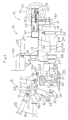
- Section web boring apparatus 10 First, schematic constitution of a section web boring apparatus 10 will be described. Parts constituting the section web boring apparatus 10 are made of materials having sufficient strength such as iron and stainless steel. In this embodiment, the left side and the right side in Figure 3 are appreciated to be the front side and the rear side, respectively.
- the boring apparatus 10 has a frame consisting of a pair of arm plates 11 connected and fixed to each other.
- a pair of guide rails 12 are fixed to the proximal end portions of the arm plates 11 respectively.
- a table 13 is slidably attached to the guide rails 12.
- a grip 26 is fixed on the table 13 on the center line thereof via a bracket 25.
- a boring device 24 is located under the table 13.
- a clamping device 18 for clamping a section 19 is provided at the distal end portions of the arm plates 11.
- a moving mechanism 14 for advancing and retracting the boring device 24 is provided on the rear side of the table 13.
- the pair of arm plates 11 are connected to each other at the middle parts thereof by a support shaft 27.
- the lower half of each arm plate 11 locates on the rear side of the section 19; whereas the upper half overhangs the section 19 to extend to the front side of the section 19.
- Jigs 21 are attached to the lower parts of the arm plates 11 by screws 70.
- the screws 70 are inserted to screw holes 20 of the arm plates 11 via the jigs 21, and the jigs 21 are fastened to the arm plates 11 by tightening the screws 70.
- the jig 21, so as to hold the section 19, has a shape fitting to the profile of the section 19.
- the lower part and the upper part of each jig 21 are designed to be abutted against the upper face of the lower flange 22 and the lower face of the head 23 of the section 19, respectively.
- the front ends of the guide rails 12 are attached via metal fittings 12a to the proximal ends of the arm plates 11 respectively.
- the pair of guide rails 12 are arranged to be parallel to each other and to be horizontal in the state where the boring apparatus 10 is set against the section 19.
- This device 18 is provided with a toggle latch mechanism.
- the clamping device 18 consists of an operating lever 15 pivotally fixed to the support shaft 27, a working lever 16 pivotally connected via pintles 31 to the arm plates 11, and an intermediate link 17 pivotally attached to the working lever 16 and the operating lever 15.
- the operating lever 15 has a substantially U-shaped proximal end portion 15a which is pivotally attached to each end of the support shaft 27 on the outer sides of the arm plates 11.
- the distal end portion of the operating lever 15 constitutes a grip 28.
- the working lever 16 has a pair of arm plates 29 and a connecting plate 30 which connects the arm plates 29 to each other at the lower parts thereof.
- a pintle 31 is formed to protrude outward from the upper end portion of each arm plate 29.
- a through hole 32 is formed at the center of the connecting plate 30.
- Bolts 33 are screwed into each end portion of the connecting plate 30.
- a pressing plate 34 to be abutted against the web of the section 19 is provided at the tip of each bolt 33. The advancement quantity of the pressing plates 34 can be adjusted by turning the bolts 33.
- the intermediate link 17 has a pair of link plates 35 and an operating shaft 37 provided at the proximal end portions of these link plates 35 to connect them to each other.
- a pair of working shafts 36 protrude outward from the distal end portions of these link plates 35.
- the intermediate link 17 is pivotally attached to the operating lever 15 by the operating shaft 37 and to the working lever 16 by the working shaft 36.
- the axis of the working shaft 36 ascends relative to a line 49 drawn to connect the axis of the support shaft 27 and the axis of the operating shaft 37 as the operating lever 15 is turned. If the axis of the working shaft 36 ascended beyond the dead point on the line 49, the operating lever 15 is prevented from turning in the opposite direction.
- the pressing plates 34 are adapted to be pressed against the section 19 so that clamping by the pressure plates 34 may not be easily released.
- a pair of stoppers 38 are provided on the inner faces of the operating lever 15 at the proximal end portion 15a. These stoppers 38 are abutted against the working lever 16 when the operating lever 15 is turned clockwise to restrict clockwise turning of the working lever 16. Meanwhile, another pair of stoppers 39 are provided on the outer surfaces of the intermediate link 17. These stoppers 39 are abutted against the working lever 16 when the operating lever 15 is turned counterclockwise to restrict counterclockwise turning of the working lever 15.
- the boring apparatus 10 can be carried to be set against the section 19 as described below.
- the working lever 16 When the working lever 16 is abutted against the stoppers 38 as the operating lever 15 is turned, the working lever 16 is restricted from turning any further. In this state, the boring apparatus 10 can be lifted with the handles 26, 28 being gripped by the operator.
- the boring apparatus 10 thus lifted is carried as such over the section 19, and then the apparatus 10 is descended such that the section 19 may locate between the jigs 21 and the pressing plates 34.
- the grip 28 is pulled down.
- the operating lever 15 is turned counterclockwise on the support shaft 27, and the working lever 16 is turned counterclockwise together with the intermediate link 17.
- the stoppers 39 are abutted against the working lever 16 and simultaneously the pressing plates 34 are pressed against the section 19.
- the axis of the working shaft 36 ascends beyond the line 49.
- the section 19 is securely clamped between the pressing plates 34 and the jigs 21.
- the table moving mechanism 14 contains a handle 46 disposed on the rear side of the table 13, a main shaft 41 to which rotation of the handle 46 is transmitted, and a bracket 42 which interlocks with the rotation of the main shaft 41.
- the handle 46 is rotatably attached to an auxiliary case 47 mounted on the rear end portion of the table 13.
- a first bevel gear 44 is attached to that end portion of a rotary shaft 45 of the handle 46 which protrudes into the table 13.
- the main shaft 41 is disposed in the auxiliary case 47.
- the front end portion of the main shaft 41 is nondislocatably and rotatably supported in a fitting hole 48 of a connecting block 40 fixed on the table 13.
- a second bevel gear 43 is attached to the rear end portion of the main shaft 41 and is meshed with the first bevel gear 44.
- a thread groove 41a is formed on the circumference of the main shaft 41.
- a fitting hole 74 having a thread groove 42a is defined at the upper end portion of the bracket 42, and the main shaft 41 is inserted to this fitting hole 74.
- the thread groove 42a formed on the bracket 42 is meshed with the thread groove 41a of the main shaft 41.
- the lower end portion of the bracket 42 is secured to the rear end portion of the guide rails 12.
- the boring device 24 is attached to the lower surface of the table 13 by holders 54.
- the boring device 24 has a motor 55 and a cutter 57 having a centering pin.
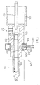
- the cutter 57 having a centering pin consists, as shown in Figure 4, of a holder 61, a cup-like edge 63 attached to the front end of the holder 61, and a centering pin 67 provided in the edge 63.
- the centering pin 67 is disposed on the axis of the edge 63.
- a passage 85 is defined in the holder 61 to open to the front end side.
- a coil spring 69 is disposed in the passage 85.
- the centering pin 67 has a flange 86 at the inner end thereof.
- the front end opening of the passage 85 is closed by a valve (not shown) housed in the flange 86 in the state where the tip of the centering pin 67 is not abutted against the section 19.
- the valve opens the front end opening of the passage 85.
- a communication hole 62 is formed to communicate to the passage 85 and to the outer surface of the holder 61.
- a lubrication ring 58 is provided on the circumference of the holder 61.
- the lubrication ring 58 has an annular form and is designed to be turned relative to the holder 61.
- Sealants 64 made of a rubber, a resin or the like are applied along the inner circumference of the lubrication ring 58.
- the lubrication ring 58 contains a through hole 66 which communicates to a lubricating oil pipe 59.
- the through hole 66 communicates to the communicating hole 62 of the holder 61.
- the lubrication ring 58 is connected via the lubricating oil pipe 59 to a cutting lubricant tank 60 shown in Figure 1.
- a cutting lubricant is stored in the tank 60.
- the cutting lubricant supplied from the cutting lubricant tank 60 passes through the lubricating oil pipe 59 to enter the lubrication ring 58 and further flows through the communicating hole 62 to the passage 85.
- the passage 85 assuming the closed state is opened to allow the cutting lubricant present in the passage 85 to flow toward the centering pin 67.
- the tip of the centering pin 67 is pressed against the center of a portion of the section web to be bored, and the cutting lubricant is supplied from the passage 85 into the edge 63 to effect cooling of the edge 63 and washing of the portion to be bored.
- the centering pin 67 is projected again by the urging force of the coil spring 69 to thrust off cutting chips thus formed.
- the thus thrust off chips pass through the through hole 32 defined at the center of the connecting plate 30 to impinge upon a cover 70 and drop.
- the handle 46 is turned in the opposite direction to pull the edge 63 apart from the section 19, and then the grip 28 is pulled up to allow the working link 16 to be spaced from the section 19.
- the operator grips the grips 26, 28 and lifts the boring apparatus 10, and thus the boring apparatus 10 can be released from the section 19.
- a pointing device 71 will be hereinafter described.
- a pointing device 71 is disposed between the arm plates 11, as shown in Figure 5.
- the pointing device 71 has a pivotal shaft 73 inserted to through holes 72 defined through the arm plates 11, a pointer 77 attached to the rotary shaft 73, and a lever 78 attached to one end of the rotary shaft 73.
- the pointer 77 is fixed to the rotary shaft 73 by thumbscrews 75 and nuts 76.
- a mark 79 is drawn on the upper end face of the section 19 straight above the position to be bored.
- the lever 78 of the pointing device 71 is turned to locate the pointer 77 on the upper end face of the section 19.
- the boring apparatus 10 is slid in the longitudinal direction of the section 19 to align the pointer 77 with the mark 79.
- the grip 28 is pulled down when the boring apparatus 10 is moved to a position where the pointer 77 points the mark 79, and the boring apparatus 10 can be fixed to a predetermined boring position.
- the boring device 24 is rotationally driven and the handle 46 is brought closer to the web of the section 19, the web of the section 19 can be bored by the edge 63 of the boring device 24 attached to the table 13.
- the present invention can be realized according to other embodiments.
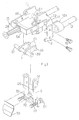
- Figure 6 shows another embodiment of the present invention which employs jigs 81 which are different from those employed in the foregoing embodiment.
- the jigs 81 are engaged with the upper flange 82 of an H section 79a.
- a drill 56 is employed as the boring device.
- the boring position can be changed by adjusting the fitting position of the jigs 81 in the vertical direction to change the distance 83.
- the boring apparatus of the present invention can be employed for boring not only H sections but also other sections (e.g., I sections and channels), and the shape of the jigs can be changed as necessary.
- the moving mechanism 14 employing the bevel gear 44 may be replaced with a rack and pinion type moving mechanism 53, for example, as shown in Figure 7.
- a pinion 51 is attached to the drive shaft 45
- a rack 52 is attached to the upper end of the bracket 42 so as to be engaged with the pinion 51.
- the former moving mechanism 14 is stronger than the latter mechanism 53 because the former advances via a screw.
- the latter mechanism 53 is greater than the former mechanism 14.
Landscapes
- Engineering & Computer Science (AREA)
- Mechanical Engineering (AREA)
- Architecture (AREA)
- Civil Engineering (AREA)
- Structural Engineering (AREA)
- Drilling And Boring (AREA)
Applications Claiming Priority (3)
| Application Number | Priority Date | Filing Date | Title |
|---|---|---|---|
| JP317516/95 | 1995-11-09 | ||
| JP31751695A JP3375475B2 (ja) | 1995-11-09 | 1995-11-09 | 形鋼ウェブの穿孔装置 |
| PCT/JP1996/003255 WO1997017156A1 (fr) | 1995-11-09 | 1996-11-07 | Dispositif de percage de l'ame d'un profile d'acier |
Publications (2)
| Publication Number | Publication Date |
|---|---|
| EP0806259A1 true EP0806259A1 (fr) | 1997-11-12 |
| EP0806259A4 EP0806259A4 (fr) | 2000-07-05 |
Family
ID=18089116
Family Applications (1)
| Application Number | Title | Priority Date | Filing Date |
|---|---|---|---|
| EP96937516A Withdrawn EP0806259A4 (fr) | 1995-11-09 | 1996-11-07 | Dispositif de percage de l'ame d'un profile d'acier |
Country Status (7)
| Country | Link |
|---|---|
| US (1) | US5938378A (fr) |
| EP (1) | EP0806259A4 (fr) |
| JP (1) | JP3375475B2 (fr) |
| CN (1) | CN1065462C (fr) |
| AU (1) | AU698462B2 (fr) |
| CA (1) | CA2209732C (fr) |
| WO (1) | WO1997017156A1 (fr) |
Cited By (1)
| Publication number | Priority date | Publication date | Assignee | Title |
|---|---|---|---|---|
| WO2002030602A1 (fr) * | 2000-10-13 | 2002-04-18 | Kohori Tekkou Kabushiki Kaisha | Machine a percer les rails |
Families Citing this family (16)
| Publication number | Priority date | Publication date | Assignee | Title |
|---|---|---|---|---|
| JP4971249B2 (ja) * | 2008-05-28 | 2012-07-11 | 大見工業株式会社 | 磁力固定式レール穿孔機 |
| US8491235B2 (en) | 2009-07-30 | 2013-07-23 | Omi Kogyo Co., Ltd. | Rail drilling machine |
| US8807885B2 (en) * | 2010-10-07 | 2014-08-19 | General Electric Company | Method and apparatus for machining a shroud block |
| CN102423811B (zh) * | 2011-06-29 | 2014-01-22 | 天津汽车模具股份有限公司 | 一种用于夹持电钻或风动气钻的磁力架 |
| US9434014B1 (en) * | 2013-10-18 | 2016-09-06 | Bnsf Railway Company | Field-portable hole broaching machines and methods for using the same |
| CN104353860B (zh) * | 2014-11-12 | 2016-11-09 | 汝州郑铁三佳道岔有限公司 | 一种钢轨用钻孔装置 |
| CN104308219B (zh) * | 2014-11-12 | 2016-04-13 | 汝州郑铁三佳道岔有限公司 | 一种钢轨用的钻孔装置 |
| USD863102S1 (en) | 2015-09-29 | 2019-10-15 | Hougen Manufacturing, Inc. | Rail shoe assembly and components thereof |
| US9833842B2 (en) | 2015-09-29 | 2017-12-05 | Hougen Manufacturing, Inc. | Rail shoe assembly |
| CN105945328B (zh) * | 2016-07-11 | 2019-01-15 | 毛湘武 | 气动道轨钻孔器 |
| CN106638186B (zh) * | 2016-12-28 | 2018-05-15 | 周海兵 | 钻机定位固定装置 |
| US11344961B2 (en) | 2018-12-12 | 2022-05-31 | Black & Decker Inc. | Pipe threading or cutting device |
| CN111843498B (zh) * | 2020-08-04 | 2024-09-03 | 国网福建省电力有限公司 | 一种铜排母线的切割打孔装置 |
| CN114592387B (zh) * | 2022-03-04 | 2025-12-05 | 中国铁建高新装备股份有限公司 | 一种无砟轨道承轨台铣磨车 |
| KR102726041B1 (ko) * | 2024-06-17 | 2024-11-05 | 주식회사 코시스 | 에이치빔 클램핑장치 |
| CN121104164B (zh) * | 2025-11-17 | 2026-02-10 | 襄鼎汽车有限公司 | 一种洒水车刹车盘加工的钻孔装置 |
Family Cites Families (14)
| Publication number | Priority date | Publication date | Assignee | Title |
|---|---|---|---|---|
| US2599696A (en) * | 1952-06-10 | Drilling mechanism | ||
| US990115A (en) * | 1909-05-25 | 1911-04-18 | Charles J Coulter | Combination rail-clamp and machine-tool. |
| US1034288A (en) * | 1910-02-21 | 1912-07-30 | Duff Mfg Co | Clamp for drills and the like. |
| US981791A (en) * | 1910-02-21 | 1911-01-17 | Charles H Oslund | Drill. |
| US1016477A (en) * | 1910-03-07 | 1912-02-06 | Charles J Coulter | Combined rail drill and clamp. |
| US1175556A (en) * | 1911-10-24 | 1916-03-14 | Buda Co | Drilling apparatus. |
| US2201032A (en) * | 1933-04-12 | 1940-05-14 | Matthew H Loughridge | Railway rail drilling machine |
| US2113723A (en) * | 1934-01-06 | 1938-04-12 | Edward A Everett | Drilling machine |
| US2203415A (en) * | 1936-05-07 | 1940-06-04 | Railroad Accessories Corp | Rail drilling machine |
| US4261673A (en) * | 1979-04-05 | 1981-04-14 | Hougen Everett D | Magnetic base drill |
| JPS5969841U (ja) * | 1982-10-30 | 1984-05-11 | 三菱重工業株式会社 | 鋼材加工装置の装着装置 |
| US4932814A (en) * | 1989-07-24 | 1990-06-12 | York Ronald A | Portable line boring machine |
| US5061126A (en) * | 1990-05-04 | 1991-10-29 | Rule Industries | Hole saw and mandrel assembly |
| JPH0762321B2 (ja) * | 1992-06-15 | 1995-07-05 | 株式会社山崎歯車製作所 | 鉄道レール穿孔機 |
-
1995
- 1995-11-09 JP JP31751695A patent/JP3375475B2/ja not_active Expired - Lifetime
-
1996
- 1996-11-07 WO PCT/JP1996/003255 patent/WO1997017156A1/fr not_active Ceased
- 1996-11-07 EP EP96937516A patent/EP0806259A4/fr not_active Withdrawn
- 1996-11-07 CA CA002209732A patent/CA2209732C/fr not_active Expired - Fee Related
- 1996-11-07 CN CN96191482A patent/CN1065462C/zh not_active Expired - Lifetime
- 1996-11-07 AU AU75059/96A patent/AU698462B2/en not_active Ceased
- 1996-11-07 US US08/860,933 patent/US5938378A/en not_active Expired - Fee Related
Non-Patent Citations (2)
| Title |
|---|
| No further relevant documents disclosed * |
| See also references of WO9717156A1 * |
Cited By (1)
| Publication number | Priority date | Publication date | Assignee | Title |
|---|---|---|---|---|
| WO2002030602A1 (fr) * | 2000-10-13 | 2002-04-18 | Kohori Tekkou Kabushiki Kaisha | Machine a percer les rails |
Also Published As
| Publication number | Publication date |
|---|---|
| CA2209732A1 (fr) | 1997-05-15 |
| CN1168116A (zh) | 1997-12-17 |
| AU7505996A (en) | 1997-05-29 |
| EP0806259A4 (fr) | 2000-07-05 |
| WO1997017156A1 (fr) | 1997-05-15 |
| CA2209732C (fr) | 2001-12-11 |
| JP3375475B2 (ja) | 2003-02-10 |
| AU698462B2 (en) | 1998-10-29 |
| US5938378A (en) | 1999-08-17 |
| CN1065462C (zh) | 2001-05-09 |
| JPH09131607A (ja) | 1997-05-20 |
Similar Documents
| Publication | Publication Date | Title |
|---|---|---|
| CA2209732C (fr) | Dispositif de percage de l'ame d'un profile d'acier | |
| US8052358B2 (en) | Pocket hole jig system | |
| US7976252B2 (en) | Pocket hole jig tool system | |
| US5542796A (en) | Robotic drill clamp | |
| DE102005043000B4 (de) | Angetriebenes Werkzeug mit Ausrichtführung und Standbohrmaschine mit Ausrichtführung | |
| US4027992A (en) | Boring tool guide device | |
| US20070280797A1 (en) | Pocket Hole Jig Tool System | |
| WO2019175024A1 (fr) | Système de préhension et de positionnement servant au transport d'un dispositif de serrage entre différentes positions | |
| US4679969A (en) | Positive feed drill clamp system | |
| US4669926A (en) | Drill guide apparatus and method | |
| US7226253B2 (en) | Clamping mechanism | |
| CA1131948B (fr) | Chasse-copeaux de percage et (ou) de taraudage | |
| US4167362A (en) | Multiple tool driving turret attachment | |
| US5224682A (en) | Drill holding mechanism | |
| GB2123338A (en) | Apparatus and method for cutting a mortice | |
| US4105361A (en) | Machine tool having quill control means | |
| GB2103540A (en) | A jig to enable a lock-receiving mortise or other slot or hole to be cut in a face of a workpiece | |
| US4417376A (en) | Adjustable cylinder head holder | |
| CN217291290U (zh) | 一种钳头拉杆铣扁钻孔装置 | |
| CN106334812B (zh) | 一种台式钻床 | |
| GB1571778A (en) | Process and machine tool for drilling workpieces | |
| CN222001908U (zh) | 一种灵活的盲孔打孔装置 | |
| JPS60210330A (ja) | 管の側部に穴を形成する装置 | |
| US20250282028A1 (en) | Qucik multi-functional bench vise | |
| CN217912874U (zh) | 一种新的排刀机床副主轴 |
Legal Events
| Date | Code | Title | Description |
|---|---|---|---|
| PUAI | Public reference made under article 153(3) epc to a published international application that has entered the european phase |
Free format text: ORIGINAL CODE: 0009012 |
|
| AK | Designated contracting states |
Kind code of ref document: A1 Designated state(s): DE FR GB SE |
|
| 17P | Request for examination filed |
Effective date: 19971106 |
|
| A4 | Supplementary search report drawn up and despatched |
Effective date: 20000519 |
|
| AK | Designated contracting states |
Kind code of ref document: A4 Designated state(s): DE FR GB SE |
|
| RIC1 | Information provided on ipc code assigned before grant |
Free format text: 7B 23Q 9/00 A, 7B 23B 41/00 B |
|
| 17Q | First examination report despatched |
Effective date: 20020410 |
|
| GRAH | Despatch of communication of intention to grant a patent |
Free format text: ORIGINAL CODE: EPIDOS IGRA |
|
| RIN1 | Information on inventor provided before grant (corrected) |
Inventor name: ISHIKAWA, TARO Inventor name: URASHIMA, CHIKAYUKI Inventor name: OMI, SHOHEI |
|
| STAA | Information on the status of an ep patent application or granted ep patent |
Free format text: STATUS: THE APPLICATION IS DEEMED TO BE WITHDRAWN |
|
| 18D | Application deemed to be withdrawn |
Effective date: 20030402 |