EP0806294A2 - Procédé et dispositif pour le réglage du registre circonférentiel dans une presse rotative comprenant un cylindre porte-cliché muni d'un manchon porte-cliché - Google Patents
Procédé et dispositif pour le réglage du registre circonférentiel dans une presse rotative comprenant un cylindre porte-cliché muni d'un manchon porte-cliché Download PDFInfo
- Publication number
- EP0806294A2 EP0806294A2 EP97107129A EP97107129A EP0806294A2 EP 0806294 A2 EP0806294 A2 EP 0806294A2 EP 97107129 A EP97107129 A EP 97107129A EP 97107129 A EP97107129 A EP 97107129A EP 0806294 A2 EP0806294 A2 EP 0806294A2
- Authority
- EP
- European Patent Office
- Prior art keywords
- speed
- plate
- sleeve
- detector
- printing
- Prior art date
- Legal status (The legal status is an assumption and is not a legal conclusion. Google has not performed a legal analysis and makes no representation as to the accuracy of the status listed.)
- Granted
Links
Images
Classifications
-
- B—PERFORMING OPERATIONS; TRANSPORTING
- B41—PRINTING; LINING MACHINES; TYPEWRITERS; STAMPS
- B41F—PRINTING MACHINES OR PRESSES
- B41F13/00—Common details of rotary presses or machines
- B41F13/08—Cylinders
- B41F13/10—Forme cylinders
- B41F13/12—Registering devices
- B41F13/14—Registering devices with means for displacing the cylinders
-
- B—PERFORMING OPERATIONS; TRANSPORTING
- B41—PRINTING; LINING MACHINES; TYPEWRITERS; STAMPS
- B41F—PRINTING MACHINES OR PRESSES
- B41F13/00—Common details of rotary presses or machines
Definitions
- the present invention relates to a method and a device according to the preamble of claims 1 and 11.
- Printing presses include mechanisms for adjusting the circumferential register of one cylinder relative to another cylinder of the printing press.
- roller rotary printing machines such adjustments are usually made on a plate cylinder to adjust the position of the plate cylinder relative to the associated blanket cylinder in the circumferential direction, the blanket cylinder z. B. is driven via a common drive shaft by the motor of the main drive of the printing press.
- This adjustment in the circumferential direction ensures exact registration of the printed images printed on both sides of the web in the surface and back printing machines printing from blanket to blanket.
- multicolor printing machines such an adjustment of the circumferential register ensures that the printed images are printed with a first color in one printing unit and with a second color in another printing unit.
- the circumferential register setting of each plate cylinder is carried out by means of a helical toothing or a helical gear which is axially movable on the pivot pin of the plate cylinder.
- a helical toothing or a helical gear which is axially movable on the pivot pin of the plate cylinder.
- Such a device is e.g. For example, see U.S. Patent No. 4,709,634, the entire contents of which are incorporated herein by reference.
- the device of US Pat. 4,709,634 further a side register adjustment of the plate cylinder.
- the circumferential register can therefore only be set within a limited range.
- continuous printing plates in the form of sleeves are used, which are applied to the plate cylinder through an opening formed in one side wall of the printing unit housing, the plate cylinder being freely floating or floating in the other side wall of the housing.
- the sleeve-shaped printing plates tend to migrate on the plate cylinder body when the printing press is in operation.
- a printing press in which sleeve-shaped printing plates are used is e.g. For example, see U.S. Patent No. 4,913,048, the entire contents of which are incorporated herein by reference.
- the migration of the sleeve-shaped printing plates on the plate cylinder body often causes register errors in the respective printing unit. Attempts have therefore been made to eliminate the migration of the sleeve-shaped printing plates by z. B. by pinning or otherwise fixing on the respective plate cylinder body. Since the sleeve-shaped printing plates are usually made of lightweight conventional plate material, such as. B. aluminum, there is a risk that they break or become cracked by being fixed by pins on the plate cylinder body, since the material is not strong enough to withstand the forces that arise during the rotation of the printing plate on the plate cylinder body.
- a speed difference between the speed of the sleeve-shaped printing plate and the speed of the printing press is determined and the speed of the plate cylinder body carrying the sleeve-shaped printing plate is changed in such a way that the speed difference is reduced.
- the speed of the sleeve-shaped printing plate is advantageously carried out by detecting marks formed on the sleeve-shaped printing plate, for example register marks, the detection of the register marks on the sleeve-shaped printing plate preferably taking place optically.
- the speed of the sleeve-shaped printing plate is carried out indirectly by measuring a time difference between two successive detections of a register mark.
- the speed of the printing press is preferably determined by an angle encoder or angle encoder, which can be connected, for example, to a blanket cylinder assigned to the plate cylinder.
- it can also be provided to determine the speed of the printing press by detection of register marks which are formed on the body of a blanket cylinder assigned to the plate cylinder, the detection of the register marks on the body of the blanket cylinder advantageously taking place optically and e.g. B. indirectly by measuring a time difference between two successive detections of the register mark on the body of the blanket cylinder.
- the speed of the sleeve-shaped pressure plate can be achieved by differentiating a measured position signal.
- the invention also has a device for setting a circumferential register in a web-fed rotary printing press with a sleeve-shaped one Printing plate on a plate cylinder body-carrying plate cylinder, a first detector for detecting the speed of the sleeve-shaped printing plate, a second detector for detecting the speed of the printing press and a speed control device which determines the speed of the plate-shaped cylinder body carrying the sleeve-shaped printing plate as a function of the speed difference between the through the first detector and controls the second detector of detected speeds such that the speed difference is reduced or minimized.
- the first detector can be, for example, an optical detector which detects a mark arranged on the sleeve-shaped printing plate and, for example, indirectly determines the speed of the sleeve-shaped printing plate by measuring the time difference between two successive detections of the mark.
- the second detector is an angle encoder or angle encoder, which is connected to the body of a blanket cylinder assigned to the plate cylinder.
- the second detector can be a detector which detects marks formed on a blanket cylinder assigned to the plate cylinder, the marks on the blanket cylinder advantageously being able to be optically scanned and the second detector measuring the speed of the printing press, for example indirectly, by measuring a time difference determined between two successive detections of the marks on the blanket cylinder.
- the speed control device comprises a speed-adjustable adjustment gear connected to the plate cylinder.
- the speed control device has individual drives which drive the plate cylinder and / or the associated blanket cylinder separately.
- the method according to the invention and the device according to the invention have the advantage that the setting of the circumferential register can be carried out continuously during the operation of the printing press. It is a further advantage of the present invention that the setting of the circumferential register is not limited to a certain angular range. In addition, the circumferential register setting according to the invention is carried out automatically and does not require any additional actions by the operator.
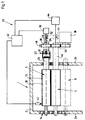
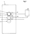
- the printing unit 1 shown in Fig. 1 comprises a housing 2, in which a blanket cylinder 4 and an associated plate cylinder 6 are rotatably received with their pivot pins in respective bearings.
- a further cylinder 8 can be rotatably mounted in the housing 2 under the blanket cylinder 4.
- the cylinder 8 can either be a printing cylinder or, in the case of a perfecting press with rubber-to-rubber printing units, a second blanket cylinder which is assigned to a platter cylinder, not shown.
- the Plate cylinder 6 has a plate cylinder body 10 on which a sleeve-shaped pressure plate 12 is attached.
- the pressure plate 12 may e.g. B.
- the printing plate can be formed from a conventional printing plate by bending the plate into a sleeve and welding the ends of the plate together or by means of adhesive or in some other way.
- the printing plate can be formed from a seamless tube, to which the printed image is subsequently transferred.
- the sleeve-shaped printing plate 12 - hereinafter also called the printing plate sleeve - is applied to and held by the plate cylinder body 10 by moving the printing plate 12 laterally through an opening 14 formed in the left side wall 2a of the housing 2 of the printing unit on the plate cylinder body 10.
- the plate cylinder 6 is overhung in the right side wall 2b of the housing 2 of the printing unit, as z.
- the inside diameter of the printing plate sleeve 12 is slightly smaller than the outside diameter of the plate cylinder body 10.
- the printing plate sleeve 12 can move and migrate relative to the plate cylinder body 10 during operation of the printing unit, which continuously causes the printing unit 1 to be incorrectly registered.
- the speed at which the printing plate sleeve 12 moves or moves on the plate cylinder body 10 depends on the Machine speed and can, for. B. be one revolution per day when the machine is running at a speed of approximately 80,000 revolutions per hour.
- the speed of the relative movement between the plate cylinder body 10 and the pressure plate sleeve 12 is dependent on various factors, such as. B.
- This dynamic register setting system 20 comprises a speed-adjustable adjusting gear 22, which is, for example, a so-called Harmonic drive ", as described, for example, in US Pat. Nos. 3,724,368 and 2,906,143, the entire contents of which are hereby incorporated by reference.
- the variable-speed adjustment mechanism 22 drives the drive shaft or the drive Trunnion 24 of the plate cylinder 6 with a shaft 26, with which in turn an helically toothed drive wheel 28 is axially rotatably connected
- the variable speed gear 22 may be driven by an electric motor, such as a stepper motor 30, that rotates a shaft generator 32 of the variable speed gear 22, such as a shaft 34 that extends through the center of the shaft 26, or by another known motor Drive are actuated when shaft 34 is pressed eht, the adjusting gear 22 generates a speed difference between the shaft 26 and the drive shaft or the pivot 24 of the plate cylinder 6, so that the plate cylinder body 10 with respect to the shaft 26 driven at machine speed with a slightly higher Speed is driven.
- the shaft 26 is driven by the plate cylinder gear 28, which meshes with the blanket cylinder gear 36, the blanket cylinder gear 36, by the main drive 38 of the printing machine, for. B. is driven at machine speed.
- the dynamic register setting system 20 comprises a central control device 40 which controls the speed and the direction of rotation of the stepping motor 30.
- the central control device 40 is also electrically connected to a first detector 42, which can be attached to the surface of the printing plate sleeve 12.
- the first detector 42 is preferably an optical sensor, the brands such. B. the register marks provided on the side of a printing plate for the usual static circumferential and / or page register setting.
- the detector 42 is not limited to the scanning of register marks, but can in the same way be a detector for scanning a certain area within the printed image recorded on the printing plate or an electrically, magnetically or mechanically actuated sensor.
- a second detector 44 for measuring the speed of the printing press is also connected to the central control device 40.
- the second detector 44 can e.g. B. a conventional rotary encoder or encoder, which is connected to the drive shaft 46 or the pivot of the blanket cylinder 4 and the central control device 40 supplies a signal which corresponds to the speed of the printing press or the printing unit 1.
- An active encoder can e.g. B. When using a continuous sleeve-shaped rubber blanket, as described in US Patent No. 5,429,048, the entire contents of which are incorporated herein by reference. As indicated therein, the sleeve-shaped blanket is applied to the blanket cylinder body in the same manner as the printing plate sleeve 12 is applied to the plate cylinder body 10. Thus, the sleeve-shaped rubber blanket also migrates on the rubber blanket cylinder body during the operation of the printing press.
- the second detector 44 can also be an optical detector which optically scans marks provided on the blanket cylinder 4 in the same way as the first detector 42.
- the second detector 44 z. B. can also be provided on the main machine drive, on a further printing unit, on the central drive shaft of the machine or at another possible location where the machine speed can be measured.
- the second detector 44 is not limited to an optical sensor, but can also be an electrically, magnetically or mechanically actuated or other suitable sensor.
- the first and second detectors 42, 44 generate corresponding first and second signals, each of which corresponds to the speed of the printing plate sleeve 12 and the speed of the printing press or printing unit 1.
- the first and the second signal are evaluated by the central control device 40.
- the central control device 40 generates a control signal for the stepper motor 30 of the speed-adjustable adjusting gear 22 on the basis of the speed difference between the speed of the printing plate sleeve 12 measured by the first detector 42 and the speed of the printing press measured by the second detector 44.
- the central control device 40 controls the stepper motor 30 in such a way that the adjusting mechanism 22 produces a slight overspeed of the plate cylinder body 10 and minimizes the speed difference between the speed of the printing plate sleeve 12 measured by the first detector 42 and the speed of the printing press measured by the second detector 44 and / or reduced to zero.
- the hardware used for the central control device 40 and the first and second detectors 42, 44 can e.g. B.
- Such a system is e.g. B. is manufactured and sold by Web Printing Controls Co., Inc., 23872 N. Kelsey Road, Lake Barrington, Illinois 60010-1653, USA and is used in the printing presses manufactured by the applicant of the M3000 series.
- the control system of the above manufacturer is entitled in a manual distributed by Web Printing Controls Micro Track CCR "(January 1990). The content of this manual, which is available from the named manufacturer, is referred to here.
- a commonly used static size and page register setting system for controlling the static size and page register independently of the above-mentioned dynamic size register setting such as e.g., the system described in U.S. Patent No. 4,709,634, the contents of which are incorporated herein by reference.
- Fig. 1 the static circumferential register adjustment of the plate cylinder 6 is shown by a double arrow 48 to adjust the static circumferential register adjustment of the plate cylinder 6 by axial movement of the to indicate diagonally toothed gear 28 on the shaft 26, which is rotated with respect to the drive shaft 46 of the blanket cylinder 4.
- the speed signals generated by the first and second detectors 42, 44 can be signals that correspond to a surface speed, such as e.g. B. correspond to the surface speed of the printing plate sleeve 12 and / or the blanket cylinder 4 and / or can be signals which correspond to an angular velocity, e.g. B. the angular velocity of the shaft 46 of the blanket cylinder 4, and / or may be signals that correspond to a time difference between two successive scans of a mark on the printing plate sleeve 12 or on the blanket cylinder 4.
- a surface speed such as e.g. B. correspond to the surface speed of the printing plate sleeve 12 and / or the blanket cylinder 4
- an angular velocity e.g. B. the angular velocity of the shaft 46 of the blanket cylinder 4
- the signals can e.g. B. also by measurement and differentiation of relative positions of locations or marks on the printing plate sleeve 12 and an associated reference point or mark (z. B. on a drive shaft or a blanket cylinder) can be obtained.
- an associated reference point or mark z. B. on a drive shaft or a blanket cylinder
- the dynamic register setting can be carried out either in the manner described above or by a direct control of the relative speed of the motors.
- a dynamic setting of the register can be achieved in that the individual drive motor of the plate cylinder 6 or the plate cylinder is controlled via the central control device 40.
- a speed-adjustable adjusting gear 22 is not necessary.
- the gears 28 and 36 are then also not required.
Landscapes
- Engineering & Computer Science (AREA)
- Mechanical Engineering (AREA)
- Inking, Control Or Cleaning Of Printing Machines (AREA)
- Rotary Presses (AREA)
Applications Claiming Priority (2)
| Application Number | Priority Date | Filing Date | Title |
|---|---|---|---|
| US646077 | 1996-05-07 | ||
| US08/646,077 US6293194B1 (en) | 1996-05-07 | 1996-05-07 | Method and apparatus for adjusting the circumferential register in a web-fed rotary printing press having a plate cylinder with a sleeve-shaped printing plate |
Publications (3)
| Publication Number | Publication Date |
|---|---|
| EP0806294A2 true EP0806294A2 (fr) | 1997-11-12 |
| EP0806294A3 EP0806294A3 (fr) | 1998-05-13 |
| EP0806294B1 EP0806294B1 (fr) | 2001-07-11 |
Family
ID=24591655
Family Applications (1)
| Application Number | Title | Priority Date | Filing Date |
|---|---|---|---|
| EP97107129A Expired - Lifetime EP0806294B1 (fr) | 1996-05-07 | 1997-04-30 | Procédé et dispositif pour le réglage du registre circonférentiel dans une presse rotative comprenant un cylindre porte-cliché muni d'un manchon porte-cliché |
Country Status (4)
| Country | Link |
|---|---|
| US (1) | US6293194B1 (fr) |
| EP (1) | EP0806294B1 (fr) |
| JP (1) | JPH1044380A (fr) |
| DE (1) | DE59703993D1 (fr) |
Cited By (7)
| Publication number | Priority date | Publication date | Assignee | Title |
|---|---|---|---|---|
| DE10118759A1 (de) * | 2001-04-17 | 2002-11-07 | Koenig & Bauer Ag | Verfahren und Vorrichtung zur Registerregelung |
| EP1792728A3 (fr) * | 2005-11-08 | 2008-01-16 | MAN Roland Druckmaschinen AG | Machine d'impression et son procédé d'opération |
| DE10246072B4 (de) * | 2001-10-31 | 2009-02-12 | Heidelberger Druckmaschinen Ag | Rotationsdruckverfahren für Mehrfarbendruck |
| DE102006018462B4 (de) * | 2005-05-04 | 2010-07-08 | Koenig & Bauer Aktiengesellschaft | Verfahren zum Steuern und/oder Regeln eines Registers in einer Druckmaschine |
| US7963225B2 (en) | 2005-05-04 | 2011-06-21 | Koenig & Bauer Aktiengesellschaft | Method for controlling and/or adjusting a register in a printing machine and a device for controlling and/or adjusting a circumferential register |
| US8042466B2 (en) | 2007-03-02 | 2011-10-25 | Heidelberger Druckmaschinen Ag | Printing press with adjustable bearer rings |
| DE102015204479A1 (de) * | 2015-03-12 | 2016-09-15 | Koenig & Bauer Ag | Druckwerk und Verfahren zur Druckbildkorrektur |
Families Citing this family (12)
| Publication number | Priority date | Publication date | Assignee | Title |
|---|---|---|---|---|
| ES2229094T3 (es) * | 2001-03-26 | 2005-04-16 | KOENIG & BAUER AKTIENGESELLSCHAFT | Accionamiento de un mecanismo de impresion. |
| US7156018B2 (en) * | 2001-04-09 | 2007-01-02 | Koenig & Bauer Aktiengesellschaft | Printing couple in a printing machine with a pivotable transfer cylinder |
| EP1442878A1 (fr) * | 2003-02-03 | 2004-08-04 | Kba-Giori S.A. | Entraínement du dispositif d'encrage dans une machine d'impression en creux |
| DE10320205B4 (de) * | 2003-05-07 | 2015-12-17 | Windmöller & Hölscher Kg | Mehrfarben-Rotationsdruckmaschine |
| JP4276010B2 (ja) * | 2003-07-24 | 2009-06-10 | 株式会社小森コーポレーション | 印刷機における駆動装置 |
| EP1593504A1 (fr) * | 2004-05-04 | 2005-11-09 | Müller Martini Holding AG | Dispositif avec bâti et unité d'application d'un revêtement relié à ce dernier |
| JP2008213366A (ja) * | 2007-03-06 | 2008-09-18 | Ryobi Ltd | 印刷機におけるカラーバーの色濃度測定方法及び印刷機におけるカラーバーの色濃度測定装置並びに色濃度測定装置を備えた印刷機 |
| DE102007034835A1 (de) * | 2007-07-26 | 2009-01-29 | Robert Bosch Gmbh | Verfahren zum Betreiben einer wellenlosen Druckmaschine und wellenlose Druckmaschine |
| KR100953475B1 (ko) * | 2008-02-19 | 2010-04-16 | 건국대학교 산학협력단 | 전자소자 연속공정 롤투롤 인쇄를 위한 초정밀 레지스터제어 방법 |
| JP6128372B2 (ja) * | 2013-02-13 | 2017-05-17 | 大日本印刷株式会社 | 印刷機および印刷方法 |
| EP3169521B1 (fr) * | 2014-07-16 | 2018-04-25 | KBA-MetalPrint GmbH | Dispositiv pour imprimer articles creux |
| JP7156198B2 (ja) * | 2019-07-25 | 2022-10-19 | 株式会社村田製作所 | グラビア印刷装置および積層セラミックコンデンサの製造方法 |
Family Cites Families (16)
| Publication number | Priority date | Publication date | Assignee | Title |
|---|---|---|---|---|
| US2906143A (en) | 1955-03-21 | 1959-09-29 | United Shoe Machinery Corp | Strain wave gearing |
| US3724368A (en) | 1970-06-17 | 1973-04-03 | Harris Intertype Corp | Harmonic drive register adjustment device for a printing press |
| US3915090A (en) * | 1973-03-21 | 1975-10-28 | Armstrong Cork Co | Printed pattern and embossed pattern registration control system |
| CA1029240A (fr) * | 1973-08-01 | 1978-04-11 | Harris Corporation | Commande de presse d'imprimerie |
| US4473009A (en) * | 1981-03-18 | 1984-09-25 | Morgan John H | Apparatus for varying the position of a printing operation performed on a web |
| DE3136703C1 (de) | 1981-09-16 | 1982-11-04 | M.A.N.- Roland Druckmaschinen AG, 6050 Offenbach | Einrichtungen an Druckmaschinen mit Registerverstelleinrichtungen |
| JPS6072731A (ja) * | 1983-09-30 | 1985-04-24 | Dainippon Printing Co Ltd | 色間見当プリセツト装置 |
| DE3543704A1 (de) | 1985-12-11 | 1987-06-19 | Md Papierfabrik Pasing Nicolau | Vorrichtung und verfahren zum bedrucken einer bahn |
| JPS6315749A (ja) | 1986-07-08 | 1988-01-22 | Isowa Ind Co | ベルト式印刷機の同期制御方法およびその装置 |
| US4709634A (en) | 1986-10-02 | 1987-12-01 | Rockwell International Corporation | Plate cylinder register control |
| US4903597A (en) | 1988-10-24 | 1990-02-27 | Lavalley Industries, Inc. | Printing sleeves and methods for mounting and dismounting |
| US5429048A (en) | 1989-10-05 | 1995-07-04 | Gaffney; John M. | Offset lithographic printing press |
| US5127324A (en) * | 1990-11-06 | 1992-07-07 | Heidelberg Harris Gmbh | Adjustment apparatus with DC drive system for use in a printing press |
| DE4322744C2 (de) | 1993-07-08 | 1998-08-27 | Baumueller Nuernberg Gmbh | Elektrisches Antriebssystem und Positionierverfahren zur synchronen Verstellung mehrerer dreh- und/oder verschwenkbarer Funktionsteile in Geräten und Maschinen, Antriebsanordnung mit einem Winkellagegeber und Druckmaschine |
| DE4323750C2 (de) * | 1993-07-15 | 1997-03-27 | Roland Man Druckmasch | Offset-Druckform und Verfahren zur Herstellung einer solchen Offset-Druckform |
| DE4401269A1 (de) * | 1994-01-18 | 1995-07-20 | Roland Man Druckmasch | Verfahren und Vorrichtung zum registergerechten Positionieren von Druckformhülsen |
-
1996
- 1996-05-07 US US08/646,077 patent/US6293194B1/en not_active Expired - Lifetime
-
1997
- 1997-04-30 DE DE59703993T patent/DE59703993D1/de not_active Expired - Lifetime
- 1997-04-30 EP EP97107129A patent/EP0806294B1/fr not_active Expired - Lifetime
- 1997-05-06 JP JP9115424A patent/JPH1044380A/ja active Pending
Cited By (9)
| Publication number | Priority date | Publication date | Assignee | Title |
|---|---|---|---|---|
| DE10118759A1 (de) * | 2001-04-17 | 2002-11-07 | Koenig & Bauer Ag | Verfahren und Vorrichtung zur Registerregelung |
| DE10246072B4 (de) * | 2001-10-31 | 2009-02-12 | Heidelberger Druckmaschinen Ag | Rotationsdruckverfahren für Mehrfarbendruck |
| DE102006018462B4 (de) * | 2005-05-04 | 2010-07-08 | Koenig & Bauer Aktiengesellschaft | Verfahren zum Steuern und/oder Regeln eines Registers in einer Druckmaschine |
| US7963225B2 (en) | 2005-05-04 | 2011-06-21 | Koenig & Bauer Aktiengesellschaft | Method for controlling and/or adjusting a register in a printing machine and a device for controlling and/or adjusting a circumferential register |
| EP1792728A3 (fr) * | 2005-11-08 | 2008-01-16 | MAN Roland Druckmaschinen AG | Machine d'impression et son procédé d'opération |
| US8042466B2 (en) | 2007-03-02 | 2011-10-25 | Heidelberger Druckmaschinen Ag | Printing press with adjustable bearer rings |
| DE102008009203B4 (de) | 2007-03-02 | 2019-04-25 | Heidelberger Druckmaschinen Ag | Druckmaschine mit verstellbaren Schmitzringen und Verfahren zum aktiven Gegeneinanderverdrehen von Zylinderpaaren |
| DE102015204479A1 (de) * | 2015-03-12 | 2016-09-15 | Koenig & Bauer Ag | Druckwerk und Verfahren zur Druckbildkorrektur |
| DE102015204479B4 (de) * | 2015-03-12 | 2021-06-17 | Koenig & Bauer Ag | Verfahren zur Druckbildkorrektur |
Also Published As
| Publication number | Publication date |
|---|---|
| EP0806294B1 (fr) | 2001-07-11 |
| US6293194B1 (en) | 2001-09-25 |
| JPH1044380A (ja) | 1998-02-17 |
| DE59703993D1 (de) | 2001-08-16 |
| EP0806294A3 (fr) | 1998-05-13 |
Similar Documents
| Publication | Publication Date | Title |
|---|---|---|
| EP0806294B1 (fr) | Procédé et dispositif pour le réglage du registre circonférentiel dans une presse rotative comprenant un cylindre porte-cliché muni d'un manchon porte-cliché | |
| EP1277575B2 (fr) | Presse d'impression offset | |
| EP0916486B2 (fr) | Système d'entrainement électrique pour le positionnemnt d'un ou plusieurs éléments dans des machines ; dispositif d'entrainement avec un indicateur d'angle et machine d'impression | |
| DE3302798C2 (de) | Vorrichtung zum Voreinstellen an Druckmaschinen | |
| DE69809000T2 (de) | Druckmaschine mit auf einem Schlitten montierten austauschbaren Plattenzylindern | |
| DE60008196T2 (de) | Vorrichtung zum auswechselbares Halten und Positionnieren von Druckzylinder in eine Offsetdruckmaschine | |
| DE69529028T2 (de) | Vorrichtung zum Schrägstellen und Abheben des Zylinders für Druckmaschine | |
| EP2440408A2 (fr) | Dispositif et procédé de réglage mutuel d'au moins deux cylindres d'une machine à imprimer | |
| EP0426022B1 (fr) | Cylindre de plaque dans une machine d'impression | |
| EP1157830B1 (fr) | Dispositif et procédé pour changer l'image d'impression pendant l'opération d'une machine d'impression | |
| EP1291175B1 (fr) | Cylindre porte-plaque pour plusieurs images | |
| EP1193059B1 (fr) | Dispositif pour régler l'élargissement latéral d'une bande | |
| DE3119879C2 (de) | Vorrichtung zum Einstellen und Abheben einer Auftragswalze einer Rotationsdruckmaschine mit schrägstellbaren Zylindern | |
| DE29502723U1 (de) | Behandlungsvorrichtung, insbesondere Querleimwerk | |
| EP0562351A2 (fr) | Procédé et dispositif pour ajuster et monter en position de repère des clichés sur la surface de cylindre porte-cliché | |
| EP1018426A1 (fr) | Procedé pour regler la pression entre deux cylindres d'une machine d'impression | |
| EP1843898B2 (fr) | Procede de reperage | |
| DE69304755T2 (de) | Kontrollvorrichtung für Zylinderphaseneinstellung einer Druckmaschine | |
| DE10023940A1 (de) | Verfahren und Vorrichtung zum Ausrichten bogenförmigen Materials während des Transports | |
| DE4142876C2 (de) | Offset-Druckmaschine, Druckplatte, und Bildlage-Ermittlungsverfahren für eine Offset-Druckmaschine | |
| DE2055876B2 (de) | Vorrichtung zur Registereinstellung von gebogenen Druckplatten auf von einer Rotationsdruckmaschine entfernte Druckwalzen | |
| EP0405249B1 (fr) | Dispositif pour régler le registre circonférentiel | |
| EP1211068A2 (fr) | Procédé pour réduire les vibrations dans une machine d'impression | |
| DE3930782C1 (fr) | ||
| DE69706256T2 (de) | Lithographisches Bildaufzeichnungssystem für austauschbare Plattenzylinder |
Legal Events
| Date | Code | Title | Description |
|---|---|---|---|
| PUAI | Public reference made under article 153(3) epc to a published international application that has entered the european phase |
Free format text: ORIGINAL CODE: 0009012 |
|
| 17P | Request for examination filed |
Effective date: 19970430 |
|
| AK | Designated contracting states |
Kind code of ref document: A2 Designated state(s): DE FR GB IT |
|
| PUAL | Search report despatched |
Free format text: ORIGINAL CODE: 0009013 |
|
| AK | Designated contracting states |
Kind code of ref document: A3 Designated state(s): DE FR GB IT |
|
| 17Q | First examination report despatched |
Effective date: 19990726 |
|
| GRAG | Despatch of communication of intention to grant |
Free format text: ORIGINAL CODE: EPIDOS AGRA |
|
| GRAG | Despatch of communication of intention to grant |
Free format text: ORIGINAL CODE: EPIDOS AGRA |
|
| GRAH | Despatch of communication of intention to grant a patent |
Free format text: ORIGINAL CODE: EPIDOS IGRA |
|
| GRAH | Despatch of communication of intention to grant a patent |
Free format text: ORIGINAL CODE: EPIDOS IGRA |
|
| GRAA | (expected) grant |
Free format text: ORIGINAL CODE: 0009210 |
|
| AK | Designated contracting states |
Kind code of ref document: B1 Designated state(s): DE FR GB IT |
|
| PG25 | Lapsed in a contracting state [announced via postgrant information from national office to epo] |
Ref country code: IT Free format text: LAPSE BECAUSE OF FAILURE TO SUBMIT A TRANSLATION OF THE DESCRIPTION OR TO PAY THE FEE WITHIN THE PRESCRIBED TIME-LIMIT;WARNING: LAPSES OF ITALIAN PATENTS WITH EFFECTIVE DATE BEFORE 2007 MAY HAVE OCCURRED AT ANY TIME BEFORE 2007. THE CORRECT EFFECTIVE DATE MAY BE DIFFERENT FROM THE ONE RECORDED. Effective date: 20010711 |
|
| REF | Corresponds to: |
Ref document number: 59703993 Country of ref document: DE Date of ref document: 20010816 |
|
| GBT | Gb: translation of ep patent filed (gb section 77(6)(a)/1977) |
Effective date: 20010911 |
|
| ET | Fr: translation filed | ||
| REG | Reference to a national code |
Ref country code: GB Ref legal event code: IF02 |
|
| PLBE | No opposition filed within time limit |
Free format text: ORIGINAL CODE: 0009261 |
|
| 26N | No opposition filed | ||
| REG | Reference to a national code |
Ref country code: GB Ref legal event code: 732E |
|
| REG | Reference to a national code |
Ref country code: FR Ref legal event code: TP |
|
| PGFP | Annual fee paid to national office [announced via postgrant information from national office to epo] |
Ref country code: FR Payment date: 20110504 Year of fee payment: 15 Ref country code: DE Payment date: 20110427 Year of fee payment: 15 |
|
| PGFP | Annual fee paid to national office [announced via postgrant information from national office to epo] |
Ref country code: GB Payment date: 20110426 Year of fee payment: 15 |
|
| GBPC | Gb: european patent ceased through non-payment of renewal fee |
Effective date: 20120430 |
|
| REG | Reference to a national code |
Ref country code: FR Ref legal event code: ST Effective date: 20121228 |
|
| PG25 | Lapsed in a contracting state [announced via postgrant information from national office to epo] |
Ref country code: GB Free format text: LAPSE BECAUSE OF NON-PAYMENT OF DUE FEES Effective date: 20120430 |
|
| PG25 | Lapsed in a contracting state [announced via postgrant information from national office to epo] |
Ref country code: FR Free format text: LAPSE BECAUSE OF NON-PAYMENT OF DUE FEES Effective date: 20120430 |
|
| REG | Reference to a national code |
Ref country code: DE Ref legal event code: R119 Ref document number: 59703993 Country of ref document: DE Effective date: 20121101 |
|
| PG25 | Lapsed in a contracting state [announced via postgrant information from national office to epo] |
Ref country code: DE Free format text: LAPSE BECAUSE OF NON-PAYMENT OF DUE FEES Effective date: 20121101 |