EP0806360A1 - Dispositif pour appliquer une bande de recouvrement sur une bande support munie de récipieurs intégrés - Google Patents
Dispositif pour appliquer une bande de recouvrement sur une bande support munie de récipieurs intégrés Download PDFInfo
- Publication number
- EP0806360A1 EP0806360A1 EP97105988A EP97105988A EP0806360A1 EP 0806360 A1 EP0806360 A1 EP 0806360A1 EP 97105988 A EP97105988 A EP 97105988A EP 97105988 A EP97105988 A EP 97105988A EP 0806360 A1 EP0806360 A1 EP 0806360A1
- Authority
- EP
- European Patent Office
- Prior art keywords
- film
- roller
- base film
- containers
- take
- Prior art date
- Legal status (The legal status is an assumption and is not a legal conclusion. Google has not performed a legal analysis and makes no representation as to the accuracy of the status listed.)
- Ceased
Links
- 239000010408 film Substances 0.000 claims abstract description 71
- 239000013039 cover film Substances 0.000 claims abstract description 34
- 238000000465 moulding Methods 0.000 claims abstract description 26
- 239000011888 foil Substances 0.000 abstract 3
- 238000007789 sealing Methods 0.000 description 7
- 238000004806 packaging method and process Methods 0.000 description 4
- 230000000694 effects Effects 0.000 description 2
- 238000004519 manufacturing process Methods 0.000 description 2
- 230000000712 assembly Effects 0.000 description 1
- 238000000429 assembly Methods 0.000 description 1
- 230000003139 buffering effect Effects 0.000 description 1
- 230000003247 decreasing effect Effects 0.000 description 1
- 238000011161 development Methods 0.000 description 1
- 230000018109 developmental process Effects 0.000 description 1
- 238000006073 displacement reaction Methods 0.000 description 1
- 230000002349 favourable effect Effects 0.000 description 1
- 238000007493 shaping process Methods 0.000 description 1
Images

Classifications
-
- B—PERFORMING OPERATIONS; TRANSPORTING
- B29—WORKING OF PLASTICS; WORKING OF SUBSTANCES IN A PLASTIC STATE IN GENERAL
- B29C—SHAPING OR JOINING OF PLASTICS; SHAPING OF MATERIAL IN A PLASTIC STATE, NOT OTHERWISE PROVIDED FOR; AFTER-TREATMENT OF THE SHAPED PRODUCTS, e.g. REPAIRING
- B29C66/00—General aspects of processes or apparatus for joining preformed parts
- B29C66/90—Measuring or controlling the joining process
- B29C66/98—Determining the joining area by using markings on at least one of the parts to be joined
-
- B—PERFORMING OPERATIONS; TRANSPORTING
- B29—WORKING OF PLASTICS; WORKING OF SUBSTANCES IN A PLASTIC STATE IN GENERAL
- B29C—SHAPING OR JOINING OF PLASTICS; SHAPING OF MATERIAL IN A PLASTIC STATE, NOT OTHERWISE PROVIDED FOR; AFTER-TREATMENT OF THE SHAPED PRODUCTS, e.g. REPAIRING
- B29C65/00—Joining or sealing of preformed parts, e.g. welding of plastics materials; Apparatus therefor
- B29C65/02—Joining or sealing of preformed parts, e.g. welding of plastics materials; Apparatus therefor by heating, with or without pressure
- B29C65/18—Joining or sealing of preformed parts, e.g. welding of plastics materials; Apparatus therefor by heating, with or without pressure using heated tools
-
- B—PERFORMING OPERATIONS; TRANSPORTING
- B29—WORKING OF PLASTICS; WORKING OF SUBSTANCES IN A PLASTIC STATE IN GENERAL
- B29C—SHAPING OR JOINING OF PLASTICS; SHAPING OF MATERIAL IN A PLASTIC STATE, NOT OTHERWISE PROVIDED FOR; AFTER-TREATMENT OF THE SHAPED PRODUCTS, e.g. REPAIRING
- B29C66/00—General aspects of processes or apparatus for joining preformed parts
- B29C66/01—General aspects dealing with the joint area or with the area to be joined
- B29C66/05—Particular design of joint configurations
- B29C66/10—Particular design of joint configurations particular design of the joint cross-sections
- B29C66/11—Joint cross-sections comprising a single joint-segment, i.e. one of the parts to be joined comprising a single joint-segment in the joint cross-section
- B29C66/112—Single lapped joints
-
- B—PERFORMING OPERATIONS; TRANSPORTING
- B29—WORKING OF PLASTICS; WORKING OF SUBSTANCES IN A PLASTIC STATE IN GENERAL
- B29C—SHAPING OR JOINING OF PLASTICS; SHAPING OF MATERIAL IN A PLASTIC STATE, NOT OTHERWISE PROVIDED FOR; AFTER-TREATMENT OF THE SHAPED PRODUCTS, e.g. REPAIRING
- B29C66/00—General aspects of processes or apparatus for joining preformed parts
- B29C66/01—General aspects dealing with the joint area or with the area to be joined
- B29C66/05—Particular design of joint configurations
- B29C66/10—Particular design of joint configurations particular design of the joint cross-sections
- B29C66/13—Single flanged joints; Fin-type joints; Single hem joints; Edge joints; Interpenetrating fingered joints; Other specific particular designs of joint cross-sections not provided for in groups B29C66/11 - B29C66/12
- B29C66/131—Single flanged joints, i.e. one of the parts to be joined being rigid and flanged in the joint area
-
- B—PERFORMING OPERATIONS; TRANSPORTING
- B29—WORKING OF PLASTICS; WORKING OF SUBSTANCES IN A PLASTIC STATE IN GENERAL
- B29C—SHAPING OR JOINING OF PLASTICS; SHAPING OF MATERIAL IN A PLASTIC STATE, NOT OTHERWISE PROVIDED FOR; AFTER-TREATMENT OF THE SHAPED PRODUCTS, e.g. REPAIRING
- B29C66/00—General aspects of processes or apparatus for joining preformed parts
- B29C66/50—General aspects of joining tubular articles; General aspects of joining long products, i.e. bars or profiled elements; General aspects of joining single elements to tubular articles, hollow articles or bars; General aspects of joining several hollow-preforms to form hollow or tubular articles
- B29C66/51—Joining tubular articles, profiled elements or bars; Joining single elements to tubular articles, hollow articles or bars; Joining several hollow-preforms to form hollow or tubular articles
- B29C66/53—Joining single elements to tubular articles, hollow articles or bars
- B29C66/534—Joining single elements to open ends of tubular or hollow articles or to the ends of bars
- B29C66/5346—Joining single elements to open ends of tubular or hollow articles or to the ends of bars said single elements being substantially flat
- B29C66/53461—Joining single elements to open ends of tubular or hollow articles or to the ends of bars said single elements being substantially flat joining substantially flat covers and/or substantially flat bottoms to open ends of container bodies
-
- B—PERFORMING OPERATIONS; TRANSPORTING
- B29—WORKING OF PLASTICS; WORKING OF SUBSTANCES IN A PLASTIC STATE IN GENERAL
- B29C—SHAPING OR JOINING OF PLASTICS; SHAPING OF MATERIAL IN A PLASTIC STATE, NOT OTHERWISE PROVIDED FOR; AFTER-TREATMENT OF THE SHAPED PRODUCTS, e.g. REPAIRING
- B29C66/00—General aspects of processes or apparatus for joining preformed parts
- B29C66/80—General aspects of machine operations or constructions and parts thereof
- B29C66/83—General aspects of machine operations or constructions and parts thereof characterised by the movement of the joining or pressing tools
- B29C66/834—General aspects of machine operations or constructions and parts thereof characterised by the movement of the joining or pressing tools moving with the parts to be joined
- B29C66/8341—Roller, cylinder or drum types; Band or belt types; Ball types
- B29C66/83411—Roller, cylinder or drum types
-
- B—PERFORMING OPERATIONS; TRANSPORTING
- B29—WORKING OF PLASTICS; WORKING OF SUBSTANCES IN A PLASTIC STATE IN GENERAL
- B29C—SHAPING OR JOINING OF PLASTICS; SHAPING OF MATERIAL IN A PLASTIC STATE, NOT OTHERWISE PROVIDED FOR; AFTER-TREATMENT OF THE SHAPED PRODUCTS, e.g. REPAIRING
- B29C66/00—General aspects of processes or apparatus for joining preformed parts
- B29C66/80—General aspects of machine operations or constructions and parts thereof
- B29C66/83—General aspects of machine operations or constructions and parts thereof characterised by the movement of the joining or pressing tools
- B29C66/834—General aspects of machine operations or constructions and parts thereof characterised by the movement of the joining or pressing tools moving with the parts to be joined
- B29C66/8351—Jaws mounted on rollers, cylinders, drums, bands, belts or chains; Flying jaws
- B29C66/83511—Jaws mounted on rollers, cylinders, drums, bands, belts or chains; Flying jaws jaws mounted on rollers, cylinders or drums
-
- B—PERFORMING OPERATIONS; TRANSPORTING
- B65—CONVEYING; PACKING; STORING; HANDLING THIN OR FILAMENTARY MATERIAL
- B65B—MACHINES, APPARATUS OR DEVICES FOR, OR METHODS OF, PACKAGING ARTICLES OR MATERIALS; UNPACKING
- B65B7/00—Closing containers or receptacles after filling
- B65B7/16—Closing semi-rigid or rigid containers or receptacles not deformed by, or not taking-up shape of, contents, e.g. boxes or cartons
- B65B7/162—Closing semi-rigid or rigid containers or receptacles not deformed by, or not taking-up shape of, contents, e.g. boxes or cartons by feeding web material to securing means
- B65B7/164—Securing by heat-sealing
Definitions
- the invention relates to a device for applying a cover film to a molded base film, with a discontinuously working mold with first recesses for forming the container, through which the base film is passed in sections, and a pulling roller serving to apply the cover film to the base film which the base film is deflected, and which has second recesses into which the containers of the base film engage during the deflection.
- Such devices are used regularly for packaging small parts. They are used in particular in the pharmaceutical industry for packaging tablets.
- the cover film is provided with a printed image which provides information on the contents of the container. Therefore, it is usually necessary that the cover film is connected to the base film in a precise position.
- the printed image is also applied to the cover film with high precision and the containers are molded into the base film with high precision, it cannot be avoided in the long run that there are shifts between the printed image and the containers.
- To correct the resulting offset of the printed image to the containers it is known to form the printed image on the cover film so that there is always an offset in a certain direction. If the cover film is stretched (so-called stretching), the offset is corrected.
- DE 32 01 315 A1 discloses a device for aligning markings when forming and filling packaging, in which the cover film has markings whose spacing from one another is smaller by a small amount than the spacing between two adjacent containers.
- a feed roller rotating at a variable speed and a feed roller rotating at a constant speed are arranged one behind the other on the transport path of the cover film.
- the position of the printed image relative to the containers can be determined by means of the markings. If an offset of the printed image to the relevant containers is found, the cover film is stretched until the deviation no longer exists. This is done in such a way that the speed of the feed roller rotating at variable speed is somewhat reduced. Since the other feed roller continues to rotate at a constant speed, the cover film is stretched in the area between the two feed rollers.
- the distance between the second depressions in the circumferential direction of the draw-off roller is at least partially greater than the distance between the first depressions in the direction in which the base film passes through the molding tool. Furthermore, a control is provided, by means of which the length of the sections of the base sheet guided through the molding tool can be adjusted depending on the position of the cover sheet relative to the base sheet.
- the increased distance between the second depressions in the circumferential direction of the take-off roller ensures that the base film is stretched around the take-off roller when it is deflected. Because since the containers are drawn into the second recesses when the base film is deflected around the take-off roller, it is forced that the distance between the containers, which corresponds to the distance between the first recesses in the direction of travel of the base film through the molding tool, corresponds to the larger distance between the second Adjusts recesses in the circumferential direction of the take-off roller.
- the distance between two second depressions in the circumferential direction of the draw-off roller is greater than the distance between two containers, one of which is arranged at the end of a section machined in the mold and the other at the beginning of a section subsequently machined in the mold is.
- the distance between the last container of a section and the first container of a section can be adjusted by moving the film forward by a more or less large amount after the containers have been formed in the mold.
- the length of the sections of the floor film lying on the take-off roller can be adjusted by the length of the sections produced by the further transport of the floor film.
- the length of the sections transported by the molding tool is changed to such an extent that the offset is eliminated.
- an offset of the print image in both directions can advantageously be corrected.
- means are provided through which the cover film can be stretched.
- the second correction option is particularly advantageous if the effects of a change in the section length later result in a not negligible dead time. Since there are regularly a large number of sections between the molding tool and the take-off roller, a change in the section length no longer affects these sections. The offset occurring in these sections can advantageously be corrected by stretching the cover film.
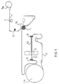
- a base film 2 is unwound from a supply roll 2a.
- the bottom film 2 is fed to a film feed 8, 9 via a deflection roller.
- the film feed consists of a first film feed roller block 8 and a second film feed roller block 9, which are arranged at a distance from one another.
- the film feed roller blocks 8, 9 are driven by a servo motor. In this way, the base film 2 can be moved in sections discontinuously.
- a heater 10 and a mold 4 are arranged between the first film feed roller block 8 and the second film feed roller block 9. The bottom film 2 is heated by the heater 10 to such an extent that it can easily be deformed in the molding tool 4.
- the molding tool 4 contains first recesses, not shown, through which containers 3, which are also referred to as courtyards, are formed in the base film 2.
- the first depressions of the molding tool 4 are arranged at a first distance a from one another in the direction of passage of the base film 2. This ensures that the containers 3 are also arranged at a distance a from one another in the longitudinal direction of the base film 2.
- the shaping of the container 3 into the bottom film 2 takes place when the bottom film 2 is stationary in the molding tool 4.
- the servo motor of the film feed roller blocks 8, 9 is driven so that the bottom film 2 moves forward by one section , which is slightly larger than the width of the molding tool 4 in the direction of passage of the bottom film 2.
- a take-off roller 5 is arranged behind the molding tool 4, which serves to apply a cover film 1 to the base film 2. Since the draw-off roller 5 is driven continuously, the base film 2 runs behind the mold 4 through a loop for buffering the different film length between the mold 4 and the draw-off roller 5 caused by the discontinuous operation of the mold 4.
- the base film 2 is deflected around the take-off roller 5 at approximately a right angle.
- the take-off roller 5 contains second recesses 6, into which the containers 3 are immersed during the deflection of the base film 2 around the take-off roller 5.
- the second depressions 6 of the draw-off roller 5 are somewhat larger than the first depressions of the molding tool 4. As a result, there is play between the containers 3 and the second depressions 6 of the draw-off roller 5.
- the second depressions 6 are formed in the take-off roller 5 such that they correspond to the arrangement of the first depressions of the molding tool 4 or the arrangement of the containers 3 formed in the base film 2. This means that the second depressions 6 are formed in sections in the take-off roller 5.
- the distance a 'of the second recesses 6 in the circumferential direction of the take-off roller 5 is slightly larger than the distance a of the containers 3.
- the distance b' of a respective last second recess 6 of a section to the respective first recess 6 of a subsequent section is slightly larger than that Distance b between the first and last container 3 of two successive sections, which is at the smallest advance of the bottom film 2 through the molding tool 4 sets. This ensures that the base film 2 is stretched around the take-off roller 5 during the deflection.
- a sealing roller 10 is arranged opposite the take-off roller 5 and rests movably with pressure on the take-off roller 5.
- the bottom film 2 is guided between the sealing roller 10 and the take-off roller 5.
- a cover film 1 is guided between the take-off roller 5 and the sealing roller 10.
- the cover film 1 is pre-printed and is removed from a second supply roll 1a.
- the sealing roller 10 is heated.
- the cover film 1 is pressed with pressure and heat onto the base film 2 by the sealing roll 10 and the take-off roll 5 such that the container 2 is sealed by the cover film 1.
- the base film 2 Due to the expansion of the base film 2 during the deflection around the take-off roller 5 and the action of the sealing roller 10 on the base film 2, the base film 2 is stretched permanently.
- the distance a ′′ of the containers 3 in the running direction of the base film 2 behind the take-off roller 5 and the distance b ′′ of the last container 3 of a section and the first container 3 of a subsequent section is thus greater than the corresponding distance a, b in the running direction of the base film 2 in front of the take-off roller 5.
- the permanent elongation of the base sheet 2 depends on the size of the advance of the base sheet 2 by the molding tool 4.
- the expansion of the base sheet 2 by the take-off roller 5 can be set.
- the cover film 1 contains print marks 11.
- the position of the print marks is detected by means of a print mark reading head 12. If the print mark 11 is in its target position, the print image matches the relevant containers 3. If the print mark 11 leaves its target position due to manufacturing tolerances that cannot be avoided, an offset occurs between the containers 3 and the print image in question.
- the print mark reading head 12 detects a deviation in the position of the print mark 11 in the running direction of the cover film 1, as is the case with the print mark designated 11 'in FIG. 2, the printed image rushes ahead of the associated containers 3.
- the base film 2 must therefore be shortened. This is done in that the feed of the bottom film 2 is somewhat reduced by the molding tool 4. Since the feed is generated by servomotors, it is very easy to change the feed. The position of the printed image can thus be corrected very easily.
- the print mark reading head 12 detects a deviation of the position of the print mark 11 against the running direction of the cover film 1, as is the case with the print mark designated 11 ′′ in FIG. 2, the print image runs behind the associated containers 3. To correct this, the base film 2 must therefore be extended. This is done by slightly increasing the advance of the base sheet 2 through the molding tool 4. The feed is increased or decreased by a corresponding control of the servomotors of the film feed roller assemblies 8, 9.
- a correction of the feed does not have any effect on these sections.
- a cover film brake 7 is provided, by means of which the transport of the cover film 1 can be stopped. Since the cover sheet 1 is printed by the sealing roller 10 on the take-off roller 5 and the take-off roller 5 rotates continuously, the cover sheet 1 is stretched, by means of which the position of the printed image with respect to the container 3 is already between the mold 4 and the take-off roller 5 sections.
Landscapes
- Engineering & Computer Science (AREA)
- Mechanical Engineering (AREA)
- Containers And Plastic Fillers For Packaging (AREA)
- Blow-Moulding Or Thermoforming Of Plastics Or The Like (AREA)
Applications Claiming Priority (2)
| Application Number | Priority Date | Filing Date | Title |
|---|---|---|---|
| DE19618769 | 1996-05-10 | ||
| DE19618769A DE19618769C1 (de) | 1996-05-10 | 1996-05-10 | Vorrichtung zum Aufbringen einer Deckfolie auf eine eingeformte Behälter aufweisende Bodenfolie |
Publications (1)
| Publication Number | Publication Date |
|---|---|
| EP0806360A1 true EP0806360A1 (fr) | 1997-11-12 |
Family
ID=7793891
Family Applications (1)
| Application Number | Title | Priority Date | Filing Date |
|---|---|---|---|
| EP97105988A Ceased EP0806360A1 (fr) | 1996-05-10 | 1997-04-11 | Dispositif pour appliquer une bande de recouvrement sur une bande support munie de récipieurs intégrés |
Country Status (3)
| Country | Link |
|---|---|
| US (1) | US5802821A (fr) |
| EP (1) | EP0806360A1 (fr) |
| DE (1) | DE19618769C1 (fr) |
Families Citing this family (10)
| Publication number | Priority date | Publication date | Assignee | Title |
|---|---|---|---|---|
| DE10038163A1 (de) * | 2000-08-04 | 2002-02-14 | Infineon Technologies Ag | Vorrichtung und Verfahren zur Bestückung von Transportgurten |
| DE10243084B3 (de) * | 2002-09-16 | 2004-01-29 | CSAT Gesellschaft für Computer-Systeme und Automations-Technik mbH | Vorrichtung zum positionsgenauen Zusammenfügen von zwei Materialsträngen |
| DE10356055A1 (de) * | 2003-12-01 | 2005-06-23 | Iwk Verpackungstechnik Gmbh | Blister-Verpackungsmaschine |
| US7987653B2 (en) * | 2004-03-03 | 2011-08-02 | Adaptsys Limited | Plastic embossed carrier tape process |
| US7392631B2 (en) * | 2004-05-07 | 2008-07-01 | I.M.A. Industria Macchine Automatichie S.P.A. | Blistering machine for producing blister packs |
| US20060042988A1 (en) * | 2004-08-31 | 2006-03-02 | Per Hjalmarsson | Folded blister package |
| DE102005018111A1 (de) * | 2005-04-19 | 2006-11-02 | Multivac Sepp Haggenmüller Gmbh & Co. Kg | Verfahren zum Abrollen von Bahnmaterial in einer Verpackungsmaschine und Verpackungsmaschine |
| FR2907424B1 (fr) * | 2006-10-19 | 2012-09-21 | Edixia | Procede et dispositif pour assurer un controle et un marquage d'emballages |
| ZA201505551B (en) * | 2014-10-23 | 2016-04-28 | H G Molenaar And Company Pty Limited | A feed control system for a lidding web |
| DE102019205172A1 (de) * | 2019-04-11 | 2020-10-15 | Syntegon Technology Gmbh | Verfahren und Vorrichtung zum Herstellen eines Verpackungskörpers einer Verpackung |
Citations (3)
| Publication number | Priority date | Publication date | Assignee | Title |
|---|---|---|---|---|
| DE3201315A1 (de) * | 1981-08-10 | 1983-07-07 | CKD AG, Komaki, Aichi | Verfahren zum ausrichten von markierungen beim formen und fuellen von verpackungen |
| DE3912054A1 (de) * | 1989-04-13 | 1990-10-18 | Iwk Verpackungstechnik Gmbh | Verfahren und vorrichtung zum herstellen von durch deckfolien abgedeckten behaeltern |
| EP0436476A1 (fr) * | 1989-12-29 | 1991-07-10 | Massimo Marchesini | Dispositif pour le thermoscellage d'un film sur une bande pour blisters, en particulier une bande en polypropylène |
Family Cites Families (5)
| Publication number | Priority date | Publication date | Assignee | Title |
|---|---|---|---|---|
| US3759011A (en) * | 1972-05-04 | 1973-09-18 | Reed Lane Inc | Packaging machine for packaging uniform articles such as pharmaceutical tablets |
| DE2254715C3 (de) * | 1972-11-09 | 1982-12-23 | Société d'Application Plastique, Mécanique et Electronique Plastimécanique S.A., Courbevoie | Verfahren zur Druckbildzentrierung bei Verpackungsmaschinen |
| US4349997A (en) * | 1980-04-21 | 1982-09-21 | Mitsubishi Jukogyo Kabushiki Kaisha | Device for enabling registry of operations in an apparatus for continuously forming containers filled with material |
| ES2017634B3 (es) * | 1985-12-24 | 1991-03-01 | Omnitech (Europe) Ltd | Maquina envasadora de introduccion horizontal |
| US5269123A (en) * | 1989-12-29 | 1993-12-14 | Massimo Marchesini | Device for sealing a film onto a blister band, particularly a polypropylene band |
-
1996
- 1996-05-10 DE DE19618769A patent/DE19618769C1/de not_active Expired - Fee Related
-
1997
- 1997-04-11 EP EP97105988A patent/EP0806360A1/fr not_active Ceased
- 1997-05-10 US US08/858,215 patent/US5802821A/en not_active Expired - Fee Related
Patent Citations (3)
| Publication number | Priority date | Publication date | Assignee | Title |
|---|---|---|---|---|
| DE3201315A1 (de) * | 1981-08-10 | 1983-07-07 | CKD AG, Komaki, Aichi | Verfahren zum ausrichten von markierungen beim formen und fuellen von verpackungen |
| DE3912054A1 (de) * | 1989-04-13 | 1990-10-18 | Iwk Verpackungstechnik Gmbh | Verfahren und vorrichtung zum herstellen von durch deckfolien abgedeckten behaeltern |
| EP0436476A1 (fr) * | 1989-12-29 | 1991-07-10 | Massimo Marchesini | Dispositif pour le thermoscellage d'un film sur une bande pour blisters, en particulier une bande en polypropylène |
Also Published As
| Publication number | Publication date |
|---|---|
| DE19618769C1 (de) | 1997-06-26 |
| US5802821A (en) | 1998-09-08 |
Similar Documents
| Publication | Publication Date | Title |
|---|---|---|
| DE19824797B4 (de) | Beutelherstellungsvorrichtung und Verfahren zum Herstellen von Folienbeutel | |
| DE3789886T2 (de) | Regulierung von Seitenabweichungen eines Bandes. | |
| EP2740672B2 (fr) | Machine d'emballage par emboutissage avec positionnement cyclique précis d'un poste de scellage et méthode correspondante | |
| DE3045951C2 (de) | Einrichtung zum Führen einer Materialbahn | |
| DE102007049670B4 (de) | Verfahren zur Registerkorrektur bei einer Bearbeitungsmaschine sowie Bearbeitungsmaschine | |
| EP0475095A1 (fr) | Dispositif d'alignement d'une bande continue par rapport à une deuxième bande | |
| EP3202673B1 (fr) | Machine d'emballage par emboutissage | |
| EP2860119A1 (fr) | Machine d'emballage par emboutissage et procédé | |
| EP1457324A1 (fr) | Procédé et dispositif pour imprimer une bande | |
| DE69724161T2 (de) | Vorrichtung zum Herstellen von Informationen tragenden Gelatinkapseln | |
| WO2010043345A1 (fr) | Moyen de transport et machine d'emballage s'adaptant à la largeur de film | |
| DE2635727A1 (de) | Vorrichtung zur einhaltung der passgenauigkeit der farben beim druck auf duenne materialien, anwendbar auf eine rotationsdruckmaschine fuer mehrere farben | |
| CH677338A5 (fr) | ||
| DE19618769C1 (de) | Vorrichtung zum Aufbringen einer Deckfolie auf eine eingeformte Behälter aufweisende Bodenfolie | |
| EP1924435B1 (fr) | Presse et procede pour corriger le reperage | |
| DE10243084B3 (de) | Vorrichtung zum positionsgenauen Zusammenfügen von zwei Materialsträngen | |
| DE19516368A1 (de) | Verfahren und Vorrichtung zur Anpassung der Lage von Druckplatten an die Verformung des zu bedruckenden Papieres | |
| DE2254715B2 (de) | Verfahren zur Druckbildzentrierung bei Verpackungsmaschinen | |
| DE2744280C3 (de) | Vorschubeinrichtung für schrittweise zu transportierendes Folienbandmaterial | |
| EP3081516B1 (fr) | Procédé et dispositif de fabrication d'un élément de sécurité | |
| DE69007747T2 (de) | Vertikale tänzerrolle mit gleichbleibendem torsionsmoment. | |
| DE1300850B (de) | Vorrichtung zum Auftragen und Praegen eines Kunststoffmaterials auf relativ duenne, bedruckte Traeger | |
| EP1155831B1 (fr) | Procédé et dispositif d'estampage à chaud. | |
| DE19836211A1 (de) | Rotationsschneideverfahren für Folienbahnen und dergleichen sowie Vorrichtung zur Durchführung des Verfahrens | |
| EP3077306B1 (fr) | Dispositif et procédé de découpage d'un matériau en bande en bandes partielles et d'écartement des bandes partielles |
Legal Events
| Date | Code | Title | Description |
|---|---|---|---|
| PUAI | Public reference made under article 153(3) epc to a published international application that has entered the european phase |
Free format text: ORIGINAL CODE: 0009012 |
|
| AK | Designated contracting states |
Kind code of ref document: A1 Designated state(s): AT BE CH DE DK ES FI FR GB GR IE IT LI NL PT SE |
|
| 17P | Request for examination filed |
Effective date: 19971016 |
|
| GRAG | Despatch of communication of intention to grant |
Free format text: ORIGINAL CODE: EPIDOS AGRA |
|
| 17Q | First examination report despatched |
Effective date: 20000530 |
|
| STAA | Information on the status of an ep patent application or granted ep patent |
Free format text: STATUS: THE APPLICATION HAS BEEN REFUSED |
|
| 18R | Application refused |
Effective date: 20001115 |