EP2740672B2 - Machine d'emballage par emboutissage avec positionnement cyclique précis d'un poste de scellage et méthode correspondante - Google Patents
Machine d'emballage par emboutissage avec positionnement cyclique précis d'un poste de scellage et méthode correspondante Download PDFInfo
- Publication number
- EP2740672B2 EP2740672B2 EP13002228.8A EP13002228A EP2740672B2 EP 2740672 B2 EP2740672 B2 EP 2740672B2 EP 13002228 A EP13002228 A EP 13002228A EP 2740672 B2 EP2740672 B2 EP 2740672B2
- Authority
- EP
- European Patent Office
- Prior art keywords
- station
- sealing station
- reference element
- packaging machine
- forming
- Prior art date
- Legal status (The legal status is an assumption and is not a legal conclusion. Google has not performed a legal analysis and makes no representation as to the accuracy of the status listed.)
- Active
Links
Images

Classifications
-
- B—PERFORMING OPERATIONS; TRANSPORTING
- B65—CONVEYING; PACKING; STORING; HANDLING THIN OR FILAMENTARY MATERIAL
- B65B—MACHINES, APPARATUS OR DEVICES FOR, OR METHODS OF, PACKAGING ARTICLES OR MATERIALS; UNPACKING
- B65B47/00—Apparatus or devices for forming pockets or receptacles in or from sheets, blanks, or webs, comprising essentially a die into which the material is pressed or a folding die through which the material is moved
- B65B47/02—Apparatus or devices for forming pockets or receptacles in or from sheets, blanks, or webs, comprising essentially a die into which the material is pressed or a folding die through which the material is moved with means for heating the material prior to forming
-
- B—PERFORMING OPERATIONS; TRANSPORTING
- B65—CONVEYING; PACKING; STORING; HANDLING THIN OR FILAMENTARY MATERIAL
- B65B—MACHINES, APPARATUS OR DEVICES FOR, OR METHODS OF, PACKAGING ARTICLES OR MATERIALS; UNPACKING
- B65B57/00—Automatic control, checking, warning, or safety devices
- B65B57/02—Automatic control, checking, warning, or safety devices responsive to absence, presence, abnormal feed, or misplacement of binding or wrapping material, containers, or packages
- B65B57/04—Automatic control, checking, warning, or safety devices responsive to absence, presence, abnormal feed, or misplacement of binding or wrapping material, containers, or packages and operating to control, or to stop, the feed of such material, containers, or packages
-
- B—PERFORMING OPERATIONS; TRANSPORTING
- B65—CONVEYING; PACKING; STORING; HANDLING THIN OR FILAMENTARY MATERIAL
- B65B—MACHINES, APPARATUS OR DEVICES FOR, OR METHODS OF, PACKAGING ARTICLES OR MATERIALS; UNPACKING
- B65B61/00—Auxiliary devices, not otherwise provided for, for operating on sheets, blanks, webs, binding material, containers or packages
- B65B61/02—Auxiliary devices, not otherwise provided for, for operating on sheets, blanks, webs, binding material, containers or packages for perforating, scoring, slitting, or applying code or date marks on material prior to packaging
- B65B61/025—Auxiliary devices, not otherwise provided for, for operating on sheets, blanks, webs, binding material, containers or packages for perforating, scoring, slitting, or applying code or date marks on material prior to packaging for applying, e.g. printing, code or date marks on material prior to packaging
-
- B—PERFORMING OPERATIONS; TRANSPORTING
- B65—CONVEYING; PACKING; STORING; HANDLING THIN OR FILAMENTARY MATERIAL
- B65B—MACHINES, APPARATUS OR DEVICES FOR, OR METHODS OF, PACKAGING ARTICLES OR MATERIALS; UNPACKING
- B65B9/00—Enclosing successive articles, or quantities of material, e.g. liquids or semiliquids, in flat, folded, or tubular webs of flexible sheet material; Subdividing filled flexible tubes to form packages
- B65B9/02—Enclosing successive articles, or quantities of material between opposed webs
- B65B9/04—Enclosing successive articles, or quantities of material between opposed webs one or both webs being formed with pockets for the reception of the articles, or of the quantities of material
-
- B—PERFORMING OPERATIONS; TRANSPORTING
- B29—WORKING OF PLASTICS; WORKING OF SUBSTANCES IN A PLASTIC STATE IN GENERAL
- B29C—SHAPING OR JOINING OF PLASTICS; SHAPING OF MATERIAL IN A PLASTIC STATE, NOT OTHERWISE PROVIDED FOR; AFTER-TREATMENT OF THE SHAPED PRODUCTS, e.g. REPAIRING
- B29C65/00—Joining or sealing of preformed parts, e.g. welding of plastics materials; Apparatus therefor
- B29C65/78—Means for handling the parts to be joined, e.g. for making containers or hollow articles, e.g. means for handling sheets, plates, web-like materials, tubular articles, hollow articles or elements to be joined therewith; Means for discharging the joined articles from the joining apparatus
- B29C65/7802—Positioning the parts to be joined, e.g. aligning, indexing or centring
-
- B—PERFORMING OPERATIONS; TRANSPORTING
- B29—WORKING OF PLASTICS; WORKING OF SUBSTANCES IN A PLASTIC STATE IN GENERAL
- B29C—SHAPING OR JOINING OF PLASTICS; SHAPING OF MATERIAL IN A PLASTIC STATE, NOT OTHERWISE PROVIDED FOR; AFTER-TREATMENT OF THE SHAPED PRODUCTS, e.g. REPAIRING
- B29C65/00—Joining or sealing of preformed parts, e.g. welding of plastics materials; Apparatus therefor
- B29C65/78—Means for handling the parts to be joined, e.g. for making containers or hollow articles, e.g. means for handling sheets, plates, web-like materials, tubular articles, hollow articles or elements to be joined therewith; Means for discharging the joined articles from the joining apparatus
- B29C65/7858—Means for handling the parts to be joined, e.g. for making containers or hollow articles, e.g. means for handling sheets, plates, web-like materials, tubular articles, hollow articles or elements to be joined therewith; Means for discharging the joined articles from the joining apparatus characterised by the feeding movement of the parts to be joined
- B29C65/7888—Means for handling of moving sheets or webs
- B29C65/7891—Means for handling of moving sheets or webs of discontinuously moving sheets or webs
-
- B—PERFORMING OPERATIONS; TRANSPORTING
- B29—WORKING OF PLASTICS; WORKING OF SUBSTANCES IN A PLASTIC STATE IN GENERAL
- B29C—SHAPING OR JOINING OF PLASTICS; SHAPING OF MATERIAL IN A PLASTIC STATE, NOT OTHERWISE PROVIDED FOR; AFTER-TREATMENT OF THE SHAPED PRODUCTS, e.g. REPAIRING
- B29C66/00—General aspects of processes or apparatus for joining preformed parts
- B29C66/01—General aspects dealing with the joint area or with the area to be joined
- B29C66/05—Particular design of joint configurations
- B29C66/10—Particular design of joint configurations particular design of the joint cross-sections
- B29C66/11—Joint cross-sections comprising a single joint-segment, i.e. one of the parts to be joined comprising a single joint-segment in the joint cross-section
- B29C66/112—Single lapped joints
-
- B—PERFORMING OPERATIONS; TRANSPORTING
- B29—WORKING OF PLASTICS; WORKING OF SUBSTANCES IN A PLASTIC STATE IN GENERAL
- B29C—SHAPING OR JOINING OF PLASTICS; SHAPING OF MATERIAL IN A PLASTIC STATE, NOT OTHERWISE PROVIDED FOR; AFTER-TREATMENT OF THE SHAPED PRODUCTS, e.g. REPAIRING
- B29C66/00—General aspects of processes or apparatus for joining preformed parts
- B29C66/01—General aspects dealing with the joint area or with the area to be joined
- B29C66/05—Particular design of joint configurations
- B29C66/10—Particular design of joint configurations particular design of the joint cross-sections
- B29C66/13—Single flanged joints; Fin-type joints; Single hem joints; Edge joints; Interpenetrating fingered joints; Other specific particular designs of joint cross-sections not provided for in groups B29C66/11 - B29C66/12
- B29C66/131—Single flanged joints, i.e. one of the parts to be joined being rigid and flanged in the joint area
-
- B—PERFORMING OPERATIONS; TRANSPORTING
- B29—WORKING OF PLASTICS; WORKING OF SUBSTANCES IN A PLASTIC STATE IN GENERAL
- B29C—SHAPING OR JOINING OF PLASTICS; SHAPING OF MATERIAL IN A PLASTIC STATE, NOT OTHERWISE PROVIDED FOR; AFTER-TREATMENT OF THE SHAPED PRODUCTS, e.g. REPAIRING
- B29C66/00—General aspects of processes or apparatus for joining preformed parts
- B29C66/50—General aspects of joining tubular articles; General aspects of joining long products, i.e. bars or profiled elements; General aspects of joining single elements to tubular articles, hollow articles or bars; General aspects of joining several hollow-preforms to form hollow or tubular articles
- B29C66/51—Joining tubular articles, profiled elements or bars; Joining single elements to tubular articles, hollow articles or bars; Joining several hollow-preforms to form hollow or tubular articles
- B29C66/53—Joining single elements to tubular articles, hollow articles or bars
- B29C66/534—Joining single elements to open ends of tubular or hollow articles or to the ends of bars
- B29C66/5346—Joining single elements to open ends of tubular or hollow articles or to the ends of bars said single elements being substantially flat
- B29C66/53461—Joining single elements to open ends of tubular or hollow articles or to the ends of bars said single elements being substantially flat joining substantially flat covers and/or substantially flat bottoms to open ends of container bodies
-
- B—PERFORMING OPERATIONS; TRANSPORTING
- B29—WORKING OF PLASTICS; WORKING OF SUBSTANCES IN A PLASTIC STATE IN GENERAL
- B29C—SHAPING OR JOINING OF PLASTICS; SHAPING OF MATERIAL IN A PLASTIC STATE, NOT OTHERWISE PROVIDED FOR; AFTER-TREATMENT OF THE SHAPED PRODUCTS, e.g. REPAIRING
- B29C66/00—General aspects of processes or apparatus for joining preformed parts
- B29C66/80—General aspects of machine operations or constructions and parts thereof
- B29C66/84—Specific machine types or machines suitable for specific applications
- B29C66/849—Packaging machines
-
- B—PERFORMING OPERATIONS; TRANSPORTING
- B29—WORKING OF PLASTICS; WORKING OF SUBSTANCES IN A PLASTIC STATE IN GENERAL
- B29L—INDEXING SCHEME ASSOCIATED WITH SUBCLASS B29C, RELATING TO PARTICULAR ARTICLES
- B29L2031/00—Other particular articles
- B29L2031/712—Containers; Packaging elements or accessories, Packages
-
- B—PERFORMING OPERATIONS; TRANSPORTING
- B65—CONVEYING; PACKING; STORING; HANDLING THIN OR FILAMENTARY MATERIAL
- B65B—MACHINES, APPARATUS OR DEVICES FOR, OR METHODS OF, PACKAGING ARTICLES OR MATERIALS; UNPACKING
- B65B47/00—Apparatus or devices for forming pockets or receptacles in or from sheets, blanks, or webs, comprising essentially a die into which the material is pressed or a folding die through which the material is moved
-
- B—PERFORMING OPERATIONS; TRANSPORTING
- B65—CONVEYING; PACKING; STORING; HANDLING THIN OR FILAMENTARY MATERIAL
- B65B—MACHINES, APPARATUS OR DEVICES FOR, OR METHODS OF, PACKAGING ARTICLES OR MATERIALS; UNPACKING
- B65B61/00—Auxiliary devices, not otherwise provided for, for operating on sheets, blanks, webs, binding material, containers or packages
- B65B61/04—Auxiliary devices, not otherwise provided for, for operating on sheets, blanks, webs, binding material, containers or packages for severing webs, or for separating joined packages
- B65B61/06—Auxiliary devices, not otherwise provided for, for operating on sheets, blanks, webs, binding material, containers or packages for severing webs, or for separating joined packages by cutting
Definitions
- the invention relates to a deep-drawing packaging machine according to the features of claim 1 and to a method for operating the deep-drawing packaging machine according to the features of claim 9.
- Thermoforming packaging machines with workstations adjustable in the direction of production for example a forming, sealing and cutting station, are known which can be adjusted depending on the position of a print mark on a lower film, the print mark being detected by a print mark sensor in front of the forming station.
- the work stations have motorized adjustment drives with position measuring devices. Changeable distances between successive print marks are determined by the control using the print mark sensor and the position of the forming, sealing and cutting station is regulated accordingly in order to adapt the distances between the work stations. This is to ensure that the forming station forms troughs to match the position of the print mark, the sealing station creates sealing seams according to the position of the troughs, and the cutting station cuts the sealed packs to match the sealing seams and separates the packs.
- An adjustment of the sealing station after detection of a print mark has an effect only many advances or advantages of the detected print mark later, since an insertion path is provided between the forming station and the sealing station for inserting products to be packaged into the shaped troughs. Negative influences due to irregular film shrinkage or tolerances in the feed movements of the feed chains are not taken into account.
- the result is a generous dimensioning of the width of the packing webs and edges in the feed direction, so that the sealing seam can be produced on the edges with a sufficient width and after the subsequent cutting process the sealing seam still has a width in order to achieve the desired sealing quality.
- This generous design leads to increased film consumption due to a large amount of film waste.
- a print mark sensor is used for the top film.
- This print mark sensor is located just as far in front of the sealing station as the forming station is located in front of the Siegelsta sealing station, so that the print mark sensor always detects the print mark that corresponds to the section of film that belongs to the lower mold just formed in the same machine cycle.
- the GB 1 296 251 discloses a device in which the deformation of a bottom film is to be adapted to a previously applied print.
- photocells are provided that recognize the markings made on the foil in order to be able to subsequently adapt the position of the forming station and a sealing station, among other things.
- the not pre-published DE 10 2011 108 939 also describes a packaging machine in which the position of sealing seams is detected in order to subsequently be able to align a cutting device to match the position of the sealing seams.
- the object of the present invention is to improve a thermoforming packaging machine with regard to the film consumption.
- the thermoforming packaging machine operates in operation with a certain feed length per work cycle. It comprises a molding station for molding troughs into a bottom film, a sealing station, preferably a cutting station and a control system, the sealing station having an adjusting device along a production direction and a displacement measuring device.
- a measuring system for determining the position of the reference element is provided and the control unit is configured to position the sealing station in accordance with the determined position of the reference element relative to the troughs by means of the adjusting device.
- the position of the troughs which are already in the sealing station is determined when the feed movement of the lower film or the troughs has been completed. Determining the position of the reference element when the bottom film is stationary has the advantage that inaccuracies in the positioning of the bottom film or the troughs in the sealing station at the end of the feed movement are taken into account and inaccuracies in dynamic detection of the reference element can be eliminated even during the feed movement.
- the position control in the end position during the feed movement of the lower film by means of a servo drive can be simplified, as can the detection of the reference element.
- the measuring system is preferably provided for contactless determination of the position of the reference element.
- a device is arranged in front of (i.e. upstream) the molding station in order to introduce a reference element into the lower film, the position of the troughs being detectable by means of a detection of the reference element via the measuring system.
- the device is preferably coupled to the molding station.
- the molding station and the device can be driven by means of a common drive
- the reference element has a fixed and constant distance from the troughs formed in the same work cycle. There is thus a fixed relationship between the position of the troughs of a common cycle and the associated reference element. This enables the use of inexpensive measuring systems, since only the reference element has to be detected, since the troughs have a predetermined position with respect to the reference element.
- the reference element can be, for example, a punched-out in the form of a hole or an embossing of a knob. It is also conceivable to have several narrow punched-out areas, e.g. B. are attached on both sides of the troughs near a clamp chain provided on both sides for film transport. For this purpose, two measuring systems are provided in front of or at the sealing station in order to detect such reference elements from both sides.
- the measuring system preferably has a camera or a reflex sensor, for example a light barrier.
- the reflex sensor is particularly suitable for detecting a reference element in the form of a punched-out area.
- the camera is particularly suitable for detecting the position of the reference element at a standstill after the lower film and thus the troughs have been moved.
- the path measuring device of the sealing station is a magnetostrictive linear encoder in order to provide a hygienic design.
- a linear encoder works in a contactless manner with a measuring sensor in such a way that even the gap between the linear sensor and the measuring sensor is easy to clean and resistant to conventional cleaning agents.
- An adjustment path of the sealing station of up to 1000 mm, preferably greater than 300 mm, is preferably provided in order not only to compensate for fluctuations in and against the production direction, but also to be able to move the sealing station, for example, into a tool change position in which a sealing tool bottom and / or top part laterally or can be removed from the thermoforming packaging machine for maintenance, cleaning or replacement purposes.
- a further measuring system is provided for the contactless determination of the position of the troughs, which are fed to the cutting station in a next working cycle, and the control unit is configured to position the cutting station according to the determined position of the troughs precisely in its position relative to the troughs to regulate another adjustment device.
- the control unit is configured to position the cutting station according to the determined position of the troughs precisely in its position relative to the troughs to regulate another adjustment device.
- a trend control for the molding station is provided by means of the control.
- the term tendency control means that the control station recognizes a repetitive positioning of the sealing station in only one direction, and to counteract this, the control adjusts the molding station in the opposite direction so that further positioning of the sealing station in one direction can be avoided.
- the forming station and / or the sealing station can be moved into a tool change position in or against the production direction in order to move it to a position that is laterally accessible with respect to the thermoforming packaging machine, in order to be able to carry out a tool change ergonomically and without influencing a film.
- thermoforming packaging machine which comprises a molding station for molding troughs in a bottom film, a sealing station and a controller, provides that a device introduces a reference element into the bottom film and by means of a measuring system the position of the reference element and thus at least indirectly the position of the troughs is also determined and the control uses an adjusting device to position the sealing station in a predetermined or predeterminable position relative to the troughs.
- the position of the troughs that are already in the sealing station and have completed the feed movement is determined.
- the sealing station can always be positioned exactly in relation to the position of the troughs to be sealed and tolerances can be ignored, which leads to a reduction in film consumption.
- the measuring system detects a reference element that was introduced into the lower film by means of a device that is arranged in front of the forming station in order to determine the position of the troughs in the control.
- the controller determines from a changing The position of the troughs prefers a tendency and adjusts the position of the forming station with respect to a production direction by means of a further adjusting device.
- a parameter for the length of the intermittent feeds can also be adjusted in the control.
- control detects the position of the sealing station by means of a displacement measuring device of the adjusting device which is aligned longitudinally to the production direction.
- a mechanical scanning device is conceivable in order to scan a punched-out or a knob as a reference element.
- a camera preferably detects the position of the reference element at a standstill after a feed movement of the lower film by means of a film transport chain. With such detection of the reference element in the subsequent standstill, the feed movement of the film transport chain can be omitted and the accuracy of the positioning of the sealing station can be further increased. Inaccuracies or different positions of the film transport chain, which occur due to different friction conditions along the guides of the film transport chain, are fully taken into account, since the detection of the position of the reference element and thus also the position of the troughs only after the positioning of the film transport chains when the troughs to be sealed are at a standstill is carried out.
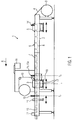
- Fig. 1 shows a cyclic thermoforming packaging machine 1 with a machine frame 2, which is aligned along a production direction R.
- a roll-off device 3 is provided for a lower film 4.
- the lower film 4 is fed to a forming station 5 by means of two feed chains (not shown) with a feed length V per work cycle in the production direction R.
- an insertion section 6 for inserting a product 7 into shaped troughs 8 downstream of the molding station 5 is shown.
- a sealing station 9 for closing the troughs 8 filled with product 7 with a cover film 10 and a first cutting station 11 which is designed as a cross-cut.
- a second cutting device 12, which is arranged downstream of the first cutting device 11, is designed as a longitudinal cut and separates the packages 13.
- a plurality of troughs 8 shaped in the production direction R can be arranged in the lower film, which are transported intermittently downstream in one cycle as a format with, for example, three troughs 8 arranged next to one another.
- the forming station 5 forms several rows of troughs 8 and that this format of troughs 8, which are formed into the bottom film 4 in one working cycle in the forming station 5, is transported in cycles in the production direction R.
- thermoforming packaging machine 1 The mode of operation of the thermoforming packaging machine 1 shown will be explained in more detail below.
- the bottom film 4 unrolled by the unrolling device 3 is gripped by the feed chains on both sides and fed to the forming station 5.
- one or more troughs 8 are formed in the bottom film 4 and, in a defined position relative to the troughs 8, a reference element 40 (see Fig. 3 ) by means of a punching device 14 in the lower film 4 in an area which lies outside the troughs 8 and outside or between sealing seams 41 produced later.
- the reference element 40 can be a hole with a diameter of 5 mm.
- the bottom film 4 with the shaped troughs 8 is transported intermittently along the insertion section 6.
- the troughs 8 are filled with products 7 manually or automatically, for example by means of pickers.
- a measuring system 15 is mounted above the lower film 4 in order to detect the reference element 40 during the cyclical advancing movement of the lower film 4 or to determine the position of the reference element 40 at a standstill, for example by means of a camera 15a.
- the information about the position of the reference element 40 in the cycle Tx is transmitted to a controller 16.
- the position of the trough 8 is Reference element 40 is stored, so that the control 16 adjusts the sealing station 9 for the cycle Ty by means of an adjusting device 17 such that the troughs 8 which were recorded in the cycle Tx correspond exactly with their position in the following cycle Ty in the sealing station 9 ,
- the adjusting device 17 is actuated after the sealing process for sealing the cover film 10 onto the lower film 4 has been completed and a lower sealing tool part 18 has moved downward out of the collision area of the troughs 8 in order to permit the next advancing movement of the lower film 8.
- the adjustment of the sealing station 9 always relates to the position of the troughs previously recorded in the cycle, since the detection of the troughs 8 in cycle Tx results in an adjustment of the sealing station 9 in the immediately following cycle Ty.
- control 16 can also perform an adjustment of the first cutting station 11 in order to partially separate the packaging 13 or the bottom film 4 and the cover film 10 directly at the sealing seam 41, oriented transversely to the production direction R.
- the troughs 8 can be recorded in the Tx cycle by means of the measuring system 15 in front of the sealing station 9, or another measuring system 19 in the Tz cycle in front of the cutting station 11 determines the position of the troughs 8 or the sealing seams 41 produced in the sealing station 9 (see Figure 3 ).
- the second cutting device 12, which is arranged at the end of the deep-drawing packaging machine 1, is designed as a longitudinal cut and separates the packaging 13 along the production direction R, so that the packaging 13 can be supplied to the further production process in individual cases.
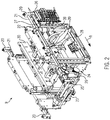
- the sealing station 9 is shown without an upper sealing tool part and the lower sealing tool part 18.
- the sealing station 9 is attached to the machine frame 2 via six fastening elements 20.
- a lifting device 22 can be moved in and against the production direction R along guide rails 21. Via a servo drive 23 and a belt transmission 24, the lifting device 22 can be adjusted along the production direction R relative to the machine frame 2 by means of a toothed belt 25.
- the position of the sealing station 9 or the lifting device 22 relative to the machine frame 2 can be determined via a displacement measuring device 26, the displacement measuring device 26 being a magnetostrictive non-contact linear encoder which is aligned along the machine frame 2.
- An associated sensor 27 is attached to the lifting device 22.
- the lifting device 22 has a toggle lever mechanism 28 with a servo drive 29 in order to (not in Fig. 2 illustrated) lower part of the sealing tool 18, which is provided on the receptacles 30, to be raised and lowered vertically.
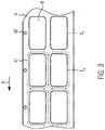
- Fig. 3 shows in a plan view of the lower film 4 two troughs 8, which are arranged in two lanes, and a single-row cycle or feed.
- the reference element 40 is located on the right-hand edge of the lower film 4, as seen in the production direction R, next to or outside the sealing seam 41.
- the cycle Tx in front of the sealing station 9 changes with a feed into the next cycle Ty in the sealing station.
- a trend control for the forming station 5 is explained in more detail. If the control 16 determines that the sealing station 9 has been adjusted several times in succession in the same direction, then the molding station 5 can be adjusted in the opposite direction by means of its own adjustment device in order to minimize a continuous adjustment of the sealing station 9 in only one direction or quit.
- the adjustment of the sealing station 9 serves primarily to compensate for irregularities in the advance of the lower film 4 or irregularities in the lower film 4 itself, by referring to the position of the trough 8 with precise timing.
- Fig. 4 shows a variant of the in Fig. 1 Thermoforming packaging machine shown 1.
- a device 14a for generating a reference element 40x, 40y is according to the invention and deviates from the illustration in Fig. 4 arranged in front of the molding station 5 and mechanically connected to the molding station 5.
- troughs 8 of a cycle Tx are simultaneously deep-drawn in the forming station 5, while the device 14a forms a reference element 40x on the right edge of the lower film 4.
- the two troughs 8 of the cycle Tx arranged next to one another are at a defined distance from the assigned reference element 40x.
- This distance can be entered into the controller 16 and is calculated when the reference element 40x is detected in front of the sealing station 9 by means of a camera 15a in the controller 16 in order to position the sealing station 9 in accordance with the troughs 8 of the cycle Tx located therein.
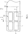
- Fig. 5 shows a plan view of the molding station.
- the molding station 5 two troughs 8 of the cycle Tx are produced and the device 14a forms a reference element 40x in the form of a knob with a diameter of, for example, 3 mm into the lower film 4.
- troughs 8 of a cycle Ty and a reference element were formed 40y generated.
- the reference element 40x, 40y Since the respective reference element 40x, 40y has a distance A upstream of the troughs 8 in the production direction R, the reference element 40x, 40y can be detected outside or in front of the sealing station 9 after the associated troughs 8 are in the sealing station. The feed movement is completed and the troughs 8 and the reference element 40x, 40y stand still.
- the camera 15a has a defined distance from the sealing station 9 and this distance can be entered into the controller 16 and is calculated accordingly.
- a reference image of the reference element 40x, 40y is stored or taught in the camera 15a.
- a deviation of the current position of the reference element 40x, 40y from the reference image is shown together with the distance of the camera 15a to the sealing station 9 and the distance A of the reference element 40x to the troughs 8 in the controller 16 and the sealing station 9 is positioned such that the sealing seam 41 subsequently produced is in an exact position to the troughs 8.
- the distance A can be, for example, the distance from the center of a circular knob deformation of the reference element 40x to the central axis of the troughs 8 of the cycle Tx.
- the distance A between the reference element 40x and troughs 8 of the cycle Tx are conceivable.
- the reference element 40x can have various shapes, preferably central shapes such as a circle or a circular knob, which is shaped upwards or downwards in the bottom film 4. Punching is also conceivable, preferably circular hole punching.
Landscapes
- Engineering & Computer Science (AREA)
- Mechanical Engineering (AREA)
- Containers And Plastic Fillers For Packaging (AREA)
- Closing Of Containers (AREA)
Claims (9)
- Machine d'emballage par emboutissage ou thermoformage (1), comprenant un poste de formage (5) destiné à former des cavités (8) dans une feuille inférieure (4), un poste de scellage (9) et une commande (16), le poste de scellage (9) comportant un dispositif de déplacement (17) pour assurer un déplacement de sa position le long d'une direction de production (R), et un dispositif de mesure de déplacement (26), et la machine d'emballage par emboutissage ou thermoformage (1) étant conçue pour un fonctionnement cyclique avec une longueur d'avancement (V) par cycle de travail, machine d'emballage dans laquelle il est prévu un dispositif (14a) pour insérer un élément de référence (40x, 40y) dans la feuille inférieure (4), caractérisée en ce que dans le poste de scellage (9) ou à l'intérieur d'une longueur d'avancement (V), en amont du poste de scellage (9), il est prévu un système de mesure (15a) pour déterminer la position de l'élément de référence (40x, 40y), la commande (16) étant configurée pour régler la position du poste de scellage (9) par rapport aux cavités (8), au moyen du dispositif de déplacement (17), conformément à la position de l'élément de référence (40x, 40y) ayant été déterminée, le dispositif (14a) étant agencé avant le poste de formage (5) et configuré pour insérer un élément de référence (40x, 40y) dans la feuille inférieure (4), dans une position définie par rapport aux cavités (8), et la détection de l'élément de référence (40x, 40y) par l'intermédiaire du système de mesure (15a) permettant de relever la position des cavités (8).
- Machine d'emballage par emboutissage ou thermoformage selon la revendication 1, caractérisée en ce que le système de mesure (15a) est prévu pour la détermination sans contact de la position de l'élément de référence (40x, 40y).
- Machine d'emballage par emboutissage ou thermoformage selon l'une des revendications précédentes, caractérisée en ce que le système de mesure (15a) comporte une caméra.
- Machine d'emballage par emboutissage ou thermoformage selon l'une des revendications précédentes, caractérisée en ce que le dispositif de mesure de déplacement (26) est un capteur linéaire magnétostrictif.
- Machine d'emballage par emboutissage ou thermoformage selon l'une des revendications précédentes, caractérisée en ce qu'il est prévu un déplacement du poste de scellage (9) jusqu'à 1000 mm.
- Machine d'emballage par emboutissage ou thermoformage selon l'une des revendications précédentes, caractérisée en ce qu'il est prévu un autre système de mesure (19) pour la détermination sans contact de la position des cavités (8), qui sont transmises dans un cycle de travail suivant (Tz) au poste de découpage (11), et en ce que la commande (16) est configurée pour régler la position du poste de découpage (11) conformément à la position des cavités (8) ayant été déterminée, de manière précise pour le cycle considéré, dans sa position par rapport aux cavités (8), au moyen d'un autre dispositif de déplacement.
- Machine d'emballage par emboutissage ou thermoformage selon l'une des revendications précédentes, caractérisée en ce que le poste de formage (5) et/ou le poste de scellage (9) peut être déplacé dans une position de changement d'outillage.
- Machine d'emballage par emboutissage ou thermoformage selon l'une des revendications précédentes, caractérisée en ce que la commande (16) est configurée pour la saisie et la mémorisation de positions de consigne du poste de formage (5) et/ou du poste de scellage (9), dans des formules, dans la commande (16).
- Procédé pour faire fonctionner une machine d'emballage par emboutissage ou thermoformage (1), qui comprend un poste de formage (5) pour assurer le formage de cavités (8) dans une feuille inférieure (4), un poste de scellage (9) et une commande (16), procédé d'après lequel un dispositif (14a) agencé avant le poste de formage (5), insère dans la feuille inférieure (4), un élément de référence (40x, 40y), qui présente une distance (A) définie et restant identique par rapport aux cavités (8) des cycles correspondants (Tx, Ty), d'après lequel à l'aide d'un système de mesure (15a), on détermine la position de l'élément de référence (40x, 40y) des cavités (8) qui se trouvent déjà dans le poste de scellage (9) et ont déjà achevé leur mouvement d'avance,
d'après lequel le système de mesure (15a), grâce à la détection de l'élément de référence (40x, 40y), fournit une information sur la base de laquelle la commande (16) détermine la position des cavités (8),
d'après lequel la commande (16), à l'aide d'un dispositif de déplacement (17), positionne le poste de scellage (9) dans une position prédéterminée par rapport à l'élément de référence (40x, 40y),
et d'après lequel la commande (16) relève la position du poste de scellage (9) à l'aide d'un dispositif de mesure de déplacement (26) du dispositif de déplacement (17), qui est orienté le long de la direction de production (R).
Priority Applications (2)
| Application Number | Priority Date | Filing Date | Title |
|---|---|---|---|
| EP13002228.8A EP2740672B2 (fr) | 2012-12-04 | 2013-04-26 | Machine d'emballage par emboutissage avec positionnement cyclique précis d'un poste de scellage et méthode correspondante |
| US14/095,852 US20140150377A1 (en) | 2012-12-04 | 2013-12-03 | Thermo-forming packaging machine with true-to-cycle positioning of a sealing station |
Applications Claiming Priority (2)
| Application Number | Priority Date | Filing Date | Title |
|---|---|---|---|
| EP12008109.6A EP2740679B2 (fr) | 2012-12-04 | 2012-12-04 | Machine d'emballage par emboutissage avec positionnement cyclique précis d'un poste de scellage et méthod correspondante |
| EP13002228.8A EP2740672B2 (fr) | 2012-12-04 | 2013-04-26 | Machine d'emballage par emboutissage avec positionnement cyclique précis d'un poste de scellage et méthode correspondante |
Publications (3)
| Publication Number | Publication Date |
|---|---|
| EP2740672A1 EP2740672A1 (fr) | 2014-06-11 |
| EP2740672B1 EP2740672B1 (fr) | 2016-12-07 |
| EP2740672B2 true EP2740672B2 (fr) | 2020-01-22 |
Family
ID=47429510
Family Applications (2)
| Application Number | Title | Priority Date | Filing Date |
|---|---|---|---|
| EP12008109.6A Active EP2740679B2 (fr) | 2012-12-04 | 2012-12-04 | Machine d'emballage par emboutissage avec positionnement cyclique précis d'un poste de scellage et méthod correspondante |
| EP13002228.8A Active EP2740672B2 (fr) | 2012-12-04 | 2013-04-26 | Machine d'emballage par emboutissage avec positionnement cyclique précis d'un poste de scellage et méthode correspondante |
Family Applications Before (1)
| Application Number | Title | Priority Date | Filing Date |
|---|---|---|---|
| EP12008109.6A Active EP2740679B2 (fr) | 2012-12-04 | 2012-12-04 | Machine d'emballage par emboutissage avec positionnement cyclique précis d'un poste de scellage et méthod correspondante |
Country Status (3)
| Country | Link |
|---|---|
| US (1) | US20140150377A1 (fr) |
| EP (2) | EP2740679B2 (fr) |
| ES (2) | ES2620763T5 (fr) |
Families Citing this family (22)
| Publication number | Priority date | Publication date | Assignee | Title |
|---|---|---|---|---|
| ITBO20130162A1 (it) * | 2013-04-12 | 2014-10-13 | Marchesini Group Spa | Metodo e sistema per sincronizzare una stazione di lavorazione di una macchina blisteratrice con l'avanzamento di un nastro blister |
| AR105231A1 (es) * | 2015-06-09 | 2017-09-20 | Cryovac Inc | Aparato y proceso para envasar productos |
| DE202016102593U1 (de) * | 2016-05-13 | 2016-06-10 | Bobst Mex Sa | Vorrichtung zum Bearbeiten von Werkstückbögen |
| USD839938S1 (en) * | 2016-05-18 | 2019-02-05 | Bobst Mex Sa | Packaging machine |
| USD837849S1 (en) * | 2016-05-18 | 2019-01-08 | Bobst Mex Sa | Packaging machine |
| USD837850S1 (en) * | 2016-05-18 | 2019-01-08 | Bobst Mex Sa | Packaging machine |
| US10875670B2 (en) * | 2016-11-04 | 2020-12-29 | Alkar-Rapidpak, Inc. | Web-packaging machines with multiple sealing stations |
| DE102016122625A1 (de) | 2016-11-23 | 2018-05-24 | Multivac Sepp Haggenmüller Se & Co. Kg | Tiefziehverpackungsmaschine mit Zugvorrichtung |
| WO2019011448A1 (fr) * | 2017-07-14 | 2019-01-17 | Multivac Sepp Haggenmüller Se & Co. Kg | Procédé de fabrication d'emballages et emballeuse-emboutisseuse |
| ES2779853T3 (es) * | 2017-07-14 | 2020-08-20 | Multivac Haggenmueller Kg | Máquina de embalaje por embutición profunda con soporte de paquetes flexible |
| DE102017125077A1 (de) * | 2017-10-26 | 2019-05-02 | Multivac Sepp Haggenmüller Se & Co. Kg | Tiefziehverpackungsmaschine und Verfahren zum Betreiben einer Tiefziehverpackungsmaschine |
| DE102018204044A1 (de) * | 2018-03-16 | 2019-09-19 | Multivac Sepp Haggenmüller Se & Co. Kg | Tiefziehverpackungsmaschine mit Folienumlenkung |
| ES3032741T3 (en) * | 2018-05-18 | 2025-07-24 | Gea Food Solutions Germany Gmbh | Method for controlling the position of a material web edge |
| CN112262078A (zh) * | 2018-05-18 | 2021-01-22 | Gea食品策划德国股份有限公司 | 包装机中展开薄膜辊 |
| DE102018214666A1 (de) | 2018-08-29 | 2020-03-05 | Multivac Sepp Haggenmüller Se & Co. Kg | Verfahren zum Verpacken von Produkten und Tiefziehverpackungsmaschine |
| DE102019218756A1 (de) | 2019-12-03 | 2021-06-10 | Multivac Sepp Haggenmüller Se & Co. Kg | Tiefziehverpackungsmaschine und Verfahren zum Betreiben einer Tiefziehverpackungsmaschine |
| JP7459617B2 (ja) * | 2020-03-31 | 2024-04-02 | 大日本印刷株式会社 | 製袋機、製袋機の制御方法、および袋の製造方法 |
| DE102021126066A1 (de) | 2021-10-07 | 2023-04-13 | Multivac Sepp Haggenmüller Se & Co. Kg | Tiefziehverpackungsmaschine mit oberfolienträger |
| EP4522389A1 (fr) | 2022-05-12 | 2025-03-19 | Weber Food Technology SE & Co. KG | Unité de séparation |
| CN115320954B (zh) * | 2022-09-16 | 2024-05-17 | 合肥哈工龙延智能装备有限公司 | 一种新型智能化制托入托一体化设备 |
| DE102023135171A1 (de) | 2023-12-14 | 2025-06-18 | Multivac Sepp Haggenmüller Se & Co. Kg | Anpassung eines Vorschubparameters in einer Tiefziehverpackungsmaschine |
| DE102024117535A1 (de) * | 2024-06-21 | 2025-12-24 | Multivac Sepp Haggenmüller Se & Co. Kg | Positionsgenauer Materialvorschub in Verpackungsmaschine |
Citations (14)
| Publication number | Priority date | Publication date | Assignee | Title |
|---|---|---|---|---|
| US4773839A (en) † | 1987-02-05 | 1988-09-27 | Amoco Corporation | Quick-change thermoformer |
| DE4017923C1 (en) † | 1990-06-05 | 1991-02-21 | Hassia Verpackungsmaschinen Gmbh, 6479 Ranstadt, De | Thermoplastic films moulding machine - compensates for shrinkage of film and incorporates several work stations |
| DE4041547A1 (de) † | 1990-01-30 | 1991-08-01 | Hassia Verpackung Ag | Tiefziehmaschine |
| DE68903266T2 (de) † | 1988-11-21 | 1993-05-19 | Gamma Srl | Vorrichtung zum positionieren einer folienbahn mit eingeformten taschen hinsichtlich des werkzeugs zum heisssiegeln einer deckfolie auf diese folienbahn. |
| EP0569933A1 (fr) † | 1992-05-15 | 1993-11-18 | Multivac Sepp Haggenmüller Kg | Machine d'emballage pourvue de stations de travail mobiles |
| DE69002930T2 (de) † | 1989-12-29 | 1993-12-23 | Massimo Marchesini | Vorrichtung zum Heisssiegeln eines Films auf einem Band von Blisterpackungen, insbesondere einem Band aus Polypropylen. |
| US5667123A (en) † | 1992-12-25 | 1997-09-16 | Ishida Co., Ltd. | Apparatus for correcting zigzag motion of an elongated traveling web |
| EP0999130A2 (fr) † | 1998-11-03 | 2000-05-10 | Klockner Bartelt, Inc. | Machine d'emballage possédant un mode d'opération continu et intermittant |
| JP2001277191A (ja) † | 2000-04-03 | 2001-10-09 | Ckd Corp | 成形充填密封打抜装置 |
| WO2002081181A1 (fr) † | 2001-04-09 | 2002-10-17 | BSH Bosch und Siemens Hausgeräte GmbH | Procede et dispositif permettant de faconner des objets a partir de barres de matiere et d'individualiser ces objets |
| US20050067083A1 (en) † | 2003-09-30 | 2005-03-31 | Vergona Joseph B. | System and method for incorporating graphics into absorbent articles |
| US20080190076A1 (en) † | 2004-04-26 | 2008-08-14 | Hans Klingel | Installation For Filling Packaging Units With Medicaments For Patients According To The Prescribed Weekly Requirements |
| US20120311975A1 (en) † | 2011-06-10 | 2012-12-13 | Ishida Co., Ltd. | Form-fill-seal machine |
| DE102011108939A1 (de) † | 2011-07-29 | 2013-01-31 | Multivac Sepp Haggenmüller Gmbh & Co. Kg | Verfahren zum Schneiden von Packungen |
Family Cites Families (12)
| Publication number | Priority date | Publication date | Assignee | Title |
|---|---|---|---|---|
| DE1815983B1 (de) | 1968-12-20 | 1970-09-03 | Demag Ag | Vorrichtung zum automatischen Herstellen von Behaeltern,Behaelterunterteilen od.dgl. |
| GB1296251A (fr) * | 1969-01-18 | 1972-11-15 | ||
| DE10065389A1 (de) | 2000-11-24 | 2002-05-29 | Cfs Gmbh Kempten | Verfahren und Vorrichtung zum Positionieren von Folienbahnen einer Verpackungsvorrichtung |
| DE20309826U1 (de) * | 2003-06-26 | 2004-11-04 | Finnah Engineering Und Packaging Gmbh | Maschine zum Abfüllen von Molkereiprodukten in Becher |
| US6777299B1 (en) | 2003-07-07 | 2004-08-17 | Taiwan Semiconductor Manufacturing Company, Ltd. | Method for removal of a spacer |
| US7249860B2 (en) | 2003-09-05 | 2007-07-31 | Donnelly Corporation | Interior rearview mirror assembly |
| DE102004025387B4 (de) | 2004-05-17 | 2011-05-05 | Balluff Gmbh | Magnetostriktive Wegaufnehmervorrichtung |
| DE102005044537C5 (de) | 2005-09-17 | 2008-07-17 | Illig Maschinenbau Gmbh & Co. Kg | Thermoformmaschine und Verfahren zum lagegenauen Transportieren einer Folienbahn in dieser Thermoformmaschine |
| DE202007004908U1 (de) * | 2007-04-03 | 2007-06-14 | Poly-Clip System Gmbh & Co. Kg | Unsichtbare Druckmarkierung |
| DE102009049179B4 (de) * | 2009-10-13 | 2023-10-12 | Multivac Sepp Haggenmüller Se & Co. Kg | Verfahren und Verpackungsmaschine zum Verpacken von Produkten |
| DE202010004162U1 (de) * | 2010-03-24 | 2010-07-22 | Variovac Ps Systempack Gmbh | Verpackungsmaschine zur Herstellung von Packungen mit Packungsmarkierungen |
| ES2592185T3 (es) * | 2013-10-09 | 2016-11-28 | Multivac Sepp Haggenmüller Gmbh & Co. Kg | Máquina de envasado por embutición profunda y procedimiento |
-
2012
- 2012-12-04 EP EP12008109.6A patent/EP2740679B2/fr active Active
- 2012-12-04 ES ES12008109T patent/ES2620763T5/es active Active
-
2013
- 2013-04-26 EP EP13002228.8A patent/EP2740672B2/fr active Active
- 2013-04-26 ES ES13002228T patent/ES2610583T5/es active Active
- 2013-12-03 US US14/095,852 patent/US20140150377A1/en not_active Abandoned
Patent Citations (14)
| Publication number | Priority date | Publication date | Assignee | Title |
|---|---|---|---|---|
| US4773839A (en) † | 1987-02-05 | 1988-09-27 | Amoco Corporation | Quick-change thermoformer |
| DE68903266T2 (de) † | 1988-11-21 | 1993-05-19 | Gamma Srl | Vorrichtung zum positionieren einer folienbahn mit eingeformten taschen hinsichtlich des werkzeugs zum heisssiegeln einer deckfolie auf diese folienbahn. |
| DE69002930T2 (de) † | 1989-12-29 | 1993-12-23 | Massimo Marchesini | Vorrichtung zum Heisssiegeln eines Films auf einem Band von Blisterpackungen, insbesondere einem Band aus Polypropylen. |
| DE4041547A1 (de) † | 1990-01-30 | 1991-08-01 | Hassia Verpackung Ag | Tiefziehmaschine |
| DE4017923C1 (en) † | 1990-06-05 | 1991-02-21 | Hassia Verpackungsmaschinen Gmbh, 6479 Ranstadt, De | Thermoplastic films moulding machine - compensates for shrinkage of film and incorporates several work stations |
| EP0569933A1 (fr) † | 1992-05-15 | 1993-11-18 | Multivac Sepp Haggenmüller Kg | Machine d'emballage pourvue de stations de travail mobiles |
| US5667123A (en) † | 1992-12-25 | 1997-09-16 | Ishida Co., Ltd. | Apparatus for correcting zigzag motion of an elongated traveling web |
| EP0999130A2 (fr) † | 1998-11-03 | 2000-05-10 | Klockner Bartelt, Inc. | Machine d'emballage possédant un mode d'opération continu et intermittant |
| JP2001277191A (ja) † | 2000-04-03 | 2001-10-09 | Ckd Corp | 成形充填密封打抜装置 |
| WO2002081181A1 (fr) † | 2001-04-09 | 2002-10-17 | BSH Bosch und Siemens Hausgeräte GmbH | Procede et dispositif permettant de faconner des objets a partir de barres de matiere et d'individualiser ces objets |
| US20050067083A1 (en) † | 2003-09-30 | 2005-03-31 | Vergona Joseph B. | System and method for incorporating graphics into absorbent articles |
| US20080190076A1 (en) † | 2004-04-26 | 2008-08-14 | Hans Klingel | Installation For Filling Packaging Units With Medicaments For Patients According To The Prescribed Weekly Requirements |
| US20120311975A1 (en) † | 2011-06-10 | 2012-12-13 | Ishida Co., Ltd. | Form-fill-seal machine |
| DE102011108939A1 (de) † | 2011-07-29 | 2013-01-31 | Multivac Sepp Haggenmüller Gmbh & Co. Kg | Verfahren zum Schneiden von Packungen |
Non-Patent Citations (1)
| Title |
|---|
| WALCHER, H.: "Winkel- und Wegmessung im Maschinenbau", VDI VERLAG, pages: 1-3, 78-81, 127 - 130 † |
Also Published As
| Publication number | Publication date |
|---|---|
| ES2610583T3 (es) | 2017-04-28 |
| EP2740679A1 (fr) | 2014-06-11 |
| EP2740672A1 (fr) | 2014-06-11 |
| ES2620763T3 (es) | 2017-06-29 |
| EP2740679B2 (fr) | 2019-12-04 |
| ES2620763T5 (es) | 2020-07-17 |
| EP2740672B1 (fr) | 2016-12-07 |
| US20140150377A1 (en) | 2014-06-05 |
| EP2740679B1 (fr) | 2017-02-15 |
| ES2610583T5 (es) | 2020-09-29 |
Similar Documents
| Publication | Publication Date | Title |
|---|---|---|
| EP2740672B2 (fr) | Machine d'emballage par emboutissage avec positionnement cyclique précis d'un poste de scellage et méthode correspondante | |
| EP2860119B1 (fr) | Machine d'emballage par emboutissage et procédé | |
| EP0616861B1 (fr) | Presse avec table- et système d'alimentation | |
| EP3202673B1 (fr) | Machine d'emballage par emboutissage | |
| EP2551203B1 (fr) | Procédé destiné à couper des emballages | |
| DE19824797B4 (de) | Beutelherstellungsvorrichtung und Verfahren zum Herstellen von Folienbeutel | |
| EP2766262B1 (fr) | Machine d'emballage par thermoformage | |
| EP3109017B1 (fr) | Machine d'emballage par emboutissage equipee d'une presse de decoupage de feuille | |
| EP2517963B1 (fr) | Machine d'emballage dotée d'un dispositif de transport | |
| EP2574431A1 (fr) | Station de découpe complète et procédé d'isolation d'emballages | |
| EP3793907B1 (fr) | Procédé de commande de la position du bord de bande de produits | |
| EP3521185B1 (fr) | Procédé de commande de mouvement d'avance d'une feuille continue dans une machine d'emballage | |
| DE60003301T2 (de) | Einheit zum Bearbeiten einer Verpackungsmaterialbahn für die Herstellung versiegelter Packungen mit fliessfähigen Nahrungsmitteln | |
| DE102008053591B4 (de) | Steuerungsverfahren für Stanzautomat | |
| EP3476753B1 (fr) | Machine d'emballage par emboutissage et procédé de fonctionnement d'une machine d'emballage par emboutissage | |
| DE10152891A1 (de) | Verfahren zum lagegenauen Ausstanzen von Behältern aus einer thermoplastischen Kunststofffolie und Thermoformmaschine zur Durchführung des Verfahrens | |
| DE202016000302U1 (de) | Tiefziehverpackungsmaschine | |
| EP0806360A1 (fr) | Dispositif pour appliquer une bande de recouvrement sur une bande support munie de récipieurs intégrés | |
| DE4345184C2 (de) | Tafelanlage- und Vorschubsystem für Pressen | |
| EP2867123B1 (fr) | Procédé de séparation des parties de masse des aliments | |
| DE102016203816B4 (de) | Vorrichtung zum Transport von Packmittel, insbesondere von Flaschen oder Bechern | |
| DE102016203814B4 (de) | Vorrichtung zum Transport von Packmittel, insbesondere von Flaschen oder Bechern | |
| DE102024117535A1 (de) | Positionsgenauer Materialvorschub in Verpackungsmaschine | |
| DE102023135171A1 (de) | Anpassung eines Vorschubparameters in einer Tiefziehverpackungsmaschine | |
| DE102006014304A1 (de) | Verfahren und Vorrichtung zum Verformen einer mit mindestens einer Markierung versehenen Folie |
Legal Events
| Date | Code | Title | Description |
|---|---|---|---|
| PUAI | Public reference made under article 153(3) epc to a published international application that has entered the european phase |
Free format text: ORIGINAL CODE: 0009012 |
|
| 17P | Request for examination filed |
Effective date: 20130426 |
|
| AK | Designated contracting states |
Kind code of ref document: A1 Designated state(s): AL AT BE BG CH CY CZ DE DK EE ES FI FR GB GR HR HU IE IS IT LI LT LU LV MC MK MT NL NO PL PT RO RS SE SI SK SM TR |
|
| AX | Request for extension of the european patent |
Extension state: BA ME |
|
| R17P | Request for examination filed (corrected) |
Effective date: 20141210 |
|
| RBV | Designated contracting states (corrected) |
Designated state(s): AL AT BE BG CH CY CZ DE DK EE ES FI FR GB GR HR HU IE IS IT LI LT LU LV MC MK MT NL NO PL PT RO RS SE SI SK SM TR |
|
| RAP1 | Party data changed (applicant data changed or rights of an application transferred) |
Owner name: MULTIVAC SEPP HAGGENMUELLER SE & CO. KG |
|
| GRAP | Despatch of communication of intention to grant a patent |
Free format text: ORIGINAL CODE: EPIDOSNIGR1 |
|
| INTG | Intention to grant announced |
Effective date: 20160718 |
|
| GRAS | Grant fee paid |
Free format text: ORIGINAL CODE: EPIDOSNIGR3 |
|
| GRAA | (expected) grant |
Free format text: ORIGINAL CODE: 0009210 |
|
| AK | Designated contracting states |
Kind code of ref document: B1 Designated state(s): AL AT BE BG CH CY CZ DE DK EE ES FI FR GB GR HR HU IE IS IT LI LT LU LV MC MK MT NL NO PL PT RO RS SE SI SK SM TR |
|
| REG | Reference to a national code |
Ref country code: GB Ref legal event code: FG4D Free format text: NOT ENGLISH |
|
| REG | Reference to a national code |
Ref country code: CH Ref legal event code: EP Ref country code: CH Ref legal event code: NV Representative=s name: BOVARD AG PATENT- UND MARKENANWAELTE, CH Ref country code: AT Ref legal event code: REF Ref document number: 851450 Country of ref document: AT Kind code of ref document: T Effective date: 20161215 |
|
| REG | Reference to a national code |
Ref country code: IE Ref legal event code: FG4D Free format text: LANGUAGE OF EP DOCUMENT: GERMAN |
|
| REG | Reference to a national code |
Ref country code: DE Ref legal event code: R096 Ref document number: 502013005627 Country of ref document: DE |
|
| PG25 | Lapsed in a contracting state [announced via postgrant information from national office to epo] |
Ref country code: LV Free format text: LAPSE BECAUSE OF FAILURE TO SUBMIT A TRANSLATION OF THE DESCRIPTION OR TO PAY THE FEE WITHIN THE PRESCRIBED TIME-LIMIT Effective date: 20161207 |
|
| REG | Reference to a national code |
Ref country code: NL Ref legal event code: FP |
|
| REG | Reference to a national code |
Ref country code: LT Ref legal event code: MG4D |
|
| REG | Reference to a national code |
Ref country code: FR Ref legal event code: PLFP Year of fee payment: 5 |
|
| PG25 | Lapsed in a contracting state [announced via postgrant information from national office to epo] |
Ref country code: NO Free format text: LAPSE BECAUSE OF FAILURE TO SUBMIT A TRANSLATION OF THE DESCRIPTION OR TO PAY THE FEE WITHIN THE PRESCRIBED TIME-LIMIT Effective date: 20170307 Ref country code: LT Free format text: LAPSE BECAUSE OF FAILURE TO SUBMIT A TRANSLATION OF THE DESCRIPTION OR TO PAY THE FEE WITHIN THE PRESCRIBED TIME-LIMIT Effective date: 20161207 Ref country code: SE Free format text: LAPSE BECAUSE OF FAILURE TO SUBMIT A TRANSLATION OF THE DESCRIPTION OR TO PAY THE FEE WITHIN THE PRESCRIBED TIME-LIMIT Effective date: 20161207 Ref country code: GR Free format text: LAPSE BECAUSE OF FAILURE TO SUBMIT A TRANSLATION OF THE DESCRIPTION OR TO PAY THE FEE WITHIN THE PRESCRIBED TIME-LIMIT Effective date: 20170308 |
|
| REG | Reference to a national code |
Ref country code: ES Ref legal event code: FG2A Ref document number: 2610583 Country of ref document: ES Kind code of ref document: T3 Effective date: 20170428 |
|
| PG25 | Lapsed in a contracting state [announced via postgrant information from national office to epo] |
Ref country code: HR Free format text: LAPSE BECAUSE OF FAILURE TO SUBMIT A TRANSLATION OF THE DESCRIPTION OR TO PAY THE FEE WITHIN THE PRESCRIBED TIME-LIMIT Effective date: 20161207 Ref country code: RS Free format text: LAPSE BECAUSE OF FAILURE TO SUBMIT A TRANSLATION OF THE DESCRIPTION OR TO PAY THE FEE WITHIN THE PRESCRIBED TIME-LIMIT Effective date: 20161207 Ref country code: FI Free format text: LAPSE BECAUSE OF FAILURE TO SUBMIT A TRANSLATION OF THE DESCRIPTION OR TO PAY THE FEE WITHIN THE PRESCRIBED TIME-LIMIT Effective date: 20161207 |
|
| PG25 | Lapsed in a contracting state [announced via postgrant information from national office to epo] |
Ref country code: IS Free format text: LAPSE BECAUSE OF FAILURE TO SUBMIT A TRANSLATION OF THE DESCRIPTION OR TO PAY THE FEE WITHIN THE PRESCRIBED TIME-LIMIT Effective date: 20170407 Ref country code: EE Free format text: LAPSE BECAUSE OF FAILURE TO SUBMIT A TRANSLATION OF THE DESCRIPTION OR TO PAY THE FEE WITHIN THE PRESCRIBED TIME-LIMIT Effective date: 20161207 Ref country code: SK Free format text: LAPSE BECAUSE OF FAILURE TO SUBMIT A TRANSLATION OF THE DESCRIPTION OR TO PAY THE FEE WITHIN THE PRESCRIBED TIME-LIMIT Effective date: 20161207 Ref country code: RO Free format text: LAPSE BECAUSE OF FAILURE TO SUBMIT A TRANSLATION OF THE DESCRIPTION OR TO PAY THE FEE WITHIN THE PRESCRIBED TIME-LIMIT Effective date: 20161207 Ref country code: CZ Free format text: LAPSE BECAUSE OF FAILURE TO SUBMIT A TRANSLATION OF THE DESCRIPTION OR TO PAY THE FEE WITHIN THE PRESCRIBED TIME-LIMIT Effective date: 20161207 |
|
| PG25 | Lapsed in a contracting state [announced via postgrant information from national office to epo] |
Ref country code: PT Free format text: LAPSE BECAUSE OF FAILURE TO SUBMIT A TRANSLATION OF THE DESCRIPTION OR TO PAY THE FEE WITHIN THE PRESCRIBED TIME-LIMIT Effective date: 20170407 Ref country code: SM Free format text: LAPSE BECAUSE OF FAILURE TO SUBMIT A TRANSLATION OF THE DESCRIPTION OR TO PAY THE FEE WITHIN THE PRESCRIBED TIME-LIMIT Effective date: 20161207 Ref country code: PL Free format text: LAPSE BECAUSE OF FAILURE TO SUBMIT A TRANSLATION OF THE DESCRIPTION OR TO PAY THE FEE WITHIN THE PRESCRIBED TIME-LIMIT Effective date: 20161207 Ref country code: BG Free format text: LAPSE BECAUSE OF FAILURE TO SUBMIT A TRANSLATION OF THE DESCRIPTION OR TO PAY THE FEE WITHIN THE PRESCRIBED TIME-LIMIT Effective date: 20170307 |
|
| REG | Reference to a national code |
Ref country code: DE Ref legal event code: R026 Ref document number: 502013005627 Country of ref document: DE |
|
| PLBI | Opposition filed |
Free format text: ORIGINAL CODE: 0009260 |
|
| PLAX | Notice of opposition and request to file observation + time limit sent |
Free format text: ORIGINAL CODE: EPIDOSNOBS2 |
|
| 26 | Opposition filed |
Opponent name: HARRO HOEFLIGER VERPACKUNGSMASCHINEN GMBH Effective date: 20170907 Opponent name: WEBER MASCHINENBAU GMBH BREIDENBACH Effective date: 20170907 |
|
| PG25 | Lapsed in a contracting state [announced via postgrant information from national office to epo] |
Ref country code: SI Free format text: LAPSE BECAUSE OF FAILURE TO SUBMIT A TRANSLATION OF THE DESCRIPTION OR TO PAY THE FEE WITHIN THE PRESCRIBED TIME-LIMIT Effective date: 20161207 Ref country code: DK Free format text: LAPSE BECAUSE OF FAILURE TO SUBMIT A TRANSLATION OF THE DESCRIPTION OR TO PAY THE FEE WITHIN THE PRESCRIBED TIME-LIMIT Effective date: 20161207 |
|
| REG | Reference to a national code |
Ref country code: IE Ref legal event code: MM4A |
|
| PG25 | Lapsed in a contracting state [announced via postgrant information from national office to epo] |
Ref country code: MC Free format text: LAPSE BECAUSE OF FAILURE TO SUBMIT A TRANSLATION OF THE DESCRIPTION OR TO PAY THE FEE WITHIN THE PRESCRIBED TIME-LIMIT Effective date: 20161207 |
|
| PLBB | Reply of patent proprietor to notice(s) of opposition received |
Free format text: ORIGINAL CODE: EPIDOSNOBS3 |
|
| PG25 | Lapsed in a contracting state [announced via postgrant information from national office to epo] |
Ref country code: LU Free format text: LAPSE BECAUSE OF NON-PAYMENT OF DUE FEES Effective date: 20170426 |
|
| REG | Reference to a national code |
Ref country code: BE Ref legal event code: MM Effective date: 20170430 |
|
| REG | Reference to a national code |
Ref country code: FR Ref legal event code: PLFP Year of fee payment: 6 |
|
| PG25 | Lapsed in a contracting state [announced via postgrant information from national office to epo] |
Ref country code: IE Free format text: LAPSE BECAUSE OF NON-PAYMENT OF DUE FEES Effective date: 20170426 |
|
| PG25 | Lapsed in a contracting state [announced via postgrant information from national office to epo] |
Ref country code: BE Free format text: LAPSE BECAUSE OF NON-PAYMENT OF DUE FEES Effective date: 20170430 |
|
| PG25 | Lapsed in a contracting state [announced via postgrant information from national office to epo] |
Ref country code: MT Free format text: LAPSE BECAUSE OF FAILURE TO SUBMIT A TRANSLATION OF THE DESCRIPTION OR TO PAY THE FEE WITHIN THE PRESCRIBED TIME-LIMIT Effective date: 20161207 |
|
| REG | Reference to a national code |
Ref country code: AT Ref legal event code: MM01 Ref document number: 851450 Country of ref document: AT Kind code of ref document: T Effective date: 20180426 |
|
| PG25 | Lapsed in a contracting state [announced via postgrant information from national office to epo] |
Ref country code: HU Free format text: LAPSE BECAUSE OF FAILURE TO SUBMIT A TRANSLATION OF THE DESCRIPTION OR TO PAY THE FEE WITHIN THE PRESCRIBED TIME-LIMIT; INVALID AB INITIO Effective date: 20130426 |
|
| PG25 | Lapsed in a contracting state [announced via postgrant information from national office to epo] |
Ref country code: AT Free format text: LAPSE BECAUSE OF NON-PAYMENT OF DUE FEES Effective date: 20180426 Ref country code: CY Free format text: LAPSE BECAUSE OF NON-PAYMENT OF DUE FEES Effective date: 20161207 |
|
| PG25 | Lapsed in a contracting state [announced via postgrant information from national office to epo] |
Ref country code: MK Free format text: LAPSE BECAUSE OF FAILURE TO SUBMIT A TRANSLATION OF THE DESCRIPTION OR TO PAY THE FEE WITHIN THE PRESCRIBED TIME-LIMIT Effective date: 20161207 |
|
| PUAH | Patent maintained in amended form |
Free format text: ORIGINAL CODE: 0009272 |
|
| STAA | Information on the status of an ep patent application or granted ep patent |
Free format text: STATUS: PATENT MAINTAINED AS AMENDED |
|
| REG | Reference to a national code |
Ref country code: CH Ref legal event code: AELC |
|
| 27A | Patent maintained in amended form |
Effective date: 20200122 |
|
| AK | Designated contracting states |
Kind code of ref document: B2 Designated state(s): AL AT BE BG CH CY CZ DE DK EE ES FI FR GB GR HR HU IE IS IT LI LT LU LV MC MK MT NL NO PL PT RO RS SE SI SK SM TR |
|
| REG | Reference to a national code |
Ref country code: DE Ref legal event code: R102 Ref document number: 502013005627 Country of ref document: DE |
|
| PG25 | Lapsed in a contracting state [announced via postgrant information from national office to epo] |
Ref country code: TR Free format text: LAPSE BECAUSE OF FAILURE TO SUBMIT A TRANSLATION OF THE DESCRIPTION OR TO PAY THE FEE WITHIN THE PRESCRIBED TIME-LIMIT Effective date: 20161207 |
|
| REG | Reference to a national code |
Ref country code: NL Ref legal event code: FP |
|
| PG25 | Lapsed in a contracting state [announced via postgrant information from national office to epo] |
Ref country code: AL Free format text: LAPSE BECAUSE OF FAILURE TO SUBMIT A TRANSLATION OF THE DESCRIPTION OR TO PAY THE FEE WITHIN THE PRESCRIBED TIME-LIMIT Effective date: 20161207 |
|
| REG | Reference to a national code |
Ref country code: ES Ref legal event code: DC2A Ref document number: 2610583 Country of ref document: ES Kind code of ref document: T5 Effective date: 20200929 |
|
| P01 | Opt-out of the competence of the unified patent court (upc) registered |
Effective date: 20230801 |
|
| PGFP | Annual fee paid to national office [announced via postgrant information from national office to epo] |
Ref country code: NL Payment date: 20250422 Year of fee payment: 13 |
|
| PGFP | Annual fee paid to national office [announced via postgrant information from national office to epo] |
Ref country code: DE Payment date: 20250417 Year of fee payment: 13 |
|
| PGFP | Annual fee paid to national office [announced via postgrant information from national office to epo] |
Ref country code: GB Payment date: 20250423 Year of fee payment: 13 Ref country code: ES Payment date: 20250519 Year of fee payment: 13 |
|
| PGFP | Annual fee paid to national office [announced via postgrant information from national office to epo] |
Ref country code: IT Payment date: 20250430 Year of fee payment: 13 |
|
| PGFP | Annual fee paid to national office [announced via postgrant information from national office to epo] |
Ref country code: FR Payment date: 20250422 Year of fee payment: 13 |
|
| PGFP | Annual fee paid to national office [announced via postgrant information from national office to epo] |
Ref country code: CH Payment date: 20250501 Year of fee payment: 13 |