EP0806554A1 - Auspuffanlage für Brennkraftmaschine - Google Patents
Auspuffanlage für Brennkraftmaschine Download PDFInfo
- Publication number
- EP0806554A1 EP0806554A1 EP97400994A EP97400994A EP0806554A1 EP 0806554 A1 EP0806554 A1 EP 0806554A1 EP 97400994 A EP97400994 A EP 97400994A EP 97400994 A EP97400994 A EP 97400994A EP 0806554 A1 EP0806554 A1 EP 0806554A1
- Authority
- EP
- European Patent Office
- Prior art keywords
- monolithic element
- internal combustion
- exhaust
- catalytic converter
- combustion engine
- Prior art date
- Legal status (The legal status is an assumption and is not a legal conclusion. Google has not performed a legal analysis and makes no representation as to the accuracy of the status listed.)
- Withdrawn
Links
Images



Classifications
-
- F—MECHANICAL ENGINEERING; LIGHTING; HEATING; WEAPONS; BLASTING
- F01—MACHINES OR ENGINES IN GENERAL; ENGINE PLANTS IN GENERAL; STEAM ENGINES
- F01N—GAS-FLOW SILENCERS OR EXHAUST APPARATUS FOR MACHINES OR ENGINES IN GENERAL; GAS-FLOW SILENCERS OR EXHAUST APPARATUS FOR INTERNAL-COMBUSTION ENGINES
- F01N13/00—Exhaust or silencing apparatus characterised by constructional features
- F01N13/08—Other arrangements or adaptations of exhaust conduits
- F01N13/10—Other arrangements or adaptations of exhaust conduits of exhaust manifolds
-
- F—MECHANICAL ENGINEERING; LIGHTING; HEATING; WEAPONS; BLASTING
- F01—MACHINES OR ENGINES IN GENERAL; ENGINE PLANTS IN GENERAL; STEAM ENGINES
- F01N—GAS-FLOW SILENCERS OR EXHAUST APPARATUS FOR MACHINES OR ENGINES IN GENERAL; GAS-FLOW SILENCERS OR EXHAUST APPARATUS FOR INTERNAL-COMBUSTION ENGINES
- F01N13/00—Exhaust or silencing apparatus characterised by constructional features
- F01N13/009—Exhaust or silencing apparatus characterised by constructional features having two or more separate purifying devices arranged in series
-
- F—MECHANICAL ENGINEERING; LIGHTING; HEATING; WEAPONS; BLASTING
- F01—MACHINES OR ENGINES IN GENERAL; ENGINE PLANTS IN GENERAL; STEAM ENGINES
- F01N—GAS-FLOW SILENCERS OR EXHAUST APPARATUS FOR MACHINES OR ENGINES IN GENERAL; GAS-FLOW SILENCERS OR EXHAUST APPARATUS FOR INTERNAL-COMBUSTION ENGINES
- F01N3/00—Exhaust or silencing apparatus having means for purifying, rendering innocuous, or otherwise treating exhaust
- F01N3/08—Exhaust or silencing apparatus having means for purifying, rendering innocuous, or otherwise treating exhaust for rendering innocuous
- F01N3/10—Exhaust or silencing apparatus having means for purifying, rendering innocuous, or otherwise treating exhaust for rendering innocuous by thermal or catalytic conversion of noxious components of exhaust
- F01N3/24—Exhaust or silencing apparatus having means for purifying, rendering innocuous, or otherwise treating exhaust for rendering innocuous by thermal or catalytic conversion of noxious components of exhaust characterised by constructional aspects of converting apparatus
- F01N3/28—Construction of catalytic reactors
-
- F—MECHANICAL ENGINEERING; LIGHTING; HEATING; WEAPONS; BLASTING
- F01—MACHINES OR ENGINES IN GENERAL; ENGINE PLANTS IN GENERAL; STEAM ENGINES
- F01N—GAS-FLOW SILENCERS OR EXHAUST APPARATUS FOR MACHINES OR ENGINES IN GENERAL; GAS-FLOW SILENCERS OR EXHAUST APPARATUS FOR INTERNAL-COMBUSTION ENGINES
- F01N3/00—Exhaust or silencing apparatus having means for purifying, rendering innocuous, or otherwise treating exhaust
- F01N3/08—Exhaust or silencing apparatus having means for purifying, rendering innocuous, or otherwise treating exhaust for rendering innocuous
- F01N3/10—Exhaust or silencing apparatus having means for purifying, rendering innocuous, or otherwise treating exhaust for rendering innocuous by thermal or catalytic conversion of noxious components of exhaust
- F01N3/24—Exhaust or silencing apparatus having means for purifying, rendering innocuous, or otherwise treating exhaust for rendering innocuous by thermal or catalytic conversion of noxious components of exhaust characterised by constructional aspects of converting apparatus
- F01N3/28—Construction of catalytic reactors
- F01N3/2892—Exhaust flow directors or the like, e.g. upstream of catalytic device
-
- F—MECHANICAL ENGINEERING; LIGHTING; HEATING; WEAPONS; BLASTING
- F01—MACHINES OR ENGINES IN GENERAL; ENGINE PLANTS IN GENERAL; STEAM ENGINES
- F01N—GAS-FLOW SILENCERS OR EXHAUST APPARATUS FOR MACHINES OR ENGINES IN GENERAL; GAS-FLOW SILENCERS OR EXHAUST APPARATUS FOR INTERNAL-COMBUSTION ENGINES
- F01N2470/00—Structure or shape of exhaust gas passages, pipes or tubes
- F01N2470/18—Structure or shape of exhaust gas passages, pipes or tubes the axis of inlet or outlet tubes being other than the longitudinal axis of apparatus
Definitions
- the present invention relates to an exhaust device for a multi-cylinder internal combustion engine intended in particular to equip a motor vehicle, and more particularly to an exhaust device suitable for homogenizing the flow of burnt gases through a catalytic converter when this is arranged downstream of an elbow.
- the exhaust gas exhaust device of a multi-cylinder internal combustion engine comprises an exhaust manifold fixed to the cylinder head of the engine and an exhaust line formed by tubes, a catalytic converter, trigger, muffler, etc. which extends to the outlet to the open air.
- one solution disclosed by document FR-A1-2,703,297, consists in using a monolithic element with a curved honeycomb structure. This solution is however complex to carry out and therefore expensive to manufacture.
- the present invention therefore aims to remedy these various drawbacks with an exhaust device for an internal combustion engine allowing a homogeneous distribution of the exhaust gases inside a catalytic converter located near and at the outlet of '' an elbow that is simple and economical to make.
- the exhaust device for a multicylinder internal combustion engine comprises an exhaust manifold which is fixed to the cylinder head of the engine and an exhaust line provided with a catalytic converter of the type comprising inlet ends and outlet, and an oblong body in which is housed a first monolithic element comprising multiple channels arranged longitudinally and coated with catalytic substances, the exhaust line being shaped so that the path of the burnt gases forms a bend before entering the catalytic converter.
- the exhaust device for an internal combustion engine is characterized in that flow rectifier means are arranged at the elbow, the flow rectifier means being formed by a second monolithic element, the channels of which are arranged in the axis of the first monolithic element.
- the inlet end of the burnt gases in the second monolithic element is truncated.
- the longitudinal channels of the second monolithic element are coated with an active catalytic substance such as a priming catalyst.
- the inlet end of the second monolithic element forms an angle between 15 ° and 30 ° with the plane normal to the longitudinal axis of the second monolithic element.
- the elbow extends to the level of the connection of a turbocharger with the catalytic converter.
- the elbow extends at the connection of the exhaust manifold with the exhaust line.
- the catalytic converter is connected directly to the exhaust manifold, the second monolithic element being inserted partly in the inlet of the catalytic converter and partly in the exhaust manifold.
- the exhaust manifold consists of a single oblong capacity of triangular shape and suitable volume, the part of the cavity coming from the front with the engine cylinder head forming the base of the triangle, the opposite vertex of the triangular cavity having a single outlet opening intended to be connected directly to the catalytic converter, the catalytic converter then being arranged perpendicular to the exhaust manifold.
- the outlet end of the burnt gases from the second monolithic element is truncated parallel to its inlet end and / or the inlet and outlet ends of the first monolithic element are truncated parallel to the outlet end of the second monolithic element.
- the first monolithic element and the second monolithic element are one.
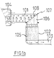
- FIGS. 1a and 1b show a first embodiment of the exhaust device according to the invention
- the exhaust manifold 101 consists of a single oblong capacity, of triangular shape in the plane of the cylinder head 104, this capacity having a single outlet opening, in its lower part, intended to be connected directly to a catalytic converter 102. Connecting the catalytic converter 102 to the manifold exhaust 101 is carried out perpendicularly, thereby obtaining a compact assembly in the engine compartment. The connection of the catalytic converter 102 with the exhaust pipe 101 forms an elbow 107 causing a change of direction of 90 ° in the burnt gases.
- the catalytic converter 102 is also connected to an exhaust line 103 comprising conventional elements such as an expansion pot and a silencer not shown in the figures.
- the catalytic converter 102 comprises a first monolithic element 105 consisting of a regular network of channels parallel to each other and arranged in the longitudinal axis of the catalytic converter 102. These channels are coated with a active catalytic substance, for example based on precious metals and metal oxide, allowing the treatment of polluting substances contained in the burnt gases.
- a second monolithic element 106 is arranged at the level of the elbow 107 formed by the connection of the manifold 101 with the catalytic converter 102.
- the second monolithic element 106 comprises, similarly to the first monolithic element 105, multiple channels oriented in the axis of the first monolithic element 105 so as to bring the gas flow in the direction thereof, these channels being able to be coated of substances active catalysts for the treatment of burnt gases.
- the inlet end 108 of the burnt gases of the second monolithic element 106 is truncated so as to have an inlet face inclined in the direction of the flow of the burnt gases.
- the inclination of this inlet end 108 is, in the example, between 15 ° and 30 ° and depends on several parameters including the diameter of the monolithic element 106 and the characteristics of the cavity forming the exhaust manifold 101.
- This inclination of the inlet end 108 makes it possible to increase the passage section, in the direction of the burnt gases, of the channels of the second monolithic element 106 and thus to obtain better filling of the latter.
- the length of the second monolithic element 106 is adapted so that the outlet face of the latter is situated approximately at the level of the inlet of the diverging portion of the catalytic converter 102.
- the substantially homogeneous distribution of the gases in the channels of the monolithic element 106 then allows the homogeneous diffusion of the burnt gases at the inlet of the diverging part of the catalytic converter 102 and therefore a homogeneous distribution of the gases in the channels of the first monolithic element 105. This arrangement allows thus optimizing the efficiency of the catalytic converter 102.
- the installation of the monolithic element 106 in the elbow 107 therefore makes it possible to reduce strongly uneven distribution of the burnt gases in the catalytic converter 102, linked to the presence of the elbow 107, and thus reduce the risks of premature aging of the catalytic converter 102.
- FIG. 2 shows a second embodiment of the exhaust device according to the invention, for an internal combustion engine comprising a turbocharger 212 interposed between an exhaust manifold, not shown in the figure, and a catalytic converter 202 similar to that of the device of FIG. 1b, arranged perpendicular to the axis of the turbocharger 212 so as to keep a compact assembly.
- the elbow 207 formed by the connection of the outlet of the turbine of the turbocharger 212 with the inlet of the catalytic converter 202 comprises a second monolithic element 206 whose function and advantages are identical to those described for the device in FIG. 1b.
- the immediate proximity of the catalytic converter 202 with the turbocharger 212 then makes it possible to maintain a temperature of the burnt gases sufficient for the correct operation of the catalytic converter 202.
- Figure 3 shows a third embodiment of the exhaust device according to the invention.
- the first monolithic element 305 of the catalytic converter 302 and the second monolithic element 306 located in the elbow 307 differ from the elements described for the first embodiment of the exhaust device according to the invention of Figure 1b.
- the inlet 310 and outlet 311 ends of the first monolithic element 305 as well as the outlet end 309 of the second monolithic element 306 are truncated parallel to the inlet end 308 of the second monolithic element 306, the inclination is chosen according to criteria similar to those described for the first embodiment of the exhaust device of Figure 1b.
- the divergent cone of the catalytic converter 302 is adapted so that its entry surface coincides with the exit end 309 of the second monolithic element 306 and that its exit surface coincides with the entry end 310 of the first element monolithic 305.
- the inclination of the inlet end 308 of the second monolithic element 306 makes it possible, as for the first embodiment of FIG. 1b, to homogenize the flow of the burnt gases in the channels of the second monolithic element 306 and therefore to homogenize the diffusion of the burnt gases at the input of the first monolithic element 305.
- the inclination of the ends of the first and second monolithic element 305 and 306 parallel to the inlet end 308 makes it possible to maintain an identical length of all the channels of the monolithic elements.
- the coefficient of pressure losses of a channel being linked to its length, the equality of the length of the channels makes it possible to obtain identical pressure drop coefficients in each channel, which is favorable for a homogeneous distribution of the gases burned in the first and second monolithic element 305 and 306.
- the inclination of the outlet end 311 of the first monolithic element 305 in the direction of the exhaust line 303 also makes it possible to make the connection of the catalytic converter 302 with the exhaust line 303 more compact by making a perpendicular connection of the exhaust line 303 on the catalytic converter 302 at the level of the space freed by the inclination of the outlet end 311.
- a second monolithic element 306 according to the exhaust device according to the invention therefore makes it possible to straighten and homogenize the flow at the outlet of an elbow and to participate in the purification of the burnt gases thanks to the catalytic substances it contains.
- the third embodiment of FIG. 3 therefore presents an optimization of the exhaust device presented in FIG. 1b.
- Figure 4 shows a fourth embodiment of the exhaust device according to the invention.
- only the second monolithic element 406 located in the elbow differs from the elements described for the first embodiment of the exhaust device of FIG. 1b.
- the monolithic element 406 used in this embodiment is a conventional monolith whose inlet faces 408 and outlet 409 are perpendicular to the axis of the monolith.
- This monolithic element 406 has the particularity of having an inlet face 408 disposed at the outlet opening of the collector 401 and in the extension of the lower face of the latter.
- the second monolithic element 406 has a length adapted so that the outlet face 409 of the latter is disposed approximately at the level of the inlet of the diverging portion of the catalytic converter 402 so as to optimize the diffusion of the exhaust gases at the outlet from the second monolithic 406.
- This embodiment while remaining less effective than the embodiments presented in FIGS. 1b to 3, makes it possible to clearly improve the diffusion of the burnt gases downstream of the first monolithic element 405 of the catalytic converter 402 compared to the diffusion obtained when the second monolithic element 406 is not present.
- This embodiment has the advantage of being industrializable with very low cost and of providing a marked improvement in the diffusion of the burnt gases through the catalytic converter and in improving the purification of the burnt gases.
Landscapes
- Engineering & Computer Science (AREA)
- Chemical & Material Sciences (AREA)
- Chemical Kinetics & Catalysis (AREA)
- Combustion & Propulsion (AREA)
- Mechanical Engineering (AREA)
- General Engineering & Computer Science (AREA)
- Health & Medical Sciences (AREA)
- Toxicology (AREA)
- Exhaust Gas After Treatment (AREA)
- Exhaust Silencers (AREA)
Applications Claiming Priority (2)
| Application Number | Priority Date | Filing Date | Title |
|---|---|---|---|
| FR9605826 | 1996-05-10 | ||
| FR9605826A FR2748518B1 (fr) | 1996-05-10 | 1996-05-10 | Dispositif d'echappement pour moteur a combustion interne |
Publications (1)
| Publication Number | Publication Date |
|---|---|
| EP0806554A1 true EP0806554A1 (de) | 1997-11-12 |
Family
ID=9492007
Family Applications (1)
| Application Number | Title | Priority Date | Filing Date |
|---|---|---|---|
| EP97400994A Withdrawn EP0806554A1 (de) | 1996-05-10 | 1997-05-02 | Auspuffanlage für Brennkraftmaschine |
Country Status (2)
| Country | Link |
|---|---|
| EP (1) | EP0806554A1 (de) |
| FR (1) | FR2748518B1 (de) |
Cited By (3)
| Publication number | Priority date | Publication date | Assignee | Title |
|---|---|---|---|---|
| FR2860035A1 (fr) * | 2003-09-19 | 2005-03-25 | Renault Sa | Ensemble d'echappement d'un moteur thermique suralimente |
| FR3060409A1 (fr) * | 2016-12-16 | 2018-06-22 | Peugeot Citroen Automobiles Sa | Organe de traitement de gaz a corps de traitement en biseau |
| EP3234315B1 (de) * | 2014-12-18 | 2019-08-28 | Renault S.A.S. | Fahrzeugantriebseinheit mit verbessertem abgasreinigungssystem |
Families Citing this family (1)
| Publication number | Priority date | Publication date | Assignee | Title |
|---|---|---|---|---|
| FR3061517A1 (fr) * | 2017-01-04 | 2018-07-06 | Peugeot Citroen Automobiles Sa | Organe de traitement de gaz a corps de traitement de gaz en biseau |
Citations (5)
| Publication number | Priority date | Publication date | Assignee | Title |
|---|---|---|---|---|
| US4182120A (en) * | 1973-03-20 | 1980-01-08 | Ethyl Corporation | Exhaust systems |
| JPS5872613A (ja) * | 1981-10-26 | 1983-04-30 | Toyota Motor Corp | 自動車エンジン用エキゾ−ストマニホルド |
| JPH0427705A (ja) * | 1990-02-26 | 1992-01-30 | Nippon Shokubai Co Ltd | ディーゼルエンジン排ガスの浄化方法 |
| US5220789A (en) * | 1991-03-05 | 1993-06-22 | Ford Motor Company | Integral unitary manifold-muffler-catalyst device |
| FR2703297A1 (fr) * | 1993-03-31 | 1994-10-07 | Ngk Insulators Ltd | Elément à structure en nid d'abeille courbe. |
-
1996
- 1996-05-10 FR FR9605826A patent/FR2748518B1/fr not_active Expired - Fee Related
-
1997
- 1997-05-02 EP EP97400994A patent/EP0806554A1/de not_active Withdrawn
Patent Citations (5)
| Publication number | Priority date | Publication date | Assignee | Title |
|---|---|---|---|---|
| US4182120A (en) * | 1973-03-20 | 1980-01-08 | Ethyl Corporation | Exhaust systems |
| JPS5872613A (ja) * | 1981-10-26 | 1983-04-30 | Toyota Motor Corp | 自動車エンジン用エキゾ−ストマニホルド |
| JPH0427705A (ja) * | 1990-02-26 | 1992-01-30 | Nippon Shokubai Co Ltd | ディーゼルエンジン排ガスの浄化方法 |
| US5220789A (en) * | 1991-03-05 | 1993-06-22 | Ford Motor Company | Integral unitary manifold-muffler-catalyst device |
| FR2703297A1 (fr) * | 1993-03-31 | 1994-10-07 | Ngk Insulators Ltd | Elément à structure en nid d'abeille courbe. |
Non-Patent Citations (2)
| Title |
|---|
| PATENT ABSTRACTS OF JAPAN vol. 007, no. 165 (M - 230) 20 July 1958 (1958-07-20) * |
| PATENT ABSTRACTS OF JAPAN vol. 016, no. 191 (M - 1245) 8 May 1992 (1992-05-08) * |
Cited By (3)
| Publication number | Priority date | Publication date | Assignee | Title |
|---|---|---|---|---|
| FR2860035A1 (fr) * | 2003-09-19 | 2005-03-25 | Renault Sa | Ensemble d'echappement d'un moteur thermique suralimente |
| EP3234315B1 (de) * | 2014-12-18 | 2019-08-28 | Renault S.A.S. | Fahrzeugantriebseinheit mit verbessertem abgasreinigungssystem |
| FR3060409A1 (fr) * | 2016-12-16 | 2018-06-22 | Peugeot Citroen Automobiles Sa | Organe de traitement de gaz a corps de traitement en biseau |
Also Published As
| Publication number | Publication date |
|---|---|
| FR2748518B1 (fr) | 1998-06-12 |
| FR2748518A1 (fr) | 1997-11-14 |
Similar Documents
| Publication | Publication Date | Title |
|---|---|---|
| EP0584350B1 (de) | Abgasleitung für eine zweitakt-brennkraftmaschine | |
| FR2620169A1 (fr) | Partie de ligne d'echappement, notamment pour moteur a combustion interne | |
| EP1036259B1 (de) | Auspuffanlage für eine brennkraftmaschine | |
| FR2744763A1 (fr) | Turbocompresseur entraine par les gaz d'echappement d'un moteur a combustion interne | |
| FR2473631A1 (fr) | Moteur a combustion interne a quatre temps | |
| FR2506837A1 (fr) | Conduit pour les gaz d'echappement a monter entre un moteur a combustion interne et un turbo-compresseur a gaz d'echappement | |
| FR2748518A1 (fr) | Dispositif d'echappement pour moteur a combustion interne | |
| FR3107304A1 (fr) | Dispositif catalytique pour traitement des gaz d’echappement d’un moteur a combustion interne | |
| EP3365547B1 (de) | Schalldämpfende vorrichtung für eine ansaugleitung | |
| FR2778207A1 (fr) | Pot catalytique et de traitement acoustique d'une ligne d'echappement a double flux | |
| FR2527686A1 (fr) | Moteur a combustion interne a plusieurs cylindres, equipe de la combinaison d'un turbo-compresseur et d'un compresseur de suralimentation a inertie | |
| FR2663986A1 (fr) | Collecteur d'echappement pour moteur a combustion interne, et moteur a combustion interne comportant un tel collecteur. | |
| FR2752880A1 (fr) | Dispositif de suralimentation pour moteur a combustion interne | |
| FR3040193B1 (fr) | Systeme de reduction catalytique selective | |
| EP0718480A1 (de) | Abgasanlage für Brennkraftmaschine | |
| FR3109606A1 (fr) | Dispositif catalytique pour traitement des gaz d’echappement d’un moteur, comportant un organe d’injection d’air | |
| FR2545875A1 (fr) | Systeme d'echappement d'un moteur a combustion interne a turbocompresseur | |
| FR2859238A1 (fr) | Dispositif de regulation thermique de gaz d'echappement | |
| EP3827161A1 (de) | Wärmedämmvorrichtung für den auspuff einer wärmekraftmaschine | |
| FR2738289A1 (fr) | Dispositif d'echappement pour moteur a combustion interne | |
| FR2851789A1 (fr) | Moteur a combustion interne de vehicule automobile | |
| FR2727466A1 (fr) | Collecteur d'echappement pour moteur a combustion interne | |
| EP0380407A1 (de) | Auspuffkrümmer für eine aufgeladene innere Brennkraftmaschine | |
| FR2860035A1 (fr) | Ensemble d'echappement d'un moteur thermique suralimente | |
| EP0592258A1 (de) | Abgasvorrichtung für Brennkraftmaschinen |
Legal Events
| Date | Code | Title | Description |
|---|---|---|---|
| PUAI | Public reference made under article 153(3) epc to a published international application that has entered the european phase |
Free format text: ORIGINAL CODE: 0009012 |
|
| AK | Designated contracting states |
Kind code of ref document: A1 Designated state(s): DE ES GB IT |
|
| 17P | Request for examination filed |
Effective date: 19980421 |
|
| GRAG | Despatch of communication of intention to grant |
Free format text: ORIGINAL CODE: EPIDOS AGRA |
|
| 17Q | First examination report despatched |
Effective date: 20001010 |
|
| STAA | Information on the status of an ep patent application or granted ep patent |
Free format text: STATUS: THE APPLICATION HAS BEEN WITHDRAWN |
|
| 18W | Application withdrawn |
Withdrawal date: 20010216 |