EP0806610A2 - Procédé et dispositif pour le fonctionnement d'un brûleur à gaz - Google Patents
Procédé et dispositif pour le fonctionnement d'un brûleur à gaz Download PDFInfo
- Publication number
- EP0806610A2 EP0806610A2 EP97105850A EP97105850A EP0806610A2 EP 0806610 A2 EP0806610 A2 EP 0806610A2 EP 97105850 A EP97105850 A EP 97105850A EP 97105850 A EP97105850 A EP 97105850A EP 0806610 A2 EP0806610 A2 EP 0806610A2
- Authority
- EP
- European Patent Office
- Prior art keywords
- signal
- gas
- ionization
- burner
- control
- Prior art date
- Legal status (The legal status is an assumption and is not a legal conclusion. Google has not performed a legal analysis and makes no representation as to the accuracy of the status listed.)
- Granted
Links
Images


Classifications
-
- F—MECHANICAL ENGINEERING; LIGHTING; HEATING; WEAPONS; BLASTING
- F23—COMBUSTION APPARATUS; COMBUSTION PROCESSES
- F23N—REGULATING OR CONTROLLING COMBUSTION
- F23N1/00—Regulating fuel supply
- F23N1/02—Regulating fuel supply conjointly with air supply
- F23N1/022—Regulating fuel supply conjointly with air supply using electronic means
-
- F—MECHANICAL ENGINEERING; LIGHTING; HEATING; WEAPONS; BLASTING
- F23—COMBUSTION APPARATUS; COMBUSTION PROCESSES
- F23N—REGULATING OR CONTROLLING COMBUSTION
- F23N5/00—Systems for controlling combustion
- F23N5/02—Systems for controlling combustion using devices responsive to thermal changes or to thermal expansion of a medium
- F23N5/12—Systems for controlling combustion using devices responsive to thermal changes or to thermal expansion of a medium using ionisation-sensitive elements, i.e. flame rods
- F23N5/123—Systems for controlling combustion using devices responsive to thermal changes or to thermal expansion of a medium using ionisation-sensitive elements, i.e. flame rods using electronic means
-
- F—MECHANICAL ENGINEERING; LIGHTING; HEATING; WEAPONS; BLASTING
- F23—COMBUSTION APPARATUS; COMBUSTION PROCESSES
- F23N—REGULATING OR CONTROLLING COMBUSTION
- F23N2225/00—Measuring
- F23N2225/26—Measuring humidity
- F23N2225/30—Measuring humidity measuring lambda
-
- F—MECHANICAL ENGINEERING; LIGHTING; HEATING; WEAPONS; BLASTING
- F23—COMBUSTION APPARATUS; COMBUSTION PROCESSES
- F23N—REGULATING OR CONTROLLING COMBUSTION
- F23N2227/00—Ignition or checking
- F23N2227/20—Calibrating devices
-
- F—MECHANICAL ENGINEERING; LIGHTING; HEATING; WEAPONS; BLASTING
- F23—COMBUSTION APPARATUS; COMBUSTION PROCESSES
- F23N—REGULATING OR CONTROLLING COMBUSTION
- F23N2231/00—Fail safe
- F23N2231/30—Representation of working time
-
- F—MECHANICAL ENGINEERING; LIGHTING; HEATING; WEAPONS; BLASTING
- F23—COMBUSTION APPARATUS; COMBUSTION PROCESSES
- F23N—REGULATING OR CONTROLLING COMBUSTION
- F23N2233/00—Ventilators
- F23N2233/06—Ventilators at the air intake
- F23N2233/08—Ventilators at the air intake with variable speed
-
- F—MECHANICAL ENGINEERING; LIGHTING; HEATING; WEAPONS; BLASTING
- F23—COMBUSTION APPARATUS; COMBUSTION PROCESSES
- F23N—REGULATING OR CONTROLLING COMBUSTION
- F23N2235/00—Valves, nozzles or pumps
- F23N2235/12—Fuel valves
- F23N2235/16—Fuel valves variable flow or proportional valves
Definitions
- the invention relates to a method and a device for operating a gas burner with the features of the preamble of patent claim 1.
- gas appliances have to meet high safety requirements.
- safety regulations EN 298
- the flame monitor in gas devices for continuous operation during operation runs through a self-check at regular intervals, at least once an hour.
- the gas burner must switch off at least once within 24 hours in order to be able to check the function of the flame detector. It cannot be ruled out that the flame monitor will malfunction during burner operation and that the flame will also go out.
- the burner control cannot recognize this at first and cannot trigger a gas shutdown signal, which means that unburned gas flows out until the next self-check of the flame monitor or the burner is switched off.
- An ionization flame monitor is known from DE 43 09 454 A1, in which a capacitor charged to an operating voltage is discharged by the ionization current. During operation, the function of the ionization flame monitor can be checked using a test signal will. The ionization electrode itself and its connection cable as well as the capacitor in certain malfunctions cannot be checked. The flame is only monitored indirectly. In addition, the flame monitor is only checked by the test signal in periodically recurring periods.
- the object of the invention is to propose an improved method and a device of the type mentioned at the outset in order to ensure low-emission combustion in various operating states.
- the above object is achieved by the features of the characterizing part of claim 1. It is thereby achieved that the gas burner can be operated with low emissions at least in the Wobbeiere range of natural gas (10 kWh / m 3 to 15.6 kWh / m 3 ). It is also achieved that the control does not undesirably influence the desired heat output to be provided by the gas heater working with the gas burner, so that the gas heater can cover the heat requirement with the requested heat output.
- a further embodiment (cf. FIGS. 9, 10) of the method deals with the following problems:
- the control circuit regulates the gas quantity valve in dependence on the ionization signal in such a way that the combustion takes place with a desired lambda value> 1, in particular between 1.1 and 1.35, for low-emission operation.
- the control circuit itself does not serve for the heat demand-dependent power adjustment.
- the heating output of the burner is adjusted in a manner known per se by means of the control unit which adjusts the blower fan speed in two or more stages or continuously. In the event of rapid changes in the power setpoint and accordingly Rapid changes in the fan speed can lead to sudden control deviations in the control circuit. This could lead to instabilities in the control circuit.
- the reserve component for the control signal of the gas quantity valve is derived from the change in speed independently of the control circuit or in parallel to it.
- the control circuit then only has to make a fine control with a comparatively small control deviation.
- the reserve portion of the control signal is easy to obtain because the device-specific power control signal characteristic is known by the manufacturer and can therefore be stored in the evaluation circuit.
- the control signal for the gas quantity valve is adjusted - independently of the control circuit - by the reserve portion which changes this. If the output increases, the gas quantity valve is opened further; if the output is reduced, the gas quantity valve is closed further.
- the control circuit itself then only needs to make a fine adjustment to the lambda setpoint. So you do not have to process large, erratic control deviations based on the change in performance.
- a tolerance band is preferably defined around the power control signal characteristic curve and a switch-off signal for the burner is generated when the actual control signal leaves the tolerance band.
- the tolerance band is dimensioned such that it is not left during normal operation of the gas blower burner of the gas heater and is left if, during the operation of the gas heater, characteristics of the sensors, especially the ionization electrode and / or the measured value recording, or the actuators, especially the Gas quantity valve or Change the airway of the fan or the exhaust gas path or the burner, for example due to contamination.
- the tolerance band will also be left in the event of strongly fluctuating gas wobble numbers, strongly fluctuating gas connection pressure or fluctuating air resistances or in the event of malfunctions in the control system. In all such cases, a shutdown signal is generated for the burner so that it does not continue to work in an area which is unfavorable for low-emission combustion.
- This switch-off signal can take effect immediately or preferably when the tolerance band has been left for a certain period of time, for example 5 s. This ensures safe and low-emission operation of the burner even after many hours of operation.
- the control circuit itself can also generate switch-off signals if the specified lambda target value cannot be maintained.
- control unit switches on the gas fan burner again. If the shutdown signal then occurs several times, a lockout can be provided, after which the gas fan burner can only be switched on again by service measures. By defining the tolerance band, other, previously customary safety devices can be dispensed with.
- the tolerance band can be set symmetrically or asymmetrically or according to a desired function in relation to the power control signal characteristic.
- FIGS. 11 to 14 Another or additional configuration (see FIGS. 11 to 14) is intended to ensure that a gas cut-off signal occurs both when the flame does not exist and also occurs when there is a defect which is deceptive to the ionization signal produces a similar signal, such a defect may be present on the entire functional path from the ionization electrode to a monitoring circuit.
- a characteristic flame pattern that influences the ionization signal is used for monitoring.
- the fluctuations in the flame intensity are exploited, the fluctuations occurring due to the inevitable flickering of the flame image due to combustion being evaluated, and fluctuations modulated in a targeted manner being evaluated in the other version of the flame.
- Amplitude fluctuations are preferably evaluated.
- the phase or frequency can also be evaluated, especially in the case of targeted modulation instead or in addition.
- the gas cut-off signal which blocks the gas supply, does not only occur when the flame goes out. It also occurs when there is a signal that is deceptively similar to the real ionization signal due to some technical defect.
- the gas shutdown signal only occurs when the characteristic fluctuations in the flame pattern and therefore the ionization signal derived therefrom are not available. A technical defect in the device, which simulates the characteristic fluctuations in the flame pattern, is excluded in practice.
- the entire functional path from the ionization electrode to the evaluation circuit is monitored by the method.
- the gas cut-off signal therefore occurs regardless of whether the defect simulating the ionization signal is in the ionization electrode itself or its connecting line or the monitoring circuit or elsewhere in the system. This makes it a very high one System security achieved that even goes beyond the previous security regulations.
- the safety flame monitoring is also carried out continuously with regard to monitoring for technical defects during burner operation, i.e. with a burning flame. So it can not happen that after a defect there is a longer period in which unburned gas flows out. In the case of the modulation deliberately impressed on the flame, it may be sufficient if the modulation signal is generated periodically, the time between two successive modulation signals being so short that, in the event of a defect, no dangerous amount of gas flows out unburned during this time.
- the ionization signal does not have to be generated alone or separately for the safety flame monitoring. It can also serve to control the combustion, which is described in DE 44 33 425 A1 or DE 195 02 901 C1.
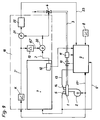
- a blower (2) and a gas line (3) are connected to a burner (1) of a gas heater Gas solenoid valve (4) or another gas control valve is located.
- An ionization electrode (5) is arranged in the flame area of the burner (1) and is connected to an evaluation circuit (6) for the current flowing between the burner (1) and the ionization electrode (5) during burner operation.
- the evaluation circuit (6) has in particular a capacitor (C) connected to the AC line voltage and a resistor (R).
- the evaluation circuit (6) forms an ionization voltage (Ui) from the ionization current, which is dependent on the combustion, and is applied to a control circuit (7).
- the evaluation circuit (6) can also be integrated in the control circuit (7).
- the control circuit (7) controls the degree of opening of the gas solenoid valve (4) by means of a control signal (J), in particular control current.
- the mains AC voltage is applied to the control circuit (7) for the voltage supply. It also records the network frequency and the network amplitude.
- the control circuit (7) is, for example, by a digital PI controller, e.g. Microprocessor, realized.
- An automatic control unit (9) is provided for two-stage or multi-stage control of the fan speed, as is known on the market, for example, under the trade name "Furimat”.
- a safety valve (10) can be switched on and off by means of the automatic control unit (9), whereas the gas solenoid valve (4) allows the gas volume flow to be set continuously.
- a setpoint generator (8) is connected to the automatic control unit (9) and sends a signal to the automatic control unit (9) that is dependent on a set room temperature and / or a heating flow temperature and / or a heating return temperature and an outside temperature.
- gas pressure switch (11) which switches off the combustion mode when the gas pressure is insufficient via the control unit (9).
- a gas pressure switch (11) is integrated in the control circuit (7), a switch (12) which interrupts the burning operation via the control unit (9) in the case of the control shutdowns described below and the fault shutdowns.
- the automatic control unit (9) sends an ignition pulse to an ignition electrode (14) of the burner (1) each time it is switched on.
- the ionization electrode (5) is connected to the control unit (9) (line 15). This is tapped at the safety valve (10) operated with the mains voltage and connected to the control circuit (7) (line 16).
- a speed control signal of the blower (2) is connected to the control unit (9) and the control circuit (7) via a line (17).
- the evaluation circuit (6), the control circuit (7) and the automatic control unit (9) can also be integrated in a single switching device.
- the device according to FIG. 1 is advantageous because the proven automatic control unit (9) with its control and safety functions for the burner (1) and the blower (2) can continue to be used.
- the control circuit (7) only needs to control the gas solenoid valve (4).
- the switch-off signals generated by it are evaluated by the automatic control unit (9). It is possible to retrofit existing gas heaters with the control automats (9) with the control circuit (7).
- FIG. 2a shows the evaluation circuit (6), the ionization electrode (5) with its equivalent circuit diagram being represented as a resistor (Ri) and diode (D).
- a voltage divider made up of resistors (R1, R2) lies parallel to the ionization electrode (5 or Ri, D).
- the capacitor (C) is located between the mains connection (N) and the voltage divider (R1, R2) and the ionization electrode (5; Ri, D).
- the AC mains voltage (Un) shifts by a DC voltage component (Ug) to the voltage (Ub) (see Fig. 2b), which is recorded as Uc via the voltage divider (R1, R2).
- the DC voltage component (Ug) is then filtered out by means of a low-pass filter or by averaging and forms the ionization voltage (Ui).
- the low pass or devices for averaging are not shown in the figures. They can be provided in the evaluation circuit (6) or in the control circuit (7).
- the use of the AC line voltage at the evaluation circuit (6) is favorable because the AC line voltage is present anyway. However, another sufficiently large AC voltage could also be used.
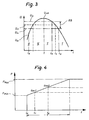
- FIG. 3 shows the course of the ionization voltage as a function of the air ratio lambda (l) of the combustion state.
- substoichiometric combustion (l ⁇ 1) and with stoichiometric combustion (l> 1) the ionization voltage (Ui) drops.
- a lambda target value (ls> 1) between 1.1 and 1.35, for example 1.15, is desirable. This corresponds to an ionization voltage setpoint (Uis) (see FIG. 3).
- An approved control range (RB) for the ionization voltage (Ui) with an upper limit value (Uio) and a lower limit value (Uiu) is specified in the control circuit (7).
- the upper limit (Uio) is below the maximum value (Uim).
- the lower limit value (Uiu) lies above the final value (Uie), which arises when the lambda value (l) is very much less than 1, ie the air / gas mixture because of maximum Gas supply or minimal air supply is so rich that the combustion is no longer low in emissions.
- the ionization voltage (Ui) is newly acquired at very short time intervals, for example every 50 to 1000 ms, preferably about 100 ms. It is thus achieved that the ionization voltage (Ui) can never lie outside the control range (RB) for a long time, which ensures low-emission combustion as seen over each combustion process.
- the values of the ionization voltage (Ui) move within the permitted control range, that is between Uio and Uiu, so that the lambda value (l) is regulated accordingly in the range (lo to lu) to the lambda setpoint (ls).
- the control circuit (7) opens the gas solenoid valve (4) further via the control signal (J), whereby the combustion is controlled in the direction of the lambda setpoint (ls). If the ionization voltage setpoint (Uis) is exceeded, the control circuit (7) controls the gas solenoid valve (4) in such a way that the gas supply is reduced, as a result of which the lambda value is regulated again to the lambda setpoint (ls). This applies to the control range (RB) and also to combustion conditions outside the control range (RB).
- the control circuit (7) activates a timer, which can also be implemented in the control circuit itself.
- the gas solenoid valve (4) is opened further in order to again reach the lambda setpoint (ls). If the ionization voltage (Ui) returns to the control range (RB) within the time period specified by the timer, for example 3 s to 10 s, in particular 5 s, then nothing else happens.
- the burner (1) continues to run and the timer is reset.
- a switch-off signal for the burner (1) is generated by opening the switch (12).
- the burner (1) is switched off as a rule.
- the burner (1) is restarted a short time after the control shutdown, for example 5 to 50 s. If such a control shutdown then occurs several times, for example three times in succession, the burner (1) is no longer restarted automatically, but instead a fault lockout is carried out and displayed by keeping the switch (12) open, which can only be achieved by a special intervention by can be picked up outside.
- a shutdown signal for the burner occurs again. This is restarted after a delay time and, as described above, a fault lock-out occurs when the switch-off signal occurs again.
- the control circuit (7) If the maximum value of the control signal is reached, this is detected by the control circuit (7) and activates a shutdown signal for the burner. This does not have to switch off the burner immediately. It is also sufficient if the burner is only switched off with a delay time predetermined by a further timer, for example 5 s. This is cheap for the following reason: It is not excluded that the gas solenoid valve (4) initially jams when the modulation current (J), which is the control signal, increases, so that the modulation current adopts its maximum value, but the gas solenoid valve does not open any further. The gas solenoid valve (4) has time to start up within the delay time, and if it does so, unnecessary shutdown of the burner is avoided.
- J modulation current
- the occurrence of the minimum value of the control signal (J) is also recorded electronically and evaluated for a control shutdown. This ensures that the burner (1) is switched off when the minimum value of the control signal (J) has been reached, but the gas solenoid valve (4) does not close for some reason.
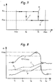
- a starting gas ramp is specified (see Fig. 4), after which in a Safety time (T) by activating the gas flow valve (4) each time the burner (1) is started, the gas pressure or gas volume flow is continuously increased from pmin to pmax.
- pmin and pmax are dimensioned so that the burner starts reliably with every Wobbe number of the gas family in question, for example natural gas.
- the fan (2) starts up at a constant speed.
- the gas solenoid valve (4) is increasingly opened at time (t0).
- the optimum gas-air mixture is reached at time (t1) (gas 1), so that the ignition takes place.
- the corresponding gas solenoid valve position is maintained at the end of the safety time (T). Only then does the regulation described above apply.
- the ignitable mixture is only reached, for example, at time (t2). The ignition then takes place and this gas solenoid valve position is maintained until the end of the safety time (T). With each Wobbe number of the respective gas, the ignition is guaranteed.
- the control circuit (7) works as a, preferably digital, PI controller which detects the ionization voltage with a sampling period of, for example, the above-mentioned 100 ms and calculates the new value for the control signal (J) at the same frequency.
- the respective control signal change (dJ) is made up of the changes caused by the I control part and the P control part changed compared to the last control value.
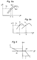
- a smaller control signal (J1) is required for a higher calorific gas with the same ionization voltage setpoint (Uis) (gas 1 in FIG. 5a) than for a low calorific gas (gas 2 in FIG. 5a).
- the higher control signal (J2) is required for Uis (see Fig.5a). The control circuit takes this into account.
- the situation is similar if the burner (1) is to be operated in a power level (S1) of higher power and in a power level (S2) of lower power by appropriately setting the fan speed (see Fig. 5b).
- the control circuit (7) detects the fan speed or determines the load from the position of the connected gas solenoid valve (4) via line (17) and, with the same ionization voltage setpoint (Uis), sets higher values of the control signal (J ) than in the lower power level (S2) (see Fig.5b).
- FIG. 6 shows the control signal change (dJ) as a function of the control deviation (d) of the respective ionization voltage (Ui) from the target ionization voltage (Uis). It can be seen that with positive and negative control deviations (d) of the same size, the control signal change (dJ) with positive control deviations (above dp1) is greater than with the same negative control deviations (below dn1). FIG. 6 also shows that the P control component only becomes active from a certain positive or negative control deviation (dp1, dn1). There is no control signal change (dJ) between the control deviations (dn1 and dp1).
- control signal (J) is not constantly changed in the inevitable scatter of the measured values of the ionization voltage (Ui) and thus the gas solenoid valve (4) does not change with every control deviation, however small or short, due to the low-emission Operation of the burner is practically without influence, is adjusted.
- the P control component is shown in dotted lines in FIG. 6.
- the I control component is indicated by a solid line. In the event of negative system deviations, the I control component at a longer reset time than with positive control deviations.
- An alternating current for example with the mains frequency, is superimposed on the modulation current (J) by the control circuit (7).
- the amplitude of the superimposed AC component is substantially smaller than the control signal (J) as such, which is between 30 mA and 150 mA, for example.
- the superimposed AC component reduces the valve hysteresis caused by the mechanical structure of the gas solenoid valve (4), so that the gas solenoid valve (4) responds quickly to control signal changes (dJ) in both directions.
- the control circuit lowers the ionization voltage setpoint (Uis) for a limited time.
- Threshold values (J1, J2) for the control signal (J) are specified in the control circuit (7).
- the control circuit (7) If low-calorific gas occurs at the ionization voltage setpoint (Uis), which can lead to a control shutdown of the combustion, the control circuit (7) first increases the control signal (J) in the manner described to increase the gas supply accordingly. However, if the upper threshold value (J1) is reached, then the control circuit (7) lowers the ionization voltage setpoint to Uisn (a in FIG. 7). Although this involves a slight increase in the lambda value, it is ensured that the burner (1) continues to burn. The Control signal (J) will then decrease again in the direction of the lower threshold value (J2) if the gas does not become even lower calorific (arrow b in FIG. 7), which would lead to a control shutdown or to a lockout. If the lower threshold value (J2) is then reached, the control circuit (7) (cf. c in FIG. 7) switches back to the original ionization voltage setpoint (Uis).
- a calibration function is therefore integrated in the control circuit (7).
- the calibration function is activated at regular intervals, by an event counter, for example a counter of the switch-on or switch-off processes, or by an operating hours counter.
- the described control function is switched off during calibration.
- the calibration is preferably carried out when the speed of the fan (2) does not change in order to suppress the influence of the fan (2) on the combustion.
- the calibration can also take place during the switching of the fan (2) from one power level to the other power level, since the change in speed is slow compared to the calibration process, so that the speed during the calibration process is quasi constant.
- the calibration process is started at time (t1) (see Fig. 8) by the event or operating hours counter during the transition from the full load stage to the partial load stage of the blower (2) when the decreasing modulation current (J) reached a low value (Jk). This value is saved by the control circuit.
- the control circuit (7) then increases the modulation current (J) and thus the gas supply via the gas solenoid valve (4), as a result of which the ionization voltage (Ui) increases accordingly.
- the ionization voltage (Ui) reaches a predetermined value, for example 0.9 Uimax.
- the time period (t1 to t2) serves to start the preheating of the ionization electrode (5). From time (t2) up to time (t3) the modulation current (J) is kept constant. During this period (t2 to t3), the ionization electrode (5) heats up to a stable temperature and thus ensures reproducible measured values.
- the modulation current (J) is increased further by the control circuit (7) in such a way that the maximum value (Uimax) of the ionization voltage (Ui) is exceeded.
- This - new - maximum value (Uimax) and / or the measured values resulting in the time period (t3 to t4) is / are stored for further processing in the calibration process.
- the modulation current (J) is increased further until the ionization voltage (Ui) is again approximately 10% below the Uimax value, which is the case in FIG. 8 at time (t4).
- the lambda value of the combustion itself is unfavorable, but this is not important since this period lasts at most a few seconds.
- the control circuit (7) switches back to the control process described above, taking into account the previously stored modulation current (JK). This starts when the ionization voltage (Ui), the modulation current (J) and the gas pressure (p) have stabilized at time (t5).
- the control circuit (7) derives a correspondingly adapted new setpoint for the ionization voltage (Uis) from the stored - new - maximum value of the ionization voltage or from the measured values obtained in the period (t3 to t4).
- an average can be formed between the new measurement series and the measurement series of previous calibration processes.
- the first transfer criterion detects a sudden change in all components of the control loop. It is fulfilled if the deviation of the new calibration value from the previous calibration values is sufficiently small.
- the second transfer criterion detects a "creeping drift" of the system (burner control), which is sufficiently small in the event of a deviation from the values provided by the manufacturer.
- the burner operation will only continue with the recalibration if both transfer criteria are met. Is If one of the transfer criteria is not met, the burner operation is initially interrupted by a control shutdown and after repeated repetition by a lockout.
- the control unit (9) switches the safety valve (10) and the blower (2) in the usual way depending on the heat requirement and the gas pressure ("normal control shutdown").
- the automatic control unit (9) switches the burner (1) on again.
- the repeated shutdowns are recorded by counters.
- the counters for the control shutdown a, b, or fault shutdowns f, g, are reset by each "normal control shutdown" of the control unit (9).
- the counter for the control shutdowns c, d, e, or lockout h, is reset when the calibration is valid.
- the lockout can also be initiated by the control circuit (7) closing the gas solenoid valve (4) by means of the minimum value of the control signal (J).
- the contact of the gas pressure switch (11) initially remains closed.
- the automatic control unit (9) determines that the burner flame is extinguished via the line (15), whereupon it closes the safety valve (10).
- the automatic control unit (9) then tries to ignite the burner (1) again, the safety valve (10) being connected to the mains voltage, which is thereby also transmitted to the control circuit (7) via the line (16).
- the ignition attempt cannot succeed because the gas solenoid valve (4) is closed.
- the automatic control unit (9) goes to "fault" and reports "no ignition possible".
- the control circuit (7) counts the ignition attempts of the automatic control unit (9) and then opens after a certain time, for example 10s after the end of the fourth Try the switch (12) so that the control unit (9) now also closes the safety valve (10) for safety. A high level of operational reliability is thus achieved, the security features present in the automatic control unit (9) being used.
- a blower (2) and a gas line (3), in which a gas solenoid valve (4) is located as a gas quantity valve, are connected to a burner (1) of a gas heater.
- An ionization electrode (5) which is connected to a control circuit (7), is arranged in the flame area of the burner (1).
- the signal from the ionization electrode (5) is also connected to the burner control (9) described in more detail below via the line (6 '). In the burner control unit (9) it is possible to monitor the burner (1) for the presence or absence of a flame.
- the control circuit (7) controls the degree of opening of the gas solenoid valve (4) as a function of a current flowing in the combustion mode via the ionization electrode (5) and a preset lambda setpoint by means of a control signal (J), especially control current.
- the control circuit (7) is, for example, a digital PI controller, which is implemented, for example, by a microprocessor.
- the control circuit (7) ensures low-emission combustion, for example with a lambda setpoint between 1.1 and 1.35, preferably at 1.15.
- An automatic control unit (9) is provided for two-stage or multi-stage or for the stepless control of the fan speed, as is known on the market, for example, under the trade name "Furimat”.
- a safety valve (10) can be switched on and off by means of the automatic control unit (9), whereas the gas volume flow can be switched on with the gas solenoid valve (4) is continuously adjustable.
- a setpoint generator (8) is connected to the automatic control unit (9) and sends a signal to the automatic control unit (9) that is dependent on a set room temperature and / or a heating flow temperature and / or a heating return temperature and an outside temperature.
- a switch (12) is integrated in the control circuit (7) and interrupts the burning operation via the control automat (9) if the desired lambda setpoint cannot be guaranteed.
- the automatic control unit (9) Via a line (13), the automatic control unit (9) sends an ignition pulse to an ignition electrode (14) of the burner (1) each time it is switched on.
- a signal determining the speed of the fan (2) is applied by the automatic control unit (9) via a line (17 ') to the fan (2) on the one hand and to an evaluation circuit (18) on the other.
- the device-specific speed, ie, power control signal, characteristic curve (K) is stored in the evaluation circuit (18).
- This characteristic curve - regardless of the respective setting of the control circuit (7) - represents the relationship between the degree of opening of the gas solenoid valve (4) required at a respective fan speed to achieve the desired burner output.
- the evaluation circuit (18) generates according to the characteristic curve (K) a reference signal (J '). In a circuit part (19) it detects the change in the reference signal (J ') against the previous state. This change (dJ ') corresponding to the change in the rotational speed impresses it positively or negatively on an adder (20) as a reserve component to the control signal (J). As a result, the control signal (J) is adjusted in accordance with the change in speed in parallel with the control circuit (7) to the desired output or the fan speed.
- the gas solenoid valve (4) is opened or closed further by an amount approximately corresponding to the desired change in output.
- the control circuit (7) therefore does not have to process the desired change in performance itself. With the respective power setting, it regulates the gas solenoid valve (4) to the lambda setpoint required for low-emission combustion.
- the reference signal (J ') and the control signal (J) changed by the reserve component (dJ') are applied to a comparator (21). This is connected to a correlator (22) in which a tolerance band with an upper tolerance limit (To) and a lower tolerance limit (Tu) is stored (cf. FIG. 2).
- the correlator (22) detects whether the respective value is still within the tolerance band (To, Tu) or has moved outside the tolerance band. If the respective value of the control signal (J) changed by the reserve component (dJ ') has moved from the tolerance band around the characteristic curve (K), then this is a sign that due to any malfunctions, low-emission combustion is no longer guaranteed to the desired extent .
- the correlator (22) gives a switch-off signal via the line (23) to the control unit (9) in the event of such faults. This does not have to take place at the beginning of the fault. It is preferably only switched off when the fault lasts for a certain time, for example 5 seconds.
- the automatic control unit (9) starts the burner (1) again after a certain time after being switched off. If the shutdown signal from the correlator (22) then occurs several times, for example three times, then the automatic control unit (9) is switched to malfunction, so that the burner (1) can only be switched on again by service personnel.
- the functions of the evaluation circuit (18) with the storage of the characteristic curve (K), the circuit part (19), the adder (20), the comparator (21) and the correlator (22) can be implemented in a microprocessor, which is also the Functions of the control circuit (7) takes over.
- the characteristic curve (K) is shown in FIG. 10, the fan I (2) running at a speed (D1) for a low power level at point I thereof. In the ideal case, this corresponds to a control signal reference signal (J'1) without the readjustment required by the control circuit (7). At a higher speed (D2) for a larger power level, the characteristic curve (K) (see point II) gives a reference signal (J'2).
- the characteristic curve (K) runs essentially linearly between points I and II. However, this does not necessarily have to be the case, rather it can also have a kinking curve.
- the tolerance band with its upper tolerance limit (To) and its lower tolerance limit (Tu) lies above and below the characteristic curve (K).
- the control range to be controlled by the control circuit (7) lies within the tolerance limits.
- the tolerance band does not have to run symmetrically to the characteristic (K). Depending on the specific properties of the device, it can also be asymmetrical or spread, or it can also be defined according to special functions.
- the correlator (22) does not initiate a shutdown signal. However, if this value comes at the speed (D1) or the speed (D2) or an intermediate speed outside the tolerance band, the shutdown signal is initiated.
- a gas line (3) is connected to a gas burner (1) for a gas heater and contains a gas valve (4), for example a solenoid valve, which can be switched off and regulated.
- a gas valve (4) for example a solenoid valve, which can be switched off and regulated.
- An air connection (2 ') and optionally an air-promoting, speed-controllable fan (2) are arranged on the gas burner (1).
- the blower (2) is not necessary in every case; it can also be an atmospheric gas burner.
- An ionization electrode (5) protrudes into the flame area of the gas burner (1).
- An AC voltage preferably the AC mains voltage (U) is applied to the ionization electrode (5) via a capacitive coupling element (27).
- the coupling element (27) consists of a capacitor and a resistor.
- the coupling element (27) is electrically connected to earth via a resistor (28), like the gas burner (1).
- a voltage divider (29) is connected to the ionization electrode (5) and reduces the voltage that occurs, for example by a factor of 10.
- a filter (210) is connected to the voltage divider (29), which filters out the frequency of the coupled AC voltage (50 Hz).
- an ionization signal (ionization voltage Uio) is present at the output (211) of the filter (210), as is shown, for example, in FIG.
- the ionization signal fluctuates around an average value (M) in accordance with the inevitably occurring flickering of the flames (fluctuations in the flame intensity).
- weaker fluctuations which are indicated by the bandwidth (S1) in FIG. 12, and stronger fluctuations, which are represented by the bandwidth (S2) in FIG. 12, occur in succession.
- FIG. 12 shows, by way of example, a decreasing course of the mean value (M) over time, which results from a change in the excess air (lambda value) of the respective combustion process and which is proportional to the respective lambda value.
- first function block (212) which rectifies or filters out the fluctuations caused by the flickering in such a way that the above-mentioned mean value (M) is available at the output (213) of the first function block (212).
- the output (213) of the first function block (212) is followed by a second function block (214) which generates an amplitude tolerance band around the mean value (M), the width of which is denoted by B in FIG.
- the tolerance bandwidth (B) is dimensioned such that it is smaller than the smallest bandwidth (S1) of the fluctuations.
- the output (215) of the function block (214) is connected to a comparator function block (216), on which the output (211) is also located.
- the comparator function block (216) is located at a reset input of a timer (217), which acts on a control device (218) for the gas valve (4).
- a control device (218) is common as an "automatic burner control".
- control device (218) only has to convert the output signal of the timer (217) into a switch-off signal for the gas valve (4).
- the comparator function block (216) constantly compares whether an amplitude fluctuation occurs in the ionization signal (Uio) that exceeds or falls below the amplitude tolerance band (B). If such an amplitude fluctuation occurs, the comparator function block (216) sends a reset signal to the timer (217).
- the timer (217) is set to zero by each reset signal of the comparator function block (216) and then starts counting again and again. If the time period preset on the timer (217), for example 5 s, has expired and no reset signal has occurred in this time period, then the timer (217) sends a gas cut-off signal to the control device (218), which then closes the gas valve (4).
- the period of time mentioned is set such that an amplitude fluctuation of the ionization signal occurs reliably in the regular, undisturbed burner operation. In order not to make the sensitivity too high, it can also be provided that the gas valve is only switched off when some, for example two or three, gas cut-off signals follow one another.
- FIG. 11 there is a control circuit (219 or 7) at the output (213), as described, for example, in DE 44 33 425 A1.
- the gas valve (4) and / or the blower (2) is regulated in such a way that, with different gas qualities and different environmental conditions, optimal combustion results with a desired lambda setpoint.
- control circuit (219) and the described components (29 to 217) can be implemented in a microcontroller or microprocessor. The effort for the safety flame monitoring is therefore low.
- Figure 14 shows another embodiment schematically. Parts corresponding to FIG. 11 are provided with the reference numerals there.
- a modulator (220) is connected to the gas valve (4). This modulates the gas supply to the gas burner (1) so that there are fluctuations in the flame intensity. Such targeted fluctuations in the flame intensity can also be achieved by specifically modulating the air supply, for example by means of the blower (2) (see FIG. 11).
- a demodulator (221) tuned to the modulator (220) detects these characteristic fluctuations.
- a flame monitoring circuit (222) connected to the demodulator (221) monitors whether the fluctuations generated by the modulator (220) occur in the demodulator (221) and gives a gas cut-off signal via the modulator (220) or directly to the gas valve (4) if the Fluctuations are not recognized by the demodulator (221).
- the modulation can take place continuously or periodically, for example every 5 s to 10 s, for a short time, for example 1 s to 3 s. Periodic modulation ensures that, seen over the burning time, the modulation has only a slight influence on the lambda value of the combustion process.
- control circuit (219 or 7) is not shown in Figure 14. It can also be present in this embodiment. If the control circuit works with a microprocessor or microcontroller, then the function of the safety flame monitoring can also be easily integrated into this embodiment.
Landscapes
- Engineering & Computer Science (AREA)
- Chemical & Material Sciences (AREA)
- Combustion & Propulsion (AREA)
- Mechanical Engineering (AREA)
- General Engineering & Computer Science (AREA)
- Regulation And Control Of Combustion (AREA)
- Control Of Combustion (AREA)
- Feeding And Controlling Fuel (AREA)
- Gas Burners (AREA)
Applications Claiming Priority (6)
| Application Number | Priority Date | Filing Date | Title |
|---|---|---|---|
| DE19618573A DE19618573C1 (de) | 1996-05-09 | 1996-05-09 | Verfahren und Einrichtung zum Betrieb eines Gasbrenners |
| DE19618573 | 1996-05-09 | ||
| DE19627857 | 1996-07-11 | ||
| DE19627857A DE19627857C2 (de) | 1996-07-11 | 1996-07-11 | Verfahren zum Betrieb eines Gasgebläsebrenners |
| DE19631821 | 1996-08-07 | ||
| DE19631821A DE19631821C2 (de) | 1996-08-07 | 1996-08-07 | Verfahren und Einrichtung zur Sicherheits-Flammenüberwachung bei einem Gasbrenner |
Publications (3)
| Publication Number | Publication Date |
|---|---|
| EP0806610A2 true EP0806610A2 (fr) | 1997-11-12 |
| EP0806610A3 EP0806610A3 (fr) | 1998-04-15 |
| EP0806610B1 EP0806610B1 (fr) | 2001-07-04 |
Family
ID=27216215
Family Applications (1)
| Application Number | Title | Priority Date | Filing Date |
|---|---|---|---|
| EP97105850A Expired - Lifetime EP0806610B1 (fr) | 1996-05-09 | 1997-04-09 | Procédé pour le fonctionnement d'un brûleur à gaz |
Country Status (7)
| Country | Link |
|---|---|
| US (1) | US5899683A (fr) |
| EP (1) | EP0806610B1 (fr) |
| AT (1) | ATE202837T1 (fr) |
| CA (1) | CA2204689C (fr) |
| DE (1) | DE59703939D1 (fr) |
| DK (1) | DK0806610T3 (fr) |
| ES (1) | ES2158400T3 (fr) |
Cited By (17)
| Publication number | Priority date | Publication date | Assignee | Title |
|---|---|---|---|---|
| DE19831648A1 (de) * | 1998-07-15 | 2000-01-27 | Stiebel Eltron Gmbh & Co Kg | Verfahren zur funktionalen Adaption einer Regelelektronik an ein Gasgerät |
| EP1026446A1 (fr) * | 1999-02-03 | 2000-08-09 | IABER S.p.A. | Dispositif de commande de air-gaz |
| DE19936696A1 (de) * | 1999-08-04 | 2001-02-08 | Ruhrgas Ag | Verfahren zum Betreiben eines Vormischbrenners |
| EP1154202A2 (fr) | 2000-05-12 | 2001-11-14 | Siemens Building Technologies AG | Dispositif de commmande pour un brûleur |
| DE10057233C2 (de) * | 2000-11-18 | 2003-04-10 | Buderus Heiztechnik Gmbh | Gasbrenner für ein Heizgerät |
| EP1522790A3 (fr) * | 2003-10-08 | 2006-01-04 | Vaillant GmbH | Procédé de régulation d'un brûleur à gaz, en particulier dans des installations de chauffe avec ventilateur |
| DE102004058087A1 (de) * | 2004-12-01 | 2006-06-08 | G. Kromschröder AG | Verfahren zum Brennerstart eines Gasheizgeräts |
| AT510002A4 (de) * | 2010-12-20 | 2012-01-15 | Vaillant Group Austria Gmbh | Verfahren zur regelung eines gas-/luftgemisches |
| EP2362145A3 (fr) * | 2010-02-23 | 2012-03-28 | Robert Bosch GmbH | Procédé de fonctionnement d'un brûleur et de modulation réglée selon le coefficient d'air d'une puissance de brûleur |
| WO2012041777A1 (fr) * | 2010-09-29 | 2012-04-05 | Robert Bosch Gmbh | Procédés d'étalonnage, de validation et d'ajustement d'une sonde lambda |
| DE102010055567A1 (de) * | 2010-12-21 | 2012-06-21 | Robert Bosch Gmbh | Verfahren zur Stabilisierung eines Betriebsverhaltens eines Gasgebläsebrenners |
| EP2667097A1 (fr) * | 2012-05-24 | 2013-11-27 | Honeywell Technologies Sarl | Procédé de fonctionnement dýun brûleur à gaz |
| CN105987397A (zh) * | 2015-03-23 | 2016-10-05 | 霍尼韦尔技术有限公司 | 用于操作燃气燃烧器的方法 |
| EP3339735A1 (fr) * | 2016-12-21 | 2018-06-27 | Robert Bosch GmbH | Procédé de commande d'un rapport air-combustible dans un système de chauffage, unité de commande et système de chauffage |
| EP3382277A1 (fr) | 2017-03-27 | 2018-10-03 | Siemens Aktiengesellschaft | Détection d'une bâche |
| US10520186B2 (en) | 2016-04-07 | 2019-12-31 | Honeywell Technologies Sarl | Method for operating a gas burner appliance |
| EP3859210A1 (fr) * | 2020-01-29 | 2021-08-04 | ebm-papst Landshut GmbH | Procédé d'optimisation d'une plage de tolérance d'une courbe caractéristique d'une régulation de mélange électronique dans un appareil de chauffage à gaz |
Families Citing this family (38)
| Publication number | Priority date | Publication date | Assignee | Title |
|---|---|---|---|---|
| US6299433B1 (en) * | 1999-11-05 | 2001-10-09 | Gas Research Institute | Burner control |
| DE10003819C1 (de) * | 2000-01-28 | 2001-05-17 | Honeywell Bv | Verfahren zum Betreiben eines Gasbrenners |
| DE10040358B4 (de) * | 2000-08-16 | 2006-03-30 | Honeywell B.V. | Regelungsverfahren für Gasbrenner |
| DE10113468A1 (de) * | 2000-09-05 | 2002-03-14 | Siemens Building Tech Ag | Regeleinrichtung für einen Luftzahlgeregelten Brenner |
| ES2346399T3 (es) * | 2000-09-21 | 2010-10-15 | Abb Schweiz Ag | Configuracion de un sistema de control de una instalacion electrica. |
| EP1207340B1 (fr) * | 2000-11-18 | 2005-01-12 | BBT Thermotechnik GmbH | Procédé de réglage d'un brûleur |
| DE10125574A1 (de) * | 2001-05-25 | 2002-11-28 | Siemens Building Tech Ag | Flammenüberwachungsvorrichtung |
| EP1304527B1 (fr) * | 2001-10-18 | 2004-12-15 | Honeywell B.V. | Méthode de régulation d'un chauffe-eau |
| DE10214879A1 (de) * | 2002-04-04 | 2003-10-16 | Solo Kleinmotoren Gmbh | Verfahren zur Überwachung eines Gasgeräts, insbesondere eines Wärmeerzeugers, mit überwiegend flammloser Oxidation und Überwachungsmodul zur Durchführung des Verfahrens |
| DE10322217B4 (de) * | 2003-05-16 | 2005-03-10 | Miele & Cie | Einstelleinrichtung für ein Gaskochgerät und Gaskochgerät |
| DE10341543A1 (de) * | 2003-09-09 | 2005-04-28 | Honeywell Bv | Regelungsverfahren für Gasbrenner |
| DE102004055716C5 (de) * | 2004-06-23 | 2010-02-11 | Ebm-Papst Landshut Gmbh | Verfahren zur Regelung einer Feuerungseinrichtung und Feuerungseinrichtung (Elektronischer Verbund I) |
| DE102005024763B3 (de) * | 2005-05-31 | 2006-06-08 | Stiebel Eltron Gmbh & Co. Kg | Heizgerät und Verfahren zum Steuern eines Heizgerätes |
| EP1741979A1 (fr) * | 2005-07-05 | 2007-01-10 | Betronic Design B.V. | Système de surveillance de flammes |
| ITMO20050204A1 (it) | 2005-08-02 | 2007-02-03 | Merloni Termosanitari Spa | Metodo di controllo della combustione a ricerca guidata del set point |
| US7051683B1 (en) | 2005-08-17 | 2006-05-30 | Aos Holding Company | Gas heating device control |
| DE102006006964B4 (de) * | 2006-02-14 | 2012-09-06 | Ebm-Papst Landshut Gmbh | Verfahren zum Starten einer Feuerungseinrichtung bei unbekannten Rahmenbedingungen |
| US9228746B2 (en) * | 2006-05-31 | 2016-01-05 | Aos Holding Company | Heating device having a secondary safety circuit for a fuel line and method of operating the same |
| KR100805630B1 (ko) * | 2006-12-01 | 2008-02-20 | 주식회사 경동나비엔 | 가스보일러의 연소장치 |
| US8751173B1 (en) | 2007-03-28 | 2014-06-10 | LDARtools, Inc. | Management of response to triggering events in connection with monitoring fugitive emissions |
| EP2020572B1 (fr) * | 2007-07-31 | 2012-12-26 | Sit la Precisa S.p.a. | Dispositif automatique pour l'allumage et le contrôle d'un appareil à gaz et procédé de commande correspondant |
| US7927095B1 (en) * | 2007-09-30 | 2011-04-19 | The United States Of America As Represented By The United States Department Of Energy | Time varying voltage combustion control and diagnostics sensor |
| DE102008005216B3 (de) * | 2008-01-18 | 2009-07-23 | Honeywell Technologies Sarl | Verfahren zum Betreiben eines Gasbrenners |
| US8274402B1 (en) | 2008-01-24 | 2012-09-25 | LDARtools, Inc. | Data collection process for optical leak detection |
| NL1035791C2 (nl) * | 2008-08-05 | 2009-06-10 | Philip Emanuel Bosma | Meetmethode welke door middel van een elektrische stroom via twee elektroden door een vlam heen kontroleert of de brander van een gasgestookt apparaat de brandstof daadwerkelijk verbrandt zodat deze na de ontsteking blijft branden. |
| US8587319B1 (en) * | 2010-10-08 | 2013-11-19 | LDARtools, Inc. | Battery operated flame ionization detector |
| US8821154B2 (en) * | 2010-11-09 | 2014-09-02 | Purpose Company Limited | Combustion apparatus and method for combustion control thereof |
| US9249988B2 (en) * | 2010-11-24 | 2016-02-02 | Grand Mate Co., Ted. | Direct vent/power vent water heater and method of testing for safety thereof |
| ITUB20152534A1 (it) * | 2015-07-28 | 2017-01-28 | Sit Spa | Metodo per il monitoraggio e controllo della combustione in apparecchi bruciatori a gas combustibile e sistema di controllo della combustione operante in accordo con tale metodo |
| ITUB20159682A1 (it) * | 2015-12-23 | 2017-06-23 | Idea S P A | Metodo e dispositivo di controllo della combustione di un bruciatore |
| DE102016123041B4 (de) * | 2016-11-29 | 2023-08-10 | Webasto SE | Brennstoffbetriebenes Fahrzeugheizgerät und Verfahren zum Betreiben eines brennstoffbetriebenen Fahrzeugheizgerätes |
| CN106907735B (zh) * | 2017-02-22 | 2019-05-17 | 大唐国际发电股份有限公司陡河发电厂 | 200mw机组送风机和吸风机跳闸rb控制方法 |
| PT110092A (pt) * | 2017-05-24 | 2018-11-26 | Bosch Termotecnologia Sa | Dispositivo para aparelhos de aquecimento e processo para a operação de um dispositivo para aparelhos de aquecimento. |
| US10948192B2 (en) * | 2018-05-03 | 2021-03-16 | Grand Mate Co., Ltd. | Gas appliance and control method thereof |
| EP3814685A4 (fr) * | 2018-06-28 | 2022-03-23 | ClearSign Technologies Corporation | Capteur pour mélange gazeux à composition variable |
| US10801722B2 (en) * | 2018-07-16 | 2020-10-13 | Emerson Electric Co. | FFT flame monitoring for limit condition |
| DE102019107367A1 (de) * | 2019-03-22 | 2020-09-24 | Vaillant Gmbh | Verfahren zum Prüfen des Vorhandenseins einer Rückschlagklappe in einer Heizungsanlage |
| CN116898296B (zh) * | 2023-09-13 | 2023-12-15 | 广东万和电气有限公司 | 一种小火防风烤炉及点火方法 |
Family Cites Families (12)
| Publication number | Priority date | Publication date | Assignee | Title |
|---|---|---|---|---|
| DD41519A (fr) * | ||||
| US2324821A (en) * | 1939-02-08 | 1943-07-20 | Gen Electric | Measuring and control method and apparatus |
| JPS56157725A (en) * | 1980-05-07 | 1981-12-05 | Hitachi Ltd | Proportional combustion device |
| US4588372A (en) * | 1982-09-23 | 1986-05-13 | Honeywell Inc. | Flame ionization control of a partially premixed gas burner with regulated secondary air |
| DE3630177A1 (de) * | 1986-09-04 | 1988-03-10 | Ruhrgas Ag | Verfahren zum betreiben von vormischbrennern und vorrichtung zum durchfuehren dieses verfahrens |
| FR2638819A1 (fr) * | 1988-11-10 | 1990-05-11 | Vaillant Sarl | Procede et un dispositif pour la preparation d'un melange combustible-air destine a une combustion |
| US5049063A (en) * | 1988-12-29 | 1991-09-17 | Toyota Jidosha Kabushiki Kaisha | Combustion control apparatus for burner |
| JPH03158918A (ja) * | 1989-11-17 | 1991-07-08 | Ricoh Co Ltd | 電子フアイリング装置のカーソル制御装置 |
| DE4309454C2 (de) * | 1993-03-24 | 1997-03-06 | Dungs Karl Gmbh & Co | Ionisationsflammenwächter |
| GB9400289D0 (en) * | 1994-01-08 | 1994-03-09 | Carver & Co Eng | Burner control apparatus |
| US5472337A (en) * | 1994-09-12 | 1995-12-05 | Guerra; Romeo E. | Method and apparatus to detect a flame |
| DE4433425C2 (de) * | 1994-09-20 | 1998-04-30 | Stiebel Eltron Gmbh & Co Kg | Regeleinrichtung zum Einstellen eines Gas-Verbrennungsluft-Gemisches bei einem Gasbrenner |
-
1997
- 1997-04-09 ES ES97105850T patent/ES2158400T3/es not_active Expired - Lifetime
- 1997-04-09 DE DE59703939T patent/DE59703939D1/de not_active Expired - Lifetime
- 1997-04-09 EP EP97105850A patent/EP0806610B1/fr not_active Expired - Lifetime
- 1997-04-09 AT AT97105850T patent/ATE202837T1/de active
- 1997-04-09 DK DK97105850T patent/DK0806610T3/da active
- 1997-05-02 US US08/850,789 patent/US5899683A/en not_active Expired - Lifetime
- 1997-05-07 CA CA002204689A patent/CA2204689C/fr not_active Expired - Lifetime
Cited By (23)
| Publication number | Priority date | Publication date | Assignee | Title |
|---|---|---|---|---|
| DE19831648B4 (de) * | 1998-07-15 | 2004-12-23 | Stiebel Eltron Gmbh & Co. Kg | Verfahren zur funktionalen Adaption einer Regelelektronik an ein Gasheizgerät |
| DE19831648A1 (de) * | 1998-07-15 | 2000-01-27 | Stiebel Eltron Gmbh & Co Kg | Verfahren zur funktionalen Adaption einer Regelelektronik an ein Gasgerät |
| EP1026446A1 (fr) * | 1999-02-03 | 2000-08-09 | IABER S.p.A. | Dispositif de commande de air-gaz |
| DE19936696A1 (de) * | 1999-08-04 | 2001-02-08 | Ruhrgas Ag | Verfahren zum Betreiben eines Vormischbrenners |
| EP1154202A2 (fr) | 2000-05-12 | 2001-11-14 | Siemens Building Technologies AG | Dispositif de commmande pour un brûleur |
| US6537059B2 (en) | 2000-05-12 | 2003-03-25 | Siemens Building Technologies Ag | Regulating device for a burner |
| EP1154202A3 (fr) * | 2000-05-12 | 2003-05-14 | Siemens Building Technologies AG | Dispositif de commmande pour un brûleur |
| DE10057233C2 (de) * | 2000-11-18 | 2003-04-10 | Buderus Heiztechnik Gmbh | Gasbrenner für ein Heizgerät |
| EP1522790A3 (fr) * | 2003-10-08 | 2006-01-04 | Vaillant GmbH | Procédé de régulation d'un brûleur à gaz, en particulier dans des installations de chauffe avec ventilateur |
| DE102004058087A1 (de) * | 2004-12-01 | 2006-06-08 | G. Kromschröder AG | Verfahren zum Brennerstart eines Gasheizgeräts |
| EP2362145A3 (fr) * | 2010-02-23 | 2012-03-28 | Robert Bosch GmbH | Procédé de fonctionnement d'un brûleur et de modulation réglée selon le coefficient d'air d'une puissance de brûleur |
| WO2012041777A1 (fr) * | 2010-09-29 | 2012-04-05 | Robert Bosch Gmbh | Procédés d'étalonnage, de validation et d'ajustement d'une sonde lambda |
| AT510002A4 (de) * | 2010-12-20 | 2012-01-15 | Vaillant Group Austria Gmbh | Verfahren zur regelung eines gas-/luftgemisches |
| AT510002B1 (de) * | 2010-12-20 | 2012-01-15 | Vaillant Group Austria Gmbh | Verfahren zur regelung eines gas-/luftgemisches |
| DE102010055567A1 (de) * | 2010-12-21 | 2012-06-21 | Robert Bosch Gmbh | Verfahren zur Stabilisierung eines Betriebsverhaltens eines Gasgebläsebrenners |
| DE102010055567B4 (de) * | 2010-12-21 | 2012-08-02 | Robert Bosch Gmbh | Verfahren zur Stabilisierung eines Betriebsverhaltens eines Gasgebläsebrenners |
| EP2667097A1 (fr) * | 2012-05-24 | 2013-11-27 | Honeywell Technologies Sarl | Procédé de fonctionnement dýun brûleur à gaz |
| CN105987397A (zh) * | 2015-03-23 | 2016-10-05 | 霍尼韦尔技术有限公司 | 用于操作燃气燃烧器的方法 |
| CN105987397B (zh) * | 2015-03-23 | 2019-04-19 | 霍尼韦尔技术有限公司 | 用于操作燃气燃烧器的方法 |
| US10520186B2 (en) | 2016-04-07 | 2019-12-31 | Honeywell Technologies Sarl | Method for operating a gas burner appliance |
| EP3339735A1 (fr) * | 2016-12-21 | 2018-06-27 | Robert Bosch GmbH | Procédé de commande d'un rapport air-combustible dans un système de chauffage, unité de commande et système de chauffage |
| EP3382277A1 (fr) | 2017-03-27 | 2018-10-03 | Siemens Aktiengesellschaft | Détection d'une bâche |
| EP3859210A1 (fr) * | 2020-01-29 | 2021-08-04 | ebm-papst Landshut GmbH | Procédé d'optimisation d'une plage de tolérance d'une courbe caractéristique d'une régulation de mélange électronique dans un appareil de chauffage à gaz |
Also Published As
| Publication number | Publication date |
|---|---|
| ATE202837T1 (de) | 2001-07-15 |
| ES2158400T3 (es) | 2001-09-01 |
| DK0806610T3 (da) | 2001-10-15 |
| EP0806610A3 (fr) | 1998-04-15 |
| DE59703939D1 (de) | 2001-08-09 |
| CA2204689A1 (fr) | 1997-11-09 |
| CA2204689C (fr) | 2003-09-09 |
| US5899683A (en) | 1999-05-04 |
| EP0806610B1 (fr) | 2001-07-04 |
Similar Documents
| Publication | Publication Date | Title |
|---|---|---|
| EP0806610B1 (fr) | Procédé pour le fonctionnement d'un brûleur à gaz | |
| DE19618573C1 (de) | Verfahren und Einrichtung zum Betrieb eines Gasbrenners | |
| EP0770824B1 (fr) | Procédé et circuit pour commander un brûleur à gaz | |
| EP1154202B2 (fr) | Dispositif de commmande pour un brûleur | |
| DE102010055567B4 (de) | Verfahren zur Stabilisierung eines Betriebsverhaltens eines Gasgebläsebrenners | |
| EP2594848B1 (fr) | Procédé de commande d'un appareil à combustion et appareil à combustion | |
| DE19539568C1 (de) | Verfahren und Schaltung zur Regelung eines Gasbrenners | |
| EP0985881B1 (fr) | Système de surveillance de flammes | |
| DE102004048986B4 (de) | Verfahren zur Regelung eines Gasbrenners | |
| WO2003023283A1 (fr) | Systeme de commande de bruleur et procede pour le regler | |
| DE19831648A1 (de) | Verfahren zur funktionalen Adaption einer Regelelektronik an ein Gasgerät | |
| EP1186831A1 (fr) | Appareil de regulation du rapport air/combustible d'un bruleur | |
| DE19627857C2 (de) | Verfahren zum Betrieb eines Gasgebläsebrenners | |
| DE19839160B4 (de) | Verfahren und Schaltung zur Regelung eines Gasbrenners | |
| DE102019119186A1 (de) | Verfahren und Vorrichtung zur Regelung eines Brenngas-Luft-Gemisches in einem Heizgerät | |
| DE60014980T2 (de) | Flammenüberwachung in einem Brenner | |
| DE102010031219A1 (de) | Schaltungsanordnung und Verfahren zum Betreiben mindestens einer Entladungslampe | |
| DE19631821C2 (de) | Verfahren und Einrichtung zur Sicherheits-Flammenüberwachung bei einem Gasbrenner | |
| EP1207340A2 (fr) | Procédé de réglage d'un brûleur | |
| DE4312801A1 (de) | Verfahren zur Steuerung eines Gas-Gebläsebrenners | |
| DE19501749C2 (de) | Verfahren und Vorrichtung zum Steuern eines Gas-Gebläsebrenners | |
| DE19601517B4 (de) | Regelung eines Gasheizgeräts | |
| EP4027058A1 (fr) | Procédé et agencement de détection du liquide dans un ventilateur d'un appareil de chauffage | |
| DE19726169C2 (de) | Regeleinrichtung für einen Gasbrenner | |
| EP4092324B1 (fr) | Procédé de surveillance du fonctionnement d'un appareil chauffant, appareil chauffant, ainsi que programme informatique et support lisible par ordinateur |
Legal Events
| Date | Code | Title | Description |
|---|---|---|---|
| PUAI | Public reference made under article 153(3) epc to a published international application that has entered the european phase |
Free format text: ORIGINAL CODE: 0009012 |
|
| AK | Designated contracting states |
Kind code of ref document: A2 Designated state(s): AT BE CH DE DK ES FR GB IT LI LU NL SE |
|
| AX | Request for extension of the european patent |
Free format text: LT PAYMENT 970409;LV PAYMENT 970409;SI PAYMENT 970409 |
|
| PUAL | Search report despatched |
Free format text: ORIGINAL CODE: 0009013 |
|
| AK | Designated contracting states |
Kind code of ref document: A3 Designated state(s): AT BE CH DE DK ES FR GB IT LI LU NL SE |
|
| AX | Request for extension of the european patent |
Free format text: LT PAYMENT 970409;LV PAYMENT 970409;SI PAYMENT 970409 |
|
| 17P | Request for examination filed |
Effective date: 19980429 |
|
| 17Q | First examination report despatched |
Effective date: 19991220 |
|
| GRAG | Despatch of communication of intention to grant |
Free format text: ORIGINAL CODE: EPIDOS AGRA |
|
| RTI1 | Title (correction) |
Free format text: METHOD FOR OPERATING A GAS BURNER |
|
| GRAG | Despatch of communication of intention to grant |
Free format text: ORIGINAL CODE: EPIDOS AGRA |
|
| GRAH | Despatch of communication of intention to grant a patent |
Free format text: ORIGINAL CODE: EPIDOS IGRA |
|
| GRAH | Despatch of communication of intention to grant a patent |
Free format text: ORIGINAL CODE: EPIDOS IGRA |
|
| GRAA | (expected) grant |
Free format text: ORIGINAL CODE: 0009210 |
|
| AK | Designated contracting states |
Kind code of ref document: B1 Designated state(s): AT BE CH DE DK ES FR GB IT LI LU NL SE |
|
| AX | Request for extension of the european patent |
Free format text: LT PAYMENT 19970409;LV PAYMENT 19970409;SI PAYMENT 19970409 |
|
| LTIE | Lt: invalidation of european patent or patent extension | ||
| REF | Corresponds to: |
Ref document number: 202837 Country of ref document: AT Date of ref document: 20010715 Kind code of ref document: T |
|
| REG | Reference to a national code |
Ref country code: CH Ref legal event code: NV Representative=s name: KIRKER & CIE SA Ref country code: CH Ref legal event code: EP |
|
| REF | Corresponds to: |
Ref document number: 59703939 Country of ref document: DE Date of ref document: 20010809 |
|
| REG | Reference to a national code |
Ref country code: ES Ref legal event code: FG2A Ref document number: 2158400 Country of ref document: ES Kind code of ref document: T3 |
|
| GBT | Gb: translation of ep patent filed (gb section 77(6)(a)/1977) |
Effective date: 20010911 |
|
| ITF | It: translation for a ep patent filed | ||
| REG | Reference to a national code |
Ref country code: DK Ref legal event code: T3 |
|
| ET | Fr: translation filed | ||
| REG | Reference to a national code |
Ref country code: GB Ref legal event code: IF02 |
|
| PLBE | No opposition filed within time limit |
Free format text: ORIGINAL CODE: 0009261 |
|
| STAA | Information on the status of an ep patent application or granted ep patent |
Free format text: STATUS: NO OPPOSITION FILED WITHIN TIME LIMIT |
|
| 26N | No opposition filed | ||
| REG | Reference to a national code |
Ref country code: DE Ref legal event code: R084 Ref document number: 59703939 Country of ref document: DE |
|
| REG | Reference to a national code |
Ref country code: DE Ref legal event code: R084 Ref document number: 59703939 Country of ref document: DE Effective date: 20150327 |
|
| REG | Reference to a national code |
Ref country code: FR Ref legal event code: PLFP Year of fee payment: 20 |
|
| PGFP | Annual fee paid to national office [announced via postgrant information from national office to epo] |
Ref country code: LU Payment date: 20160422 Year of fee payment: 20 |
|
| PGFP | Annual fee paid to national office [announced via postgrant information from national office to epo] |
Ref country code: NL Payment date: 20160420 Year of fee payment: 20 |
|
| PGFP | Annual fee paid to national office [announced via postgrant information from national office to epo] |
Ref country code: DE Payment date: 20160421 Year of fee payment: 20 Ref country code: CH Payment date: 20160420 Year of fee payment: 20 Ref country code: ES Payment date: 20160413 Year of fee payment: 20 Ref country code: GB Payment date: 20160421 Year of fee payment: 20 |
|
| PGFP | Annual fee paid to national office [announced via postgrant information from national office to epo] |
Ref country code: FR Payment date: 20160421 Year of fee payment: 20 Ref country code: BE Payment date: 20160420 Year of fee payment: 20 Ref country code: IT Payment date: 20160427 Year of fee payment: 20 Ref country code: DK Payment date: 20160420 Year of fee payment: 20 Ref country code: SE Payment date: 20160420 Year of fee payment: 20 Ref country code: AT Payment date: 20160421 Year of fee payment: 20 |
|
| REG | Reference to a national code |
Ref country code: DE Ref legal event code: R071 Ref document number: 59703939 Country of ref document: DE |
|
| REG | Reference to a national code |
Ref country code: DK Ref legal event code: EUP Effective date: 20170409 |
|
| REG | Reference to a national code |
Ref country code: CH Ref legal event code: PL |
|
| REG | Reference to a national code |
Ref country code: NL Ref legal event code: MK Effective date: 20170408 |
|
| REG | Reference to a national code |
Ref country code: GB Ref legal event code: PE20 Expiry date: 20170408 |
|
| REG | Reference to a national code |
Ref country code: AT Ref legal event code: MK07 Ref document number: 202837 Country of ref document: AT Kind code of ref document: T Effective date: 20170409 |
|
| PG25 | Lapsed in a contracting state [announced via postgrant information from national office to epo] |
Ref country code: GB Free format text: LAPSE BECAUSE OF EXPIRATION OF PROTECTION Effective date: 20170408 |
|
| REG | Reference to a national code |
Ref country code: ES Ref legal event code: FD2A Effective date: 20180508 |
|
| PG25 | Lapsed in a contracting state [announced via postgrant information from national office to epo] |
Ref country code: ES Free format text: LAPSE BECAUSE OF EXPIRATION OF PROTECTION Effective date: 20170410 |