EP0806887A1 - Procédé et dispositif pour reconnaître le stade de cuisson d'aliments à cuire - Google Patents
Procédé et dispositif pour reconnaître le stade de cuisson d'aliments à cuire Download PDFInfo
- Publication number
- EP0806887A1 EP0806887A1 EP97104241A EP97104241A EP0806887A1 EP 0806887 A1 EP0806887 A1 EP 0806887A1 EP 97104241 A EP97104241 A EP 97104241A EP 97104241 A EP97104241 A EP 97104241A EP 0806887 A1 EP0806887 A1 EP 0806887A1
- Authority
- EP
- European Patent Office
- Prior art keywords
- temperature
- hob
- temperature sensor
- point
- container
- Prior art date
- Legal status (The legal status is an assumption and is not a legal conclusion. Google has not performed a legal analysis and makes no representation as to the accuracy of the status listed.)
- Granted
Links
- 238000010411 cooking Methods 0.000 title claims abstract description 39
- 238000000034 method Methods 0.000 title claims abstract description 24
- 238000010438 heat treatment Methods 0.000 claims description 34
- 230000008859 change Effects 0.000 claims description 10
- 238000011156 evaluation Methods 0.000 claims description 9
- 230000002123 temporal effect Effects 0.000 claims description 7
- 238000001514 detection method Methods 0.000 claims description 4
- 230000006698 induction Effects 0.000 claims description 3
- 239000002241 glass-ceramic Substances 0.000 description 10
- 238000009835 boiling Methods 0.000 description 5
- XLYOFNOQVPJJNP-UHFFFAOYSA-N water Substances O XLYOFNOQVPJJNP-UHFFFAOYSA-N 0.000 description 5
- 239000000463 material Substances 0.000 description 4
- 230000008569 process Effects 0.000 description 4
- 230000007423 decrease Effects 0.000 description 3
- 230000002093 peripheral effect Effects 0.000 description 3
- BASFCYQUMIYNBI-UHFFFAOYSA-N platinum Chemical compound [Pt] BASFCYQUMIYNBI-UHFFFAOYSA-N 0.000 description 3
- 239000000919 ceramic Substances 0.000 description 2
- 239000004020 conductor Substances 0.000 description 2
- 230000001419 dependent effect Effects 0.000 description 2
- 238000002474 experimental method Methods 0.000 description 2
- 239000010931 gold Substances 0.000 description 2
- 238000005259 measurement Methods 0.000 description 2
- 0 C*=C(C)*1CCCC1 Chemical compound C*=C(C)*1CCCC1 0.000 description 1
- 229910052581 Si3N4 Inorganic materials 0.000 description 1
- 238000011161 development Methods 0.000 description 1
- 230000018109 developmental process Effects 0.000 description 1
- 238000010586 diagram Methods 0.000 description 1
- 230000000694 effects Effects 0.000 description 1
- 238000000855 fermentation Methods 0.000 description 1
- 230000004151 fermentation Effects 0.000 description 1
- 230000006870 function Effects 0.000 description 1
- PCHJSUWPFVWCPO-UHFFFAOYSA-N gold Chemical compound [Au] PCHJSUWPFVWCPO-UHFFFAOYSA-N 0.000 description 1
- 229910052737 gold Inorganic materials 0.000 description 1
- 230000015654 memory Effects 0.000 description 1
- 238000012986 modification Methods 0.000 description 1
- 230000004048 modification Effects 0.000 description 1
- 229910052697 platinum Inorganic materials 0.000 description 1
- HBMJWWWQQXIZIP-UHFFFAOYSA-N silicon carbide Chemical compound [Si+]#[C-] HBMJWWWQQXIZIP-UHFFFAOYSA-N 0.000 description 1
- 229910010271 silicon carbide Inorganic materials 0.000 description 1
- HQVNEWCFYHHQES-UHFFFAOYSA-N silicon nitride Chemical compound N12[Si]34N5[Si]62N3[Si]51N64 HQVNEWCFYHHQES-UHFFFAOYSA-N 0.000 description 1
- 238000012360 testing method Methods 0.000 description 1
- 238000012546 transfer Methods 0.000 description 1
- 230000007704 transition Effects 0.000 description 1
- 230000003936 working memory Effects 0.000 description 1
Images


Classifications
-
- H—ELECTRICITY
- H05—ELECTRIC TECHNIQUES NOT OTHERWISE PROVIDED FOR
- H05B—ELECTRIC HEATING; ELECTRIC LIGHT SOURCES NOT OTHERWISE PROVIDED FOR; CIRCUIT ARRANGEMENTS FOR ELECTRIC LIGHT SOURCES, IN GENERAL
- H05B1/00—Details of electric heating devices
- H05B1/02—Automatic switching arrangements specially adapted to apparatus ; Control of heating devices
- H05B1/0227—Applications
- H05B1/0252—Domestic applications
- H05B1/0258—For cooking
- H05B1/0261—For cooking of food
- H05B1/0266—Cooktops
-
- G—PHYSICS
- G01—MEASURING; TESTING
- G01N—INVESTIGATING OR ANALYSING MATERIALS BY DETERMINING THEIR CHEMICAL OR PHYSICAL PROPERTIES
- G01N25/00—Investigating or analyzing materials by the use of thermal means
- G01N25/18—Investigating or analyzing materials by the use of thermal means by investigating thermal conductivity
-
- G—PHYSICS
- G05—CONTROLLING; REGULATING
- G05D—SYSTEMS FOR CONTROLLING OR REGULATING NON-ELECTRIC VARIABLES
- G05D23/00—Control of temperature
- G05D23/19—Control of temperature characterised by the use of electric means
- G05D23/1902—Control of temperature characterised by the use of electric means characterised by the use of a variable reference value
- G05D23/1904—Control of temperature characterised by the use of electric means characterised by the use of a variable reference value variable in time
-
- H—ELECTRICITY
- H05—ELECTRIC TECHNIQUES NOT OTHERWISE PROVIDED FOR
- H05B—ELECTRIC HEATING; ELECTRIC LIGHT SOURCES NOT OTHERWISE PROVIDED FOR; CIRCUIT ARRANGEMENTS FOR ELECTRIC LIGHT SOURCES, IN GENERAL
- H05B3/00—Ohmic-resistance heating
- H05B3/68—Heating arrangements specially adapted for cooking plates or analogous hot-plates
- H05B3/74—Non-metallic plates, e.g. vitroceramic, ceramic or glassceramic hobs, also including power or control circuits
-
- H—ELECTRICITY
- H05—ELECTRIC TECHNIQUES NOT OTHERWISE PROVIDED FOR
- H05B—ELECTRIC HEATING; ELECTRIC LIGHT SOURCES NOT OTHERWISE PROVIDED FOR; CIRCUIT ARRANGEMENTS FOR ELECTRIC LIGHT SOURCES, IN GENERAL
- H05B2213/00—Aspects relating both to resistive heating and to induction heating, covered by H05B3/00 and H05B6/00
- H05B2213/07—Heating plates with temperature control means
Definitions
- the invention relates to a method and a device for recognizing the cooking point of food.
- a container located on a hob is heated by means of heating coils through the glass ceramic, so that, depending on the quality of the container or the contact and the heat conduction between the container and the bottom and the glass ceramic, the temperature of the glass ceramic is above that of the container and corresponding to that in the food is in the container.
- the heating energy is introduced inductively into the metallic container bottom by means of a high-frequency field through a glass ceramic and this is heated by the ohmic losses of the eddy currents, the container bottom is warmer than temperature sensors which are attached to the glass ceramic on the side facing away from the container bottom. Temperature evaluations previously used for the automation of cooking processes can therefore not easily be used in induction heating.
- the invention is based on the object of specifying a method and a device with which or with which the cooking point of cookware in a container set up on a hob can be recognized.
- the method and the device should be suitable in particular for induction heating of the container for the detection of the boiling point.
- the part of the object of the invention relating to the method is solved with the features of claim 1.
- the time profile of the temperature of at least one temperature sensor assigned to the hob is tracked to identify the cooking point of the food in a container placed on a hob, and a turning point in this temperature profile is recognized as the cooking point.
- the part of the object of the invention directed at the device is solved with the features of claim 9.
- the device for recognizing the cooking point of food in a container comprises a hob for setting up the container, a heating device for heating the container, at least one temperature sensor assigned to the hob and evaluation means for tracking the time profile of the temperature of the temperature sensor and recognizing a turning point in this temperature profile as a cooking point.
- a cooktop is understood to mean a single cooktop or a cooktop with several cooktops.
- the at least one temperature sensor is arranged in the central region of the hob.
- a point is also recognized as the cooking point at which the change in temperature over time of at least one further temperature sensor assigned to the hob falls below a predetermined value.
- the at least one further temperature sensor is preferably arranged in the outer area of the hob.
- the heating power supplied to the container is controlled as a function of the temperature profile of at least one of the temperature sensors.
- the heating power is preferably reduced after a cooking point has been recognized, since less energy is required to maintain the cooking process than when heating up.
- the device contains at least three further temperature sensors which are arranged in an outer region of the hob.
- the Evaluation means then monitor the change in the mean value of the temperatures of the at least three temperature sensors with respect to the falling below the predetermined threshold value.
- the at least three temperature sensors are preferably arranged at the same angular distances from one another.
- the device can also have a display device which is activated when the temperature difference between the temperature sensor arranged in the central region of the hob and at least one of the temperature sensors arranged in the outer region of the hob is above a predetermined value. This allows cooking containers with poor floors to be recognized or an asymmetrical arrangement of a cooking container on the hob.
- an inductively operating heating device 4 is located below a cooktop 2 of a glass ceramic hob, which is shown schematically in a plan view.
- a high-frequency heating device With such a high-frequency heating device, radiated electromagnetic energy in the metallic base of a container (not shown) located on the hob 2 is converted into eddy currents, which directly heat up the container base due to the ohmic losses.
- several temperature sensors are attached in the area of the hob 2, namely a temperature sensor 6 in the center of the hob 2 and three temperature sensors 8 on the circumference of the hob 2 at regular angular intervals.
- the temperature sensors are preferably conductor tracks made of a material with a high temperature dependence of the resistance, for example made of gold (Au) or platinum (Pt). Such resistance temperature sensors with conductor tracks are described for example in DE-A-43 36 752.
- the cooktop 2 according to FIG. 1 is preferably only a hotplate for a container. Of course, a cooktop 2 with several, preferably four such cooktops can also be provided. A temperature sensor arrangement is then preferably assigned to each hotplate.
- the temperature sensors 8 and the temperature sensors 6 are connected to inputs of the control device 12.
- the control device 12 contains a microprocessor with working memory and program memory and is constructed in terms of its hardware configuration and the operating software, as is generally known.
- the control device 12 is connected to an operating and display unit 14 and the heating device 4.
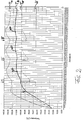
- Fig. 2 shows a test course in which a container is filled with a relatively small amount of food.
- Fig. 3 shows the curves for an experiment in which the container is almost full of food.
- the container is first heated with a constantly high heating output, whereupon the temperatures of the temperature sensors 6 and 8 rise sharply.
- the average temperature T M of the three peripheral temperature sensors 8, which is determined in the control device 12 as the average of the three individual temperatures of the temperature sensors 8, rises considerably more than the temperature of the average temperature sensor 6.
- the bottom of the container normally bulges out slightly, so that there is a gap in the central region between the bottom of the container and the glass ceramic, which considerably deteriorates the heat transfer.
- there may be the effect that the peripheral Area of the container is heated more than the middle area because of the transition there in the side walls.
- the temperature T 2 of the temperature sensor 6 initially remains below the temperature T W of the food, in the case of water.
- the time heating of the temperature sensor 6 no longer increases, but decreases, ie the curve T 2 shown has a first turning point WP; their first time derivative goes through a maximum and their second time derivative has a zero point.
- An evaluation circuit contained in the control device 12 (clocked reading of the temperatures and determination as to whether the difference between two temperature values read one after the other increases or decreases) determines the presence of the turning point WP of the curve T 2 and evaluates this as the start of cooking, whereupon the heating output H, for example, accordingly a cooking intensity set or selected on the operating and display unit 14 is withdrawn.
- Fig. 3 shows an experiment in the event that the container is largely filled with food (again water).
- the heating of the water then takes place considerably more slowly, the curve T 2 being essentially above the curve T W from the beginning.
- the curve T 2 does not pass an inflection point, so that this criterion cannot be used to determine the cooking point.
- the point in time P is used as the boiling point at which the temporal change in the temperature T 1 of the temperature sensor 8 with the highest temperature falls below a predetermined value which can advantageously be set according to the fermentation intensity. The same procedure can be used if you want to boil again after adding water (arrow V).
- the cooking point is either the point in time at which the temperature profile of the generally relatively coldest temperature sensor has a turning point or the point in time in the temperature profile at which the change over time advantageously falls below a preset threshold value, depending on the which criterion is met first.
- their mean value can also be used to display the cooking point if the three temperatures do not deviate too much from one another.
- the arrangement of the temperature sensors 2 and 8 according to FIG. 1 can be used for further statements. If, for example, the temperatures of the peripherally arranged temperature sensors 8 are different from one another, this indicates that the The container is asymmetrical on the hob 2 or has no planar container bottom and can be indicated acoustically and / or optically via a corresponding display of the operating and display unit 14. If the temperature of the middle temperature sensor 6 deviates by a predetermined amount from that of the outer temperature sensor 8, this can be taken as an indication of poor container quality and can also be displayed. Furthermore, depending on the temperature deviation, the continued cooking output can be adjusted to compensate for poor pot quality.
- the cooking point is determined by evaluating the temperature curve of the generally coldest temperature sensor for a turning point and the temperature curve of the generally hottest temperature sensor for falling below a predetermined threshold value due to its change over time, this is also asymmetrical on the hob 2 standing container a reasonably safe determination of their boiling point possible.
- peripheral temperature sensor 8 does not have to consist of glass ceramic, but can also consist of another material, preferably a material whose thermal conductivity and thermal capacity are comparatively small.
- a heating device 4 based on another heating principle can also be provided, for example one Radiant heating or resistance heating.
- the heating device can be formed with electrical resistance structures, which are arranged on the underside of a ceramic provided as a hob, for example a silicon nitride or a silicon carbide ceramic.
Landscapes
- Engineering & Computer Science (AREA)
- Chemical & Material Sciences (AREA)
- General Physics & Mathematics (AREA)
- Physics & Mathematics (AREA)
- General Health & Medical Sciences (AREA)
- Life Sciences & Earth Sciences (AREA)
- Analytical Chemistry (AREA)
- Biochemistry (AREA)
- Health & Medical Sciences (AREA)
- Food Science & Technology (AREA)
- Immunology (AREA)
- Pathology (AREA)
- Ceramic Engineering (AREA)
- Automation & Control Theory (AREA)
- Electric Stoves And Ranges (AREA)
- Cookers (AREA)
- Induction Heating Cooking Devices (AREA)
Applications Claiming Priority (4)
| Application Number | Priority Date | Filing Date | Title |
|---|---|---|---|
| DE19619141 | 1996-05-11 | ||
| DE19619141 | 1996-05-11 | ||
| DE19648397A DE19648397A1 (de) | 1996-05-11 | 1996-11-22 | Verfahren und Vorrichtung zum Erkennen des Kochpunktes von Kochgut |
| DE19648397 | 1996-11-22 |
Publications (2)
| Publication Number | Publication Date |
|---|---|
| EP0806887A1 true EP0806887A1 (fr) | 1997-11-12 |
| EP0806887B1 EP0806887B1 (fr) | 2004-05-19 |
Family
ID=26025637
Family Applications (1)
| Application Number | Title | Priority Date | Filing Date |
|---|---|---|---|
| EP97104241A Expired - Lifetime EP0806887B1 (fr) | 1996-05-11 | 1997-03-13 | Procédé et dispositif pour reconnaítre le stade de cuisson d'aliments à cuire |
Country Status (1)
| Country | Link |
|---|---|
| EP (1) | EP0806887B1 (fr) |
Cited By (10)
| Publication number | Priority date | Publication date | Assignee | Title |
|---|---|---|---|---|
| US6118105A (en) * | 1999-07-19 | 2000-09-12 | General Electric Company | Monitoring and control system for monitoring the boil state of contents of a cooking utensil |
| US6118104A (en) * | 1999-03-19 | 2000-09-12 | General Electric Company | Method and apparatus for boil state detection based on acoustic signal features |
| US6169486B1 (en) | 1999-07-19 | 2001-01-02 | General Electric Company | Monitoring and control system for monitoring the temperature of a glass ceramic cooktop |
| US6236025B1 (en) | 1999-03-19 | 2001-05-22 | General Electric Company | Acoustic sensing system for boil state detection and method for determining boil state |
| EP1028602A3 (fr) * | 1999-02-13 | 2002-01-02 | Schott Glas | Procédé de reconnaissance d'une cuisson à vide d'un élément de vaisselle placé sur des plaques possédant une surface de cuisson vitro-céramique ainsi que le dispositif correspondant |
| US6433693B1 (en) | 2000-07-31 | 2002-08-13 | General Electric Company | Apparatus and method for boil phase detection based on acoustic signal features |
| DE10329840A1 (de) * | 2003-06-27 | 2005-01-20 | E.G.O. Elektro-Gerätebau GmbH | Verfahren und Vorrichtung zur Erkennung von Erwärmungsvorgängen |
| WO2005076667A1 (fr) * | 2004-02-04 | 2005-08-18 | Ceramaspeed Limited | Dispositif de chauffage electrique |
| EP1420613A3 (fr) * | 2002-11-15 | 2006-03-22 | Electrolux Home Products Corporation N.V. | Procédé et dispositif de surveillance thermique d'un ustensile de cuisson chauffable inductivement |
| FR2965330A1 (fr) * | 2010-09-23 | 2012-03-30 | Jaeger | Capteur pour inducteur ameliore |
Citations (7)
| Publication number | Priority date | Publication date | Assignee | Title |
|---|---|---|---|---|
| DE3314398A1 (de) * | 1983-04-21 | 1984-10-25 | Kurt Wolf & Co Kg, 7547 Wildbad | Vorrichtung zur steuerung des gar- bzw. kochvorganges in einem kochgefaess |
| DE3323399A1 (de) * | 1983-06-29 | 1985-01-10 | Kurt Wolf & Co Kg, 7547 Wildbad | Verfahren und vorrichtung zum steuern des gar- bzw. kochvorganges bei einem dampfdruckkochgefaess |
| DE3447296C1 (de) * | 1984-12-24 | 1986-05-07 | Kurt Wolf & Co Kg, 7547 Wildbad | Vorrichtung zum Steuern des Gar- bzw. Kochvorganges in einem Dampfdruckkochgefaess |
| DE3642181C1 (de) * | 1986-12-10 | 1988-04-14 | Wolf & Co Kg Kurt | Anordnung zum Beeinflussen der Gar- bzw. Kochzeit bei einem Kochgefaess |
| DE3642180A1 (de) * | 1986-12-10 | 1988-06-23 | Wolf & Co Kg Kurt | Anordnung zum beeinflussen der gar- bzw. kochzeit bei einem kochgefaess |
| DE4007680A1 (de) * | 1990-03-10 | 1991-09-19 | Grass Ag | Heizplatte |
| DE4413979A1 (de) * | 1994-04-21 | 1995-10-26 | Bosch Siemens Hausgeraete | Sensorgesteuerte Garungseinheit |
Family Cites Families (2)
| Publication number | Priority date | Publication date | Assignee | Title |
|---|---|---|---|---|
| DE4136133A1 (de) * | 1991-11-02 | 1993-05-06 | Philips Patentverwaltung Gmbh, 2000 Hamburg, De | Anordnung zur regelung der heizleistung fuer einen kochtopf |
| DE4336752C2 (de) * | 1993-10-28 | 1999-06-24 | Aeg Hausgeraete Gmbh | Verfahren zum Zubereiten von Speisen in einem Kochgeschirr auf einem Kochfeld aus Keramik, insbesondere Glaskeramik |
-
1997
- 1997-03-13 EP EP97104241A patent/EP0806887B1/fr not_active Expired - Lifetime
Patent Citations (7)
| Publication number | Priority date | Publication date | Assignee | Title |
|---|---|---|---|---|
| DE3314398A1 (de) * | 1983-04-21 | 1984-10-25 | Kurt Wolf & Co Kg, 7547 Wildbad | Vorrichtung zur steuerung des gar- bzw. kochvorganges in einem kochgefaess |
| DE3323399A1 (de) * | 1983-06-29 | 1985-01-10 | Kurt Wolf & Co Kg, 7547 Wildbad | Verfahren und vorrichtung zum steuern des gar- bzw. kochvorganges bei einem dampfdruckkochgefaess |
| DE3447296C1 (de) * | 1984-12-24 | 1986-05-07 | Kurt Wolf & Co Kg, 7547 Wildbad | Vorrichtung zum Steuern des Gar- bzw. Kochvorganges in einem Dampfdruckkochgefaess |
| DE3642181C1 (de) * | 1986-12-10 | 1988-04-14 | Wolf & Co Kg Kurt | Anordnung zum Beeinflussen der Gar- bzw. Kochzeit bei einem Kochgefaess |
| DE3642180A1 (de) * | 1986-12-10 | 1988-06-23 | Wolf & Co Kg Kurt | Anordnung zum beeinflussen der gar- bzw. kochzeit bei einem kochgefaess |
| DE4007680A1 (de) * | 1990-03-10 | 1991-09-19 | Grass Ag | Heizplatte |
| DE4413979A1 (de) * | 1994-04-21 | 1995-10-26 | Bosch Siemens Hausgeraete | Sensorgesteuerte Garungseinheit |
Cited By (14)
| Publication number | Priority date | Publication date | Assignee | Title |
|---|---|---|---|---|
| EP1028602A3 (fr) * | 1999-02-13 | 2002-01-02 | Schott Glas | Procédé de reconnaissance d'une cuisson à vide d'un élément de vaisselle placé sur des plaques possédant une surface de cuisson vitro-céramique ainsi que le dispositif correspondant |
| US6118104A (en) * | 1999-03-19 | 2000-09-12 | General Electric Company | Method and apparatus for boil state detection based on acoustic signal features |
| US6236025B1 (en) | 1999-03-19 | 2001-05-22 | General Electric Company | Acoustic sensing system for boil state detection and method for determining boil state |
| US6118105A (en) * | 1999-07-19 | 2000-09-12 | General Electric Company | Monitoring and control system for monitoring the boil state of contents of a cooking utensil |
| US6169486B1 (en) | 1999-07-19 | 2001-01-02 | General Electric Company | Monitoring and control system for monitoring the temperature of a glass ceramic cooktop |
| US6433693B1 (en) | 2000-07-31 | 2002-08-13 | General Electric Company | Apparatus and method for boil phase detection based on acoustic signal features |
| EP1420613A3 (fr) * | 2002-11-15 | 2006-03-22 | Electrolux Home Products Corporation N.V. | Procédé et dispositif de surveillance thermique d'un ustensile de cuisson chauffable inductivement |
| EP2271175A3 (fr) * | 2002-11-15 | 2011-01-19 | Electrolux Home Products Corporation N.V. | Procédé et dispositif de surveillance thermique d'un ustensile de cuisson chauffable inductivement |
| US6888110B2 (en) | 2003-06-27 | 2005-05-03 | E.G.O. Elektro-Geraetebau Gmbh | Method and device for detecting heating processes |
| DE10329840A1 (de) * | 2003-06-27 | 2005-01-20 | E.G.O. Elektro-Gerätebau GmbH | Verfahren und Vorrichtung zur Erkennung von Erwärmungsvorgängen |
| WO2005076667A1 (fr) * | 2004-02-04 | 2005-08-18 | Ceramaspeed Limited | Dispositif de chauffage electrique |
| US7652229B2 (en) | 2004-02-04 | 2010-01-26 | Stylewell Limited | Electrical heating arrangement |
| KR101155212B1 (ko) * | 2004-02-04 | 2012-06-14 | 스타일웰 리미티드 | 전열기 |
| FR2965330A1 (fr) * | 2010-09-23 | 2012-03-30 | Jaeger | Capteur pour inducteur ameliore |
Also Published As
| Publication number | Publication date |
|---|---|
| EP0806887B1 (fr) | 2004-05-19 |
Similar Documents
| Publication | Publication Date | Title |
|---|---|---|
| DE19648397A1 (de) | Verfahren und Vorrichtung zum Erkennen des Kochpunktes von Kochgut | |
| DE4022846C2 (de) | Vorrichtung zur Leistungssteuerung und -begrenzung bei einer Heizfläche aus Glaskeramik oder einem vergleichbaren Material | |
| EP2211591B1 (fr) | Procédé de fonctionnement d'un champ de cuisson doté d'une multitude d'éléments de chauffage | |
| EP1625774B1 (fr) | Regulation de temperature destinee a un element de chauffage chauffe par induction | |
| EP2271175B1 (fr) | Procédé et dispositif de surveillance thermique d'un ustensile de cuisson chauffable inductivement | |
| EP3111723B1 (fr) | Table de cuisson comprenant une multitude d'éléments chauffants | |
| DE69026553T2 (de) | Temperaturmessvorrichtung für Induktionskochgerät und Gerät mit einer solchen Vorrichtung | |
| DE69015364T2 (de) | Regelvorrichtung und -verfahren für kochgerät. | |
| EP0467134A2 (fr) | Procédé et appareil pour indiquer un état de charge anormal thermique d'un panneau chauffé | |
| EP3267113B1 (fr) | Procédé de fonctionnement d'une plaque de cuisson | |
| EP0652688B1 (fr) | Méthode pour commander la puissance de chauffage d'une plaque vitro-céramique selon les conditions de cuisson requises | |
| EP0806887B1 (fr) | Procédé et dispositif pour reconnaítre le stade de cuisson d'aliments à cuire | |
| EP2460388A1 (fr) | Table de cuisson avec au moins deux zones de cuisson | |
| EP3013120B2 (fr) | Plaque de cuisson | |
| EP1391141B1 (fr) | Procede et dispositif pour limiter et/ou reguler la temperature superficielle d'une plaque de cuisson | |
| DE4413979C2 (de) | Sensorgesteuerte Garungseinheit und Gargerät | |
| EP3513698B1 (fr) | Procédé de fonctionnement d'un élément chauffant | |
| EP1732357A2 (fr) | Dispositif de chauffage pour appareils de cuisson à induction | |
| EP3136822B1 (fr) | Procede de determination de temperature | |
| WO2010081637A1 (fr) | Table de cuisson avec plaque de couverture | |
| DE102007012379A1 (de) | Kochfeldvorrichtung | |
| DE102004059822A1 (de) | Sensorvorrichtung für ein Kochfeld, Verfahren zum Betrieb einer Sensorvorrichtung und Verwendung eines Temperatursensors als Topferkennungssensor | |
| DE102004016631A1 (de) | Vorrichtung und Verfahren zur Überwachung der Temperatur eines Kochgeschirrs auf einer Abdeckung eines Kochfeldes sowie von weiteren Vorgängen auf der Abdeckung | |
| DE102017114951A1 (de) | Verfahren zum Betrieb einer Kochstelle eines Induktionskochfelds mit einem Kochgeschirr | |
| DE102010016110B4 (de) | Verfahren zur Regelung der Leistungszufuhr für eine Induktions-Kochstelle und Vorrichtung zur Durchführung des Verfahrens |
Legal Events
| Date | Code | Title | Description |
|---|---|---|---|
| PUAI | Public reference made under article 153(3) epc to a published international application that has entered the european phase |
Free format text: ORIGINAL CODE: 0009012 |
|
| 17P | Request for examination filed |
Effective date: 19970718 |
|
| AK | Designated contracting states |
Kind code of ref document: A1 Designated state(s): CH DE FR IT LI |
|
| GRAP | Despatch of communication of intention to grant a patent |
Free format text: ORIGINAL CODE: EPIDOSNIGR1 |
|
| GRAS | Grant fee paid |
Free format text: ORIGINAL CODE: EPIDOSNIGR3 |
|
| GRAA | (expected) grant |
Free format text: ORIGINAL CODE: 0009210 |
|
| AK | Designated contracting states |
Kind code of ref document: B1 Designated state(s): CH DE FR IT LI |
|
| REG | Reference to a national code |
Ref country code: CH Ref legal event code: NV Representative=s name: TROESCH SCHEIDEGGER WERNER AG Ref country code: CH Ref legal event code: EP |
|
| REF | Corresponds to: |
Ref document number: 59711629 Country of ref document: DE Date of ref document: 20040624 Kind code of ref document: P |
|
| ET | Fr: translation filed | ||
| PLBE | No opposition filed within time limit |
Free format text: ORIGINAL CODE: 0009261 |
|
| STAA | Information on the status of an ep patent application or granted ep patent |
Free format text: STATUS: NO OPPOSITION FILED WITHIN TIME LIMIT |
|
| 26N | No opposition filed |
Effective date: 20050222 |
|
| PGFP | Annual fee paid to national office [announced via postgrant information from national office to epo] |
Ref country code: IT Payment date: 20070618 Year of fee payment: 11 |
|
| PGFP | Annual fee paid to national office [announced via postgrant information from national office to epo] |
Ref country code: CH Payment date: 20090326 Year of fee payment: 13 |
|
| PG25 | Lapsed in a contracting state [announced via postgrant information from national office to epo] |
Ref country code: IT Free format text: LAPSE BECAUSE OF NON-PAYMENT OF DUE FEES Effective date: 20080313 |
|
| REG | Reference to a national code |
Ref country code: CH Ref legal event code: PL |
|
| PG25 | Lapsed in a contracting state [announced via postgrant information from national office to epo] |
Ref country code: LI Free format text: LAPSE BECAUSE OF NON-PAYMENT OF DUE FEES Effective date: 20100331 Ref country code: CH Free format text: LAPSE BECAUSE OF NON-PAYMENT OF DUE FEES Effective date: 20100331 |
|
| REG | Reference to a national code |
Ref country code: FR Ref legal event code: PLFP Year of fee payment: 19 |
|
| PGFP | Annual fee paid to national office [announced via postgrant information from national office to epo] |
Ref country code: DE Payment date: 20150320 Year of fee payment: 19 |
|
| PGFP | Annual fee paid to national office [announced via postgrant information from national office to epo] |
Ref country code: FR Payment date: 20150319 Year of fee payment: 19 |
|
| REG | Reference to a national code |
Ref country code: DE Ref legal event code: R119 Ref document number: 59711629 Country of ref document: DE |
|
| REG | Reference to a national code |
Ref country code: FR Ref legal event code: ST Effective date: 20161130 |
|
| PG25 | Lapsed in a contracting state [announced via postgrant information from national office to epo] |
Ref country code: FR Free format text: LAPSE BECAUSE OF NON-PAYMENT OF DUE FEES Effective date: 20160331 Ref country code: DE Free format text: LAPSE BECAUSE OF NON-PAYMENT OF DUE FEES Effective date: 20161001 |