EP0807393A2 - Vorrichtung zum Öffnen und Schliessen eines Vorhanges des Linearmotortyps - Google Patents
Vorrichtung zum Öffnen und Schliessen eines Vorhanges des Linearmotortyps Download PDFInfo
- Publication number
- EP0807393A2 EP0807393A2 EP97107884A EP97107884A EP0807393A2 EP 0807393 A2 EP0807393 A2 EP 0807393A2 EP 97107884 A EP97107884 A EP 97107884A EP 97107884 A EP97107884 A EP 97107884A EP 0807393 A2 EP0807393 A2 EP 0807393A2
- Authority
- EP
- European Patent Office
- Prior art keywords
- linear motor
- ring
- movable element
- outer rail
- curtain
- Prior art date
- Legal status (The legal status is an assumption and is not a legal conclusion. Google has not performed a legal analysis and makes no representation as to the accuracy of the status listed.)
- Withdrawn
Links
Images




Classifications
-
- A—HUMAN NECESSITIES
- A47—FURNITURE; DOMESTIC ARTICLES OR APPLIANCES; COFFEE MILLS; SPICE MILLS; SUCTION CLEANERS IN GENERAL
- A47H—FURNISHINGS FOR WINDOWS OR DOORS
- A47H5/00—Devices for drawing draperies, curtains, or the like
- A47H5/02—Devices for opening and closing curtains
- A47H5/032—Devices with guiding means and draw cords
- A47H5/0325—Devices with guiding means and draw cords using electrical or electronical drive, detecting or controlling means
-
- A—HUMAN NECESSITIES
- A47—FURNITURE; DOMESTIC ARTICLES OR APPLIANCES; COFFEE MILLS; SPICE MILLS; SUCTION CLEANERS IN GENERAL
- A47H—FURNISHINGS FOR WINDOWS OR DOORS
- A47H5/00—Devices for drawing draperies, curtains, or the like
- A47H5/02—Devices for opening and closing curtains
-
- A—HUMAN NECESSITIES
- A47—FURNITURE; DOMESTIC ARTICLES OR APPLIANCES; COFFEE MILLS; SPICE MILLS; SUCTION CLEANERS IN GENERAL
- A47H—FURNISHINGS FOR WINDOWS OR DOORS
- A47H2201/00—Means for connecting curtains
- A47H2201/01—Magnets
Definitions
- the present invention relates to a linear motor type curtain opening and closing device, particularly to a linear motor type curtain opening and closing device of a ring runner type.
- a linear motor is currently used at a curtain rail to electrically open and close a curtain in residence, an office building, a hotel and the like. An explanation will be given of the structure of a linear motor in reference to Fig. 6.
- Fig. 6 is a perspective view showing constituent parts of a linear motor.
- the linear motor is constituted by stators 40A and 40B incorporated in an outer rail 220, a movable element 50 incorporated in the outer rail 220 abrasively in the longitudinal direction, a strip-like cable 30 accommodated at an upper wall of the outer rail 220.
- the section of the outer rail 220 is formed substantially in an inversed-U shape.
- the stators 40A and 40B each comprising a permanent magnet 42 and a yoke 44 along the longitudinal direction are incorporated in the outer rail 220.
- the movable element 50 is provided with three armatures 52A, 52B and 52C in a substantially cylindrical shape and is abrasively mounted in the outer rail 220.
- a forefront runner 74 is connected to the lower end of the movable element 50 via a metal piece, not illustrated.
- the lower end of the forefront runner 74 is projected downwardly from an opening 220h of the outer rail 220.
- Wheels 74a attached to the forefront runner 74 are constituted to roll over horizontal pieces 220g formed at the lower end of the outer rail 220.
- Runners 76 for hanging a curtain, not illustrated, are arranged at the inside of the outer rail 220 along with the forefront runner 74.
- the rail (outer rail 220) is uncovered and curtain hook hanging portions of the runners 74 and 76 are exposed from the opening 220h at the lower side of the rail.
- the outer rail 220 is not seen by attaching the upper end of the curtain, not illustrated, at a position higher than the upper end of the outer rail 220.
- ring-like runners referred to as ring runners are arranged to the outer periphery of a rail in a manual type curtain rail and the ring runners are positively shown along with the curtain rail whereby an accent is constituted in view of design.
- a ring runner 80 connected to the movable element 50 is inclined at the start of running and is twisted in respect of the outer rail 220 whereby the ring runner 80 cannot be driven smoothly.
- the linear motor of the present invention is achieved in order to solve the above-described problem and it is an object of the present invention to provide a linear motor type curtain opening and closing device capable of smoothly running ring runners.
- a linear motor type curtain opening and closing device of the present invention comprises:
- the forefront ring-like runners is fixed to the movable element and accordingly, in running the movable element, the forefront ring-like runner moving along with the movable element is not inclined and is not twisted in respect of the rail main body.
- Fig. 1(A) is a sectional view of a linear motor according to a first embodiment and Fig. 1(B) is a side view of the linear motor.
- Fig. 2 is a perspective view of constituent parts of the linear motor shown by Fig. 1.
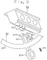
- Fig. 3 is a perspective view showing attachment of a ring runner to a movable element.
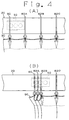
- Figs. 4(A) and 4(B) are side views showing opening and closing operation of a curtain by a linear motor according to the first embodiment where Fig. 4(A) shows a state before opening and closing a curtain and Fig. 4(B) shows a state of opening and closing the curtain.
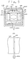
- Fig. 5(A) is a sectional view of a linear motor according to a second embodiment and Fig. 5 (B) is a side view of the linear motor.
- Fig. 6 is a perspective view of constituent parts of a linear motor according to a conventional technology.
- Fig. 7 is a side view showing opening and closing operation of a curtain by the linear motor of the conventional technology.
- Fig. 1(A) is a sectional view of a linear motor 10 constituting a linear motor type curtain opening and closing device according to a first embodiment and Fig. 1(B) is a side view thereof. Further, Fig. 2 is a perspective view showing constituent parts of the linear motor 10. According to the linear motor 10, a ring runner 80 is fixed to a movable element 50 running in the linear motor 10.
- the linear motor is constituted by stators 40A and 40B incorporated in an outer rail 20 and the movable element 50 incorporated in the outer rail 20 abrasively in the longitudinal direction.
- the outer rail 20 is formed in a cylindrical shape and a pair of magnet fitting grooves 20e each having a section in a channel-like shape are provided at intermediate portions in the up and down direction of the outer rail 20.
- the stators 40A and 40B each comprising a permanent magnet 42 and a yoke 44 are incorporated in the respective magnet fitting grooves 20e in the longitudinal direction.
- the permanent magnet 42 on the side of the stator 40A is formed with a plurality of magnetized portions 42A, 42B, 42C,... (refer to Fig. 2) in the longitudinal direction and the respective magnetized portions 42A, 42B, 42C,... are magnetized in the thickness direction of the permanent magnet 42.
- magnetizing polarities of the respective magnetized portions which are mutually contiguous to each other in the respective magnetized portions 42A, 42B, 42C,..., are mutually reversed.
- the permanent magnet 42 on the side of the stator 40B is similarly magnetized in the thickness direction and magnetizing polarities of contiguous respective magnetized portions are mutually reversed. Also, respective two opposed magnetic poles of the magnetized portions of the permanent magnets 42 on the side of the stator 40A and on the side of the stator 40B which are opposed to each other, are provided with reverse polarities.
- a cable fitting groove 20C for incorporating a strip-like cable 30 is formed at the upper portion of the outer rail 20 as illustrated by Fig. 1(A).
- the cable 30 is provided with a flexible insulating film and two electrode patterns 30A and 30B are formed in a pattern shape interposing a narrow gap 30C in a broken line along the longitudinal direction as shown by Fig. 2.
- the electrode patterns 30A and 30B each is formed by a copper foil of the illustrated shape and is constituted to repeat at a predetermined pitch to correspond to the couple of permanent magnets 42.
- a movable element 50 is provided with a head wall 56 having an elongated plate shape and the head wall 56 is mounted abrasively on respective upper walls 20j of the two left and right magnet fitting grooves 20e in the longitudinal direction as shown by Fig.1(A).
- the movable element 50 is provided with a body 58 having a rectangular parallelepiped shape and the body 58 is hung from the central portion in the left and right direction of the head wall 56 and between respective two opposed ends of the two left and right magnet fitting grooves 20e movably in the longitudinal direction (refer to Fig. 1(A)).
- the body 58 is provided with three armatures 52A, 52B and 52C each having a substantially cylindrical shape. As shown by Fig.
- each of the armatures 52A, 52B and 52C is provided with a core 59 made of iron and the axial direction of the core 59 is in parallel to the magnetizing direction of the respective magnetized portions of the permanent magnets 42 of the stators 40A and 40B (that is, orthogonal to the longitudinal direction of the two permanent magnets 42).
- a coil 57 is wound around the outer periphery of the core 59 and pole magnetisms of the both ends of the core 59 are determined in accordance with the polarity of a direct current voltage applied on brushes 54 connected to the coil 57.
- the pair of brushes 54 are respectively projected from portions of the upper face of the head wall 56 corresponding to the respective armatures 52A, 52B and 52C and front ends thereof are brought into contact with either of the two electrode patterns 30A and 30B of the cable 30 as shown by Fig. 2.
- Fig. 3 is a view magnifying a lower end portion of a ring runner 80.
- a ring runner 80 is integrally formed by a synthetic resin and is constituted by an attaching portion 80B horizontally extended to be able to fix to the movable element 50, a ring portion 80C surrounding the outer periphery of the outer rail 20 as shown by Fig. 1(A), a connecting portion 80D for connecting the attaching portion 80B and the ring portion 80C, and a hanging portion 80A for hanging a curtain arranged at the lower end of the ring portion 80C.
- the connecting portion 80D is extended downwardly from an opening groove 20h formed at the lower end of the outer rail 20 to support the ring portion 80C as shown by Fig. 1(A).
- screw holes 50a, 50b and 50c are perforated at the lower end of the movable element 50.
- screw holes 80a, not illustrated, 80b and 80c are perforated also at the attaching portion 80B of the ring runner 80.
- the ring runner 80 is fixed to the movable element 50 by fastening screws 84 to the screw holes 50a, 50b and 50c and the screw holes 80a, 80b and 80c.
- FIG. 4 (A) and Fig. 4(B) An explanation will be given of opening and closing operation of a curtain by the linear motor of the first embodiment in reference to Fig. 4 (A) and Fig. 4(B).
- the forefront ring runner 80 at the left end in Fig. 4(A) is fixed to the movable element 50 as explained above in reference to Figs. 1(A), 1(B), 2 and 3 and other ring runners 82A, 82B and 82C are fitted abrasively to the outer rail 20.
- a curtain 90 hangs down from the ring runners 80, 82A, 82B and 82C via curtain hooks.
- the ring runner 80 is fixed to the movable element and therefore, the ring runner 80 is not inclined and is not twisted in respect of the outer rail. Therefore, the curtain 90 can be opened and closed by abrasively moving the ring runner 80 smoothly on the outer rail 20.
- Fig. 5(A) shows a sectional view of a linear motor 110 constituting a linear motor type curtain opening and closing device according to the second embodiment and Fig. 5(B) shows a side view thereof.
- the outer rail 20 is formed in a cylindrical shape
- an outer rail 120 is formed in a shape of a square prism.
- the same reference notations are used in respect of members similar to those in the first embodiment and an explanation thereof will be omitted.
- a ring runner 180 is integrally formed by a synthetic resin and is constituted by an attaching portion 180B horizontally extended to be able to fix to the movable element 50, a rectangular ring portion 180C surrounding the outer periphery of the outer rail 20, a connecting portion 180D for connecting the attaching portion 180B and the ring portion 180C and a hanging portion 180A for hanging a curtain arranged at the lower end of the ring portion 180C.
- the connecting portion 180D is extended downwardly from an opening groove 120h formed at the lower end of the outer rail 120 to support the ring portion 180C. Similar to the first embodiment explained above in reference to Fig. 3, the ring runner 180 is fixed to the movable element 50 by fastening screws to screw holes, not illustrated, of the movable element 50 and screw holes, not illustrated, formed at the attaching portion 180B of the ring runner 180.
- the ring runner 180 is fixed to the movable element 50 and therefore, the ring runner 180 is not inclined and is not twisted in respect of the outer rail 120 in opening and closing the curtain. Therefore, the ring runner 180 is abrasively moved smoothly on the outer rail 120 whereby a curtain can be opened and closed.
- the present invention is naturally applicable to a linear motor of a coil movable type.
- the ring runner is fixed to the movable element and therefore, the ring runner is not twisted in respect of the outer rail 20 whereby the curtain can be opened and closed smoothly.
Landscapes
- Linear Motors (AREA)
- Curtains And Furnishings For Windows Or Doors (AREA)
Applications Claiming Priority (2)
| Application Number | Priority Date | Filing Date | Title |
|---|---|---|---|
| JP14797696A JP3180670B2 (ja) | 1996-05-17 | 1996-05-17 | リニアモータ式カーテン開閉装置 |
| JP147976/96 | 1996-05-17 |
Publications (2)
| Publication Number | Publication Date |
|---|---|
| EP0807393A2 true EP0807393A2 (de) | 1997-11-19 |
| EP0807393A3 EP0807393A3 (de) | 1998-04-01 |
Family
ID=15442362
Family Applications (1)
| Application Number | Title | Priority Date | Filing Date |
|---|---|---|---|
| EP97107884A Withdrawn EP0807393A3 (de) | 1996-05-17 | 1997-05-14 | Vorrichtung zum Öffnen und Schliessen eines Vorhanges des Linearmotortyps |
Country Status (2)
| Country | Link |
|---|---|
| EP (1) | EP0807393A3 (de) |
| JP (1) | JP3180670B2 (de) |
Cited By (3)
| Publication number | Priority date | Publication date | Assignee | Title |
|---|---|---|---|---|
| GB2342031A (en) * | 1998-09-29 | 2000-04-05 | Wu King Sheng | Magnetically driven curtain |
| RU2478252C2 (ru) * | 2011-06-28 | 2013-03-27 | Государственное образовательное учреждение высшего профессионального образования "Курганский государственный университет" | Линейная электрическая машина |
| CN121984302A (zh) * | 2026-04-07 | 2026-05-05 | 深圳市唯卓仕科技有限公司 | 音圈电机、音圈电机的控制方法及摄影镜头 |
Families Citing this family (1)
| Publication number | Priority date | Publication date | Assignee | Title |
|---|---|---|---|---|
| JP5226483B2 (ja) * | 2008-11-28 | 2013-07-03 | カヤバ工業株式会社 | リニアアクチュエータ |
Family Cites Families (6)
| Publication number | Priority date | Publication date | Assignee | Title |
|---|---|---|---|---|
| FR978092A (fr) * | 1948-11-16 | 1951-04-09 | Système de tirage pour rideaux de forme arrondie | |
| GB1498927A (en) * | 1976-05-27 | 1978-01-25 | Fisher H | Curtain suspension device |
| FR2379231A7 (fr) * | 1977-01-26 | 1978-08-25 | Gonon Jean | Perfectionnement aux tringles a rideaux |
| DE2738251A1 (de) * | 1977-08-25 | 1979-03-01 | Maerklin & Cie Gmbh Geb | Vorrichtung zum oeffnen oder schliessen eines vorhanges vor einem fenster eines hauses |
| JPH0246157A (ja) * | 1988-05-25 | 1990-02-15 | Fuji Electric Co Ltd | 横行移動体のリニアパルスモータ式駆動装置 |
| JPH06245479A (ja) * | 1993-02-18 | 1994-09-02 | Shinsei Kogyo Kk | 筒型誘導リニアモータ |
-
1996
- 1996-05-17 JP JP14797696A patent/JP3180670B2/ja not_active Expired - Fee Related
-
1997
- 1997-05-14 EP EP97107884A patent/EP0807393A3/de not_active Withdrawn
Cited By (3)
| Publication number | Priority date | Publication date | Assignee | Title |
|---|---|---|---|---|
| GB2342031A (en) * | 1998-09-29 | 2000-04-05 | Wu King Sheng | Magnetically driven curtain |
| RU2478252C2 (ru) * | 2011-06-28 | 2013-03-27 | Государственное образовательное учреждение высшего профессионального образования "Курганский государственный университет" | Линейная электрическая машина |
| CN121984302A (zh) * | 2026-04-07 | 2026-05-05 | 深圳市唯卓仕科技有限公司 | 音圈电机、音圈电机的控制方法及摄影镜头 |
Also Published As
| Publication number | Publication date |
|---|---|
| JPH09299226A (ja) | 1997-11-25 |
| JP3180670B2 (ja) | 2001-06-25 |
| EP0807393A3 (de) | 1998-04-01 |
Similar Documents
| Publication | Publication Date | Title |
|---|---|---|
| JP2789335B2 (ja) | カーテン駆動装置 | |
| JPS6327946B2 (de) | ||
| JP3180670B2 (ja) | リニアモータ式カーテン開閉装置 | |
| JP3113412B2 (ja) | リニアモータ及びそれを用いたカーテンレール | |
| RU2040102C1 (ru) | Линейный асинхронный двигатель | |
| JP2023140403A (ja) | 筒型リニアモータ | |
| KR100978828B1 (ko) | 분할 코일체를 갖는 회전판과 분할 자석체를 갖는 고정판에의한 전동장치 | |
| JP3528686B2 (ja) | リニアモータ | |
| JPH0870566A (ja) | リニアモータの連結部構造 | |
| JP2508614B2 (ja) | リニアモ―タ | |
| JP3139407B2 (ja) | 電動カーテンの端部構造 | |
| FR2315190A1 (fr) | Moteur electrique perfectionne | |
| JP2868381B2 (ja) | 電動カーテン装置 | |
| SU1411843A1 (ru) | Электромагнитный аппарат | |
| JP2522451B2 (ja) | リニアモ―タ | |
| JP2001095224A5 (de) | ||
| JPH10262806A (ja) | カーテンレール | |
| JP2641324B2 (ja) | リニアモータの切断方法 | |
| SU1042138A1 (ru) | Линейный шаговый электродвигатель | |
| SU1137555A1 (ru) | Однофазный синхронный электродвигатель | |
| SU1265936A1 (ru) | Линейный электродвигатель посто нного тока | |
| JPH1052027A (ja) | ブラシレス直流リニアモータ | |
| JP2914007B2 (ja) | リニアモータ | |
| JP3245952B2 (ja) | リニアモータ | |
| PL232583B1 (pl) | Silnik liniowy |
Legal Events
| Date | Code | Title | Description |
|---|---|---|---|
| PUAI | Public reference made under article 153(3) epc to a published international application that has entered the european phase |
Free format text: ORIGINAL CODE: 0009012 |
|
| AK | Designated contracting states |
Kind code of ref document: A2 Designated state(s): DE FR GB |
|
| PUAL | Search report despatched |
Free format text: ORIGINAL CODE: 0009013 |
|
| AK | Designated contracting states |
Kind code of ref document: A3 Designated state(s): DE FR GB |
|
| 17P | Request for examination filed |
Effective date: 19980610 |
|
| 17Q | First examination report despatched |
Effective date: 19990831 |
|
| STAA | Information on the status of an ep patent application or granted ep patent |
Free format text: STATUS: THE APPLICATION IS DEEMED TO BE WITHDRAWN |
|
| 18D | Application deemed to be withdrawn |
Effective date: 20001005 |