EP0807724B1 - Dispositif de sécurité pour ouvertures de lucarne - Google Patents
Dispositif de sécurité pour ouvertures de lucarne Download PDFInfo
- Publication number
- EP0807724B1 EP0807724B1 EP96107672A EP96107672A EP0807724B1 EP 0807724 B1 EP0807724 B1 EP 0807724B1 EP 96107672 A EP96107672 A EP 96107672A EP 96107672 A EP96107672 A EP 96107672A EP 0807724 B1 EP0807724 B1 EP 0807724B1
- Authority
- EP
- European Patent Office
- Prior art keywords
- profiles
- tubes
- rods
- security device
- profile
- Prior art date
- Legal status (The legal status is an assumption and is not a legal conclusion. Google has not performed a legal analysis and makes no representation as to the accuracy of the status listed.)
- Expired - Lifetime
Links
- 238000000034 method Methods 0.000 claims description 3
- 229910000831 Steel Inorganic materials 0.000 abstract description 8
- 239000010959 steel Substances 0.000 abstract description 8
- 239000004744 fabric Substances 0.000 abstract 1
- 238000009434 installation Methods 0.000 description 6
- 239000000463 material Substances 0.000 description 5
- 238000009826 distribution Methods 0.000 description 4
- 230000000694 effects Effects 0.000 description 4
- 210000002414 leg Anatomy 0.000 description 4
- 238000004519 manufacturing process Methods 0.000 description 4
- 238000010276 construction Methods 0.000 description 3
- 238000005452 bending Methods 0.000 description 2
- 230000035515 penetration Effects 0.000 description 2
- 238000005096 rolling process Methods 0.000 description 2
- 238000004026 adhesive bonding Methods 0.000 description 1
- 230000002411 adverse Effects 0.000 description 1
- 230000000903 blocking effect Effects 0.000 description 1
- 238000005520 cutting process Methods 0.000 description 1
- 230000006378 damage Effects 0.000 description 1
- 230000006735 deficit Effects 0.000 description 1
- 238000005516 engineering process Methods 0.000 description 1
- 238000005304 joining Methods 0.000 description 1
- 239000002184 metal Substances 0.000 description 1
- 238000007789 sealing Methods 0.000 description 1
- 210000000689 upper leg Anatomy 0.000 description 1
- 230000000007 visual effect Effects 0.000 description 1
- 238000003466 welding Methods 0.000 description 1
Images
Classifications
-
- E—FIXED CONSTRUCTIONS
- E04—BUILDING
- E04D—ROOF COVERINGS; SKY-LIGHTS; GUTTERS; ROOF-WORKING TOOLS
- E04D13/00—Special arrangements or devices in connection with roof coverings; Protection against birds; Roof drainage ; Sky-lights
- E04D13/03—Sky-lights; Domes; Ventilating sky-lights
- E04D13/0335—Skylight guards, security devices protecting skylights or preventing objects or persons from falling through skylight openings
-
- E—FIXED CONSTRUCTIONS
- E06—DOORS, WINDOWS, SHUTTERS, OR ROLLER BLINDS IN GENERAL; LADDERS
- E06B—FIXED OR MOVABLE CLOSURES FOR OPENINGS IN BUILDINGS, VEHICLES, FENCES OR LIKE ENCLOSURES IN GENERAL, e.g. DOORS, WINDOWS, BLINDS, GATES
- E06B9/00—Screening or protective devices for wall or similar openings, with or without operating or securing mechanisms; Closures of similar construction
- E06B9/01—Grilles fixed to walls, doors, or windows; Grilles moving with doors or windows; Walls formed as grilles, e.g. claustra
Definitions
- the invention relates to a safety device for a Roof opening, which according to the genus by the generic term of claim 1 is described.
- Roof openings must be secured against falling through. Such safety devices prescribed by standards on the one hand to the fall of objects To prevent roof breaks and fall injuries from on the Avoid people working on the roof. On the other hand, should be open Roof openings are closed in such a way that burglar resistance is guaranteed.
- German utility models G 91 05 567 and G 91 10 266 are kits for safety devices for roof openings known in which the opening cross-section of the roof opening secured against falling through with a plank frame and a grid becomes.
- the plank frame is under an upstand arranged and laid from the outside around the roof opening.
- a disadvantage of these so-called "under-construction solutions” for securing a roof opening is, however, the first caused by the additional installation of the plank frame constructional enlargement. This can also give the visual impression Suffer.
- a safety device is from the German utility model G 91 02 620 known, in which in a separate Fasteners are provided on the inside of the roof frame to which a fall protection can be attached.
- This type of securing roof openings also brings Disadvantage of tightness problems compared to the rest of the roof skin with yourself.
- this type of security device offers only a very limited protection against burglary since the Blocking of the roof opening from the outside relatively is easy to disassemble.
- the features of the preamble of claim 1 shows.
- the bars are placed between two base profiles using two cover profiles attached.
- the base profiles have a U-shape with one facing inwards Grid on both legs.
- the cover profiles also have a U-shape, but with an outward-facing grid on the legs.
- the cover profiles are in the Base profiles hammered in to engage.
- German utility model 92 10 122 U1 Another disadvantage of the grating device shown in German utility model 92 10 122 U1 is their very low adaptability to different Angular positions of the boundary walls of the roof opening.
- the inside or outside profiling of the different profile parts causes a rigid locking, due to the rigidity of the material (hammering in) hardly any room for installation Breakthrough limits that are not parallel to each other.
- the configuration according to the invention has an advantageous effect in that the hooking and locking process when attaching the cover profiles to the support profiles easily can be done in very different angular positions.
- the scope of the Roof penetration protection according to the invention is therefore not on such roof openings limited with parallel walls as parallel as possible.
- the support profiles are the safety device according to the invention flat longitudinal profiles, while the cover profiles are essentially of the same length are. Both profiles show both in the upper and in lower hooks and latching devices on.
- the design of the upper hanging device as a longitudinal groove and hook bar creates a weight pressure distribution on the whole Profile length. So that even at relatively low Dimensions and material thicknesses of the profiles are relatively large loads be included.
- the mechanical fastenings are completely covered by the cover strip after snapping into place.
- the Burglar resistance is given because the mechanical fastenings, for example from screws, rivets or all similar fasteners may not exist are more accessible from the outside. If special tightness requirements are of course also possible the support bar without damaging the roof opening add, e.g. by gluing or similar acting Joining measures.
- the safety bars or tubes or the ends of the steel mesh mat must be behind their mounting holes in the cover profile secured against being pulled out.
- securing means preferably clamping rings, Nuts, notched rivets or grooved pins and especially at the steel mesh mat by bending the rod ends and the Use of anti-slip devices.
- the rods or tubes can already be factory-made with the aforementioned securing devices be attached to the cover profile. After locking the cover profile the securing means are located with the rods on the support profile in the interior between the profiles and are from no longer accessible outside. In this regard, too Burglar security guaranteed.
- At least one across the securing rods or tubes Support web through which the rods or tubes pass.
- the support web is advantageously so on the rods or Tubes locked so that it can no longer be moved sideways.
- fastening is a simple variant of the support web on two rods or tubes, namely preferably on the two outermost, although the free one Rotation of these rods or tubes is no longer possible however, a secure hold of the support web is guaranteed.
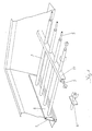
- the safety device consists of an angled area of the curb attached support profile 1, in the shown in Condition a cover profile 6 is hooked and locked.
- the Cover profile 6 takes safety tubes 2 at their ends.
- the Safety tubes 2 run across the roof opening and go through at a distance from the support or support profile 1, 6 a support web 11 running over them.
- This Support web 11 increases the stability on the one hand as a load distributor the arrangement and on the other hand prevents bending apart of tubes 2.
- the tubes 2 are fixed except for those for locking connected to the support bar, freely rotatable in their recordings stored in the cover profile 6 and in the support web 11, as by the Arrows is indicated on the front tube shown.
- roller bars 5 record, which, as previously described, the burglar resistance increase because they saw through the pipes 2 and Prevent support web 11.
- the roller bar 5 is located in the support web 11 freely rotatable on the tubes 2. Also in the pipes 2 Roll rod 5 inserted freely rotatable.
- the upper hanging device consists of the one open at the top Longitudinal groove 3 on the support profile and the one protruding downwards Hook bar 7 on the cover profile.
- the attachment takes place on this Just put in the hook bar 7 of the Cover profile 6 in the longitudinal groove 3 from above.
- the locking bar 8 is located with their upper undercut behind the latching extension 9 of the Carrying profile 1 and is thus secured against being pulled out. Adequate tension is ensured by the elasticity of the respective components ensured.
- the dead weight of the safety device is in this state by the upper hanging device, i.e. the hook bar 7 and the longitudinal groove 3 held.
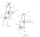
- FIG. 3 shows the arrangement from FIG. 2 in the state in a load on the pipe structure of the safety device works. Such a load is particularly caused by a heavy object or person exercised by the Safety device against falling through the roof opening is prevented.
Landscapes
- Engineering & Computer Science (AREA)
- Structural Engineering (AREA)
- Architecture (AREA)
- Civil Engineering (AREA)
- Emergency Lowering Means (AREA)
- Roof Covering Using Slabs Or Stiff Sheets (AREA)
- Tents Or Canopies (AREA)
- Buildings Adapted To Withstand Abnormal External Influences (AREA)
Claims (12)
- Dispositif de protection pour une ouverture de toita) avec des tubes de protection ou barreaux de protection (2) ou d'un treillis d'acier apte à être fixé aux parois latérales de l'ouverture de toit, en particulier d'une couronne de pose,b) avec des profilés porteurs (1) fixés mécaniquement aux parois latérales intérieures de l'ouverture de toit, etc) avec des profilés de recouvrement (6) qui sont dotés de logements pour maintenir de manière protégée les barreaux de protection, les tubes de protection (2) ou le treillis d'acier, et qui après l'accrochage élastique sur les profilés porteurs (1), recouvrent la fixation mécanique,
caractérisé en ce qued) les profilés de recouvrement (6) sont fixés sur les profilés porteurs (1) par suspension des profilés de recouvrement (6) dans la zone longitudinale supérieure et par accrochage élastique sur leur bord longitudinal inférieur. - Dispositif de protection selon la revendication 1,
caractérisé en ce que les profilés porteurs (1) sont des profilés allongés plats et les profilés de recouvrement (6) sont des profilés à contour essentiellement de même longueur, les deux profilés présentant tant dans leur zone de bordure longitudinale supérieure que dans leur zone de bordure longitudinale inférieure des dispositifs de suspension ou d'accrochage élastique (3, 7, 8, 9, 10). - Dispositif de protection selon l'une des revendications 1 ou 2, caractérisé en ce que le dispositif de suspension (3, 7) prévu sur le profilé porteur (1) et s'étendant sur son bord longitudinal supérieur est constitué d'une rainure longitudinale (3) ouverte vers le haut et sur le profilé de recouvrement (6) d'une latte d'accrochage (7), tandis que le dispositif d'accrochage élastique (8, 9, 10) qui s'étend sur le bord longitudinal inférieur est constitué sur le profilé porteur (1) d'une rainure d'accrochage élastique (9, 10) dotée d'une saillie supérieure et d'une saillie inférieure d'accrochage élastique (9, 10) et sur le profilé de recouvrement (6) d'une latte d'accrochage élastique (8) qui peut être amenée à engager les saillies d'accrochage élastique (9, 10).
- Dispositif de protection selon l'une des revendications 1 à 3, caractérisé en ce que le profilé de recouvrement (6) est un profilé à contour rabattu en dièdre dans sa zone centrale.
- Dispositif de protection selon l'une des revendications 1 à 4, caractérisé en ce que les logements pour les barreaux ou tubes de protection (2) ou pour les extrémités des barreaux du treillis d'acier sont configurés en forme de trous oblongs dans le profilé de recouvrement (6).
- Dispositif de protection selon l'une des revendications 1 à 5, caractérisé en ce que la latte porteuse (1) est dotée d'alésages pour le passage de moyens de fixation, en particulier des vis ou des rivets.
- Dispositif de protection selon l'une des revendications 1 à 6, caractérisé en ce que la latte porteuse (1) est fixée par collage ou par des dispositions de jointoyage à effet similaire sur la paroi latérale intérieure de l'ouverture de toit.
- Dispositif de protection selon l'une des revendications 1 à 7, caractérisé en ce que les barreaux ou tubes (2) sont protégés contre une extraction hors des logements derrière leur point de traversée du profilé de recouvrement par des moyens de fixation (12), de préférence des anneaux de serrage, des écrous, des rivets à entaille, des tiges à entaille ou similaires.
- Dispositif de protection selon l'une des revendications 1 à 8, caractérisé en ce qu'au moins une traverse de soutien (11) s'étend transversalement par rapport aux barreaux ou tubes de protection (2), à travers lesquels passent les barreaux ou tubes (2).
- Dispositif de protection selon la revendication 9, caractérisé en ce que la traverse de soutien (11) est un barreau plat avec alésages de passage pour les barreaux ou tubes.
- Dispositif de protection selon la revendication 2, caractérisé en ce que la traverse de soutien (11) présente une section transversale creuse, en particulier une section transversale en forme de U et des alésages de passage pour les barreaux ou les tubes.
- Dispositif de protection selon l'une des revendications 1 à 11, caractérisé en ce qu'un barreau rond (5) est installé dans les barreaux ou tubes de protection (2) et/ou dans la traverse de soutien creuse (11).
Priority Applications (4)
| Application Number | Priority Date | Filing Date | Title |
|---|---|---|---|
| DE59607501T DE59607501D1 (de) | 1996-05-14 | 1996-05-14 | Sicherungsvorrichtung für Dachdurchbrüche |
| EP96107672A EP0807724B1 (fr) | 1996-05-14 | 1996-05-14 | Dispositif de sécurité pour ouvertures de lucarne |
| AT96107672T ATE204356T1 (de) | 1996-05-14 | 1996-05-14 | Sicherungsvorrichtung für dachdurchbrüche |
| ES96107672T ES2171205T3 (es) | 1996-05-14 | 1996-05-14 | Dispositivo de seguridad para aberturas de tragaluz. |
Applications Claiming Priority (1)
| Application Number | Priority Date | Filing Date | Title |
|---|---|---|---|
| EP96107672A EP0807724B1 (fr) | 1996-05-14 | 1996-05-14 | Dispositif de sécurité pour ouvertures de lucarne |
Publications (2)
| Publication Number | Publication Date |
|---|---|
| EP0807724A1 EP0807724A1 (fr) | 1997-11-19 |
| EP0807724B1 true EP0807724B1 (fr) | 2001-08-16 |
Family
ID=8222780
Family Applications (1)
| Application Number | Title | Priority Date | Filing Date |
|---|---|---|---|
| EP96107672A Expired - Lifetime EP0807724B1 (fr) | 1996-05-14 | 1996-05-14 | Dispositif de sécurité pour ouvertures de lucarne |
Country Status (4)
| Country | Link |
|---|---|
| EP (1) | EP0807724B1 (fr) |
| AT (1) | ATE204356T1 (fr) |
| DE (1) | DE59607501D1 (fr) |
| ES (1) | ES2171205T3 (fr) |
Families Citing this family (1)
| Publication number | Priority date | Publication date | Assignee | Title |
|---|---|---|---|---|
| DK200000722A (da) * | 2000-05-02 | 2001-11-03 | Ts System As | Låsekasse |
Family Cites Families (5)
| Publication number | Priority date | Publication date | Assignee | Title |
|---|---|---|---|---|
| DE3108394A1 (de) * | 1981-03-05 | 1982-10-21 | Boris 8044 Unterschleißheim Fipke | "vorrichtung zur sicherung von dachluken gegen einbruch" |
| US4967509A (en) * | 1990-01-05 | 1990-11-06 | Storey Leonard M | Security window shutter |
| DE9104661U1 (de) * | 1991-04-17 | 1991-11-07 | Stiels, Hans, 4040 Neuss | Fenster o.dgl. |
| DE9210122U1 (de) * | 1992-07-28 | 1993-09-16 | Stiels, Hans, 41460 Neuss | Spezialgitter für Bauwerksöffnungen |
| GB9413096D0 (en) * | 1994-06-29 | 1994-08-17 | Metaform Ltd | Security grating assembly and bars |
-
1996
- 1996-05-14 DE DE59607501T patent/DE59607501D1/de not_active Expired - Lifetime
- 1996-05-14 ES ES96107672T patent/ES2171205T3/es not_active Expired - Lifetime
- 1996-05-14 EP EP96107672A patent/EP0807724B1/fr not_active Expired - Lifetime
- 1996-05-14 AT AT96107672T patent/ATE204356T1/de not_active IP Right Cessation
Also Published As
| Publication number | Publication date |
|---|---|
| EP0807724A1 (fr) | 1997-11-19 |
| ES2171205T3 (es) | 2002-09-01 |
| DE59607501D1 (de) | 2001-09-20 |
| ATE204356T1 (de) | 2001-09-15 |
Similar Documents
| Publication | Publication Date | Title |
|---|---|---|
| DE69729138T2 (de) | Sicherheitsverschluss | |
| EP0443441B1 (fr) | Grillage | |
| DE202014101111U1 (de) | Rollladenkasten | |
| DE202006007690U1 (de) | Zaun aus Zaunpfosten und Gittermatten | |
| EP0807724B1 (fr) | Dispositif de sécurité pour ouvertures de lucarne | |
| DE4437319A1 (de) | Einbruchhemmender Schirm für ein Wandelement, einbruchhemmendes Wandelement und einbruchhemmende Wand | |
| EP0778378B1 (fr) | Dispositif de sécurité pour ouvertures de toit et procédé de fabrication de ce dispositif | |
| DE19755762C2 (de) | Sicherungsgitter | |
| DE2849878C2 (de) | Einbruchsicherung für Gitterroste | |
| DE4320673C2 (de) | Leibungsrahmen für Fenster | |
| EP3916191B1 (fr) | Système de fixation d'une unité fonctionnelle pour un dispositif d'ombrage de l'ouverture d'un bâtiment dans un ensemble de fixation | |
| DE102012020025A1 (de) | Einbruchsicherung für ein Fenster oder eine Türe | |
| DE4421614C2 (de) | Fassadenverkleidung | |
| DE3920108C1 (fr) | ||
| EP1396605A2 (fr) | Fermeture pour orifices muraux | |
| DE202004005544U1 (de) | Zaunstecksystem | |
| EP0807725A1 (fr) | Dispositif de sécurité pour ouvertures de lucarne | |
| DE10062298B4 (de) | Vorrichtung zum vorübergehenden Einsetzen in eine Tür- oder Fensteröffnung | |
| DE9210122U1 (de) | Spezialgitter für Bauwerksöffnungen | |
| DE102005055061B4 (de) | Befestigungssystem für Sicherheitszäune | |
| DE202006004802U1 (de) | Rankgitter für Begrünungszwecke o.dgl. | |
| DE102023107531A1 (de) | Zaun- oder Torelement | |
| DE8622301U1 (de) | Gitter | |
| DE19545910C2 (de) | Vorrichtung zur Sicherung von Dachdurchbrüchen | |
| EP4205871A2 (fr) | Dispositif de raccordement |
Legal Events
| Date | Code | Title | Description |
|---|---|---|---|
| PUAI | Public reference made under article 153(3) epc to a published international application that has entered the european phase |
Free format text: ORIGINAL CODE: 0009012 |
|
| 17P | Request for examination filed |
Effective date: 19960514 |
|
| AK | Designated contracting states |
Kind code of ref document: A1 Designated state(s): AT BE CH DE ES FR GB IT LI LU NL |
|
| 17Q | First examination report despatched |
Effective date: 19990915 |
|
| GRAG | Despatch of communication of intention to grant |
Free format text: ORIGINAL CODE: EPIDOS AGRA |
|
| GRAG | Despatch of communication of intention to grant |
Free format text: ORIGINAL CODE: EPIDOS AGRA |
|
| GRAG | Despatch of communication of intention to grant |
Free format text: ORIGINAL CODE: EPIDOS AGRA |
|
| GRAH | Despatch of communication of intention to grant a patent |
Free format text: ORIGINAL CODE: EPIDOS IGRA |
|
| GRAH | Despatch of communication of intention to grant a patent |
Free format text: ORIGINAL CODE: EPIDOS IGRA |
|
| GRAA | (expected) grant |
Free format text: ORIGINAL CODE: 0009210 |
|
| ITF | It: translation for a ep patent filed | ||
| AK | Designated contracting states |
Kind code of ref document: B1 Designated state(s): AT BE CH DE ES FR GB IT LI LU NL |
|
| REF | Corresponds to: |
Ref document number: 204356 Country of ref document: AT Date of ref document: 20010915 Kind code of ref document: T |
|
| REG | Reference to a national code |
Ref country code: CH Ref legal event code: EP |
|
| GBT | Gb: translation of ep patent filed (gb section 77(6)(a)/1977) |
Effective date: 20010816 |
|
| REF | Corresponds to: |
Ref document number: 59607501 Country of ref document: DE Date of ref document: 20010920 |
|
| REG | Reference to a national code |
Ref country code: CH Ref legal event code: NV Representative=s name: RIEDERER HASLER & PARTNER PATENTANWAELTE AG |
|
| ET | Fr: translation filed | ||
| REG | Reference to a national code |
Ref country code: GB Ref legal event code: IF02 |
|
| PG25 | Lapsed in a contracting state [announced via postgrant information from national office to epo] |
Ref country code: LU Free format text: LAPSE BECAUSE OF NON-PAYMENT OF DUE FEES Effective date: 20020514 Ref country code: GB Free format text: LAPSE BECAUSE OF NON-PAYMENT OF DUE FEES Effective date: 20020514 Ref country code: AT Free format text: LAPSE BECAUSE OF NON-PAYMENT OF DUE FEES Effective date: 20020514 |
|
| PG25 | Lapsed in a contracting state [announced via postgrant information from national office to epo] |
Ref country code: ES Free format text: LAPSE BECAUSE OF NON-PAYMENT OF DUE FEES Effective date: 20020515 |
|
| PG25 | Lapsed in a contracting state [announced via postgrant information from national office to epo] |
Ref country code: LI Free format text: LAPSE BECAUSE OF NON-PAYMENT OF DUE FEES Effective date: 20020531 Ref country code: CH Free format text: LAPSE BECAUSE OF NON-PAYMENT OF DUE FEES Effective date: 20020531 Ref country code: BE Free format text: LAPSE BECAUSE OF NON-PAYMENT OF DUE FEES Effective date: 20020531 |
|
| PLBE | No opposition filed within time limit |
Free format text: ORIGINAL CODE: 0009261 |
|
| STAA | Information on the status of an ep patent application or granted ep patent |
Free format text: STATUS: NO OPPOSITION FILED WITHIN TIME LIMIT |
|
| 26N | No opposition filed | ||
| REG | Reference to a national code |
Ref country code: ES Ref legal event code: FG2A Ref document number: 2171205 Country of ref document: ES Kind code of ref document: T3 |
|
| PG25 | Lapsed in a contracting state [announced via postgrant information from national office to epo] |
Ref country code: NL Free format text: LAPSE BECAUSE OF NON-PAYMENT OF DUE FEES Effective date: 20021201 |
|
| GBPC | Gb: european patent ceased through non-payment of renewal fee |
Effective date: 20020514 |
|
| REG | Reference to a national code |
Ref country code: CH Ref legal event code: PL |
|
| PG25 | Lapsed in a contracting state [announced via postgrant information from national office to epo] |
Ref country code: FR Free format text: LAPSE BECAUSE OF NON-PAYMENT OF DUE FEES Effective date: 20030131 |
|
| NLV4 | Nl: lapsed or anulled due to non-payment of the annual fee |
Effective date: 20021201 |
|
| REG | Reference to a national code |
Ref country code: FR Ref legal event code: ST |
|
| REG | Reference to a national code |
Ref country code: ES Ref legal event code: FD2A Effective date: 20030611 |
|
| PG25 | Lapsed in a contracting state [announced via postgrant information from national office to epo] |
Ref country code: IT Free format text: LAPSE BECAUSE OF NON-PAYMENT OF DUE FEES Effective date: 20050514 |
|
| PGFP | Annual fee paid to national office [announced via postgrant information from national office to epo] |
Ref country code: DE Payment date: 20140521 Year of fee payment: 19 |
|
| REG | Reference to a national code |
Ref country code: DE Ref legal event code: R119 Ref document number: 59607501 Country of ref document: DE |
|
| PG25 | Lapsed in a contracting state [announced via postgrant information from national office to epo] |
Ref country code: DE Free format text: LAPSE BECAUSE OF NON-PAYMENT OF DUE FEES Effective date: 20151201 |