EP0807873A1 - Verfahren und Vorrichtung zur Angabe des Zeitpunkts, an welchem ein bestimmter Prozess stattfand - Google Patents
Verfahren und Vorrichtung zur Angabe des Zeitpunkts, an welchem ein bestimmter Prozess stattfand Download PDFInfo
- Publication number
- EP0807873A1 EP0807873A1 EP97107879A EP97107879A EP0807873A1 EP 0807873 A1 EP0807873 A1 EP 0807873A1 EP 97107879 A EP97107879 A EP 97107879A EP 97107879 A EP97107879 A EP 97107879A EP 0807873 A1 EP0807873 A1 EP 0807873A1
- Authority
- EP
- European Patent Office
- Prior art keywords
- time
- information
- transmitter
- measuring
- receiver
- Prior art date
- Legal status (The legal status is an assumption and is not a legal conclusion. Google has not performed a legal analysis and makes no representation as to the accuracy of the status listed.)
- Granted
Links
- 238000000034 method Methods 0.000 title claims abstract description 95
- 230000005540 biological transmission Effects 0.000 claims abstract description 34
- 238000012545 processing Methods 0.000 description 53
- 238000005259 measurement Methods 0.000 description 27
- 238000011282 treatment Methods 0.000 description 9
- 238000010586 diagram Methods 0.000 description 7
- 230000036772 blood pressure Effects 0.000 description 6
- 230000006870 function Effects 0.000 description 5
- 230000036760 body temperature Effects 0.000 description 4
- 230000001360 synchronised effect Effects 0.000 description 4
- 238000004891 communication Methods 0.000 description 3
- 238000013500 data storage Methods 0.000 description 3
- 238000003745 diagnosis Methods 0.000 description 3
- 238000012986 modification Methods 0.000 description 3
- 230000004048 modification Effects 0.000 description 3
- 238000004364 calculation method Methods 0.000 description 2
- 230000009545 invasion Effects 0.000 description 2
- 238000009825 accumulation Methods 0.000 description 1
- 238000006243 chemical reaction Methods 0.000 description 1
- 238000012544 monitoring process Methods 0.000 description 1
- 230000003287 optical effect Effects 0.000 description 1
Images


Classifications
-
- G—PHYSICS
- G04—HOROLOGY
- G04G—ELECTRONIC TIME-PIECES
- G04G99/00—Subject matter not provided for in other groups of this subclass
Definitions
- the present invention relates to devices and methods for specifying a time when a specified process was performed and more particularly to electronic devioces and methods for specifying a time when a specified process was performed, and transmitters and receivers for use in the electronic devices.
- some electronic devices such as facsimile devices/pagers which record/store the time when they receive/transmit data from/to other electronic devices.
- the electronic device which stores the time when it transmits data the time output from a clock circuit provided in the electronic device thereof is used whereas in the case of the electronic device which stores the time when it receives data, the time output from a clock circuit provided in the electronic device is used.
- the obtained target data and the data on the time when the target data was obtained ares temporarily stored in a memory and then transmitted to the requesting end.
- a time when an image was picked up by an electronic still camera having a communication function can be desired to be sent along with the picked-up image.
- a clock circuit When data on the time when such data to be sent is stored and sent, a clock circuit is required to be provided at the transmitting end. In this case, the time recorded by the clock circuit is required to be accurate at all times.
- the sending and receiving ends are required to be synchronized.
- the transmitting and receiving ends are required to be synchronized or corrected with respect to time at all times, which is very troublesome.
- living body data measuring devices are required for the respective measuring items, for example, if separate devices such as electrocardiograms and pulse meters measure the corresponding data and send same, in an in-home examination and treatment, the respective devices are required to be synchronized, which is a very troublesome work.
- Another object of the present invention is to provide electronic devices and methods which eliminate troublesome synchronization between the transmitter and receiver even when current time measuring means is provided at the transmitter, and transmitters, receivers and storage mediums involved in those electronic devices.
- an electronic device comprising:
- the transmitter transmits the receiver time difference information indicative of the difference between the time measured by the time measuring means when the time difference information is transmitted to the receiver and the time when the specified processing was performed with information on the latter time being stored in the time information storage means.
- the receiver calculates the time when the transmitter performed the special processing, on the basis of the received time difference information and the current time information obtained from the time measuring means. Thus, even when no current time measuring (or recording) means is provided at the transmitter, the time when the specified processing was performed is specified.
- the inventive electronic devices apply to in-home examination and treatment systems, communication devices such as facsimile devices/pagers which receive and indicate the time when the other party sent data, and image storage devices such as digital cameras.
- communication devices such as facsimile devices/pagers which receive and indicate the time when the other party sent data
- image storage devices such as digital cameras.
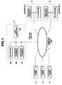
- FIG. 1 is a block diagram of an in-home examination and treatment system as an embodiment of the present invention.
- reference numeral 1 denotes a general public (telephone) line.
- Reference numeral 2 denotes a patient's home which is connected over the general public line 1 to the medical center 3 to be described later in more detail.
- a home device which sends the medical center 3 a series of measured living body data such as the patient's blood pressure, body temperature, pulses and cardiogram waveform and the corresponding data on the respective time when those data were measured.
- the structure of the home device will be described in more detail later.
- the medical center 3 is comprised of a host computer 3a connected via a private line NT to the general public line 1, a business terminal 3b connected to the host computer 3a, a doctor's terminal 3c and a telephone set 3d.
- the host computer 3a supervises and controls transmission/receipt of data between the patient's home 2 and the medical facilities 4 over the general public line 1. More specifically, the host computer 3a stores data on the patient's living body up-loaded by the patient's home 2 and sends patient's data to the medical facilities 4 in accordance with a down-load request from the medical facilities 4.
- Medical facilities 4 such as a hospital or a clinic, include a doctor's terminal 4a and a telephone set 4b.
- the medical facilities 4 use the doctor's terminal 4a to access the host computer 3a over the general public line 1 to thereby down load appropriate data on the patient and examine the patient.
- the patient's home 2 transmits the patient's living body data to the medical center 3, which sends the living body data to the medical facilities 4 for diagnosing purposes.
- the medical facilities transmit to the patient's 2 and the medical center 3 data on a method of treatment appropriate for the patient, etc.
- the doctor is able to handle the patient's living body data as a time-series history on the basis of the storage data in the medical center 3, so that the doctor is able to make a medical examination and treatment similar to his or her regular rounds without the need for on-line monitoring.
- the patient is able to receive the doctor's diagnosis even at his or her home whereas the doctor is able to examine the patient at his or her home between interview examinations/treatments of other patients in the hospital.
- the structure of the home device which handles a patient's living body data as a time series history and sends the data to the host computer 3a will be described with reference to FIGS. 2-5.
- FIG. 2 is a block diagram of the whole structure of a home device provided in a patient's home 2.
- reference numeral 20 denotes a telephone set
- reference numerals 21-1 to 21-N each denote a device which measures the patient's blood pressure, body temperature, pulses, cardiogram waveform, etc.
- Those devices send by radio data which includes the respective measured living body data and corresponding time difference data DT (to be described later).
- Reference numeral 22 denotes a patient terminal which receives the respective data sent by radio from the corresponding measuring devices 21-1 to 21-N, and converts the respective received data to time-series living body data on the basis of the corresponding time difference data DT. That is, data on the respective times when the corresponding living body data were measured are added to the corresponding living body data.
- the patient terminal 22 then modulates those-series data to provide a voice signal, which is then sent over the general public line 1 to the host computer 3a.
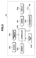
- each of the measuring devices 21-1 to 21-N has a structure shown by reference numeral 21 in FIG. 3.
- Those measuring devices are different one from another only in that a sensor depending on an object to be measured is used and that a measuring circuit especially constituted so as to obtain data on the object to be measured is used.
- reference numeral 21a denotes a sensor for an item to be measured.
- a cuff, pressure sensor or an optical sensor is used as sphygmomanometer.
- Reference numeral 21b denotes a measuring circuit which appropriately amplifies the output of the sensor 21a, filters out possible noise contained in the sensor output, performs an A/D conversion on the filtered-out output, and then outputs the resulting living body data (for example, blood pressure data in the case of a sphygmomanometer).
- a reference numeral 21c denotes a controller which includes a CPU, ROM, etc., and executes a control program stored in the ROM to control the respective elements concerned of the measuring device.
- the controller 21c has a timer function to measures or records time. Each time the controller 21c gets living body data, it adds measured time (timer value) data to the living body data and writes them into a memory (RAM) 21e, the register structure of which will be described later.
- Reference numeral 21d denotes a key-in unit composed of a plurality of key switches such as a power source on/off key and a measurement start instructing key to thereby give key inputs depending on the respective operations of the key switches concerned to the controller 21c, which performs respective processing operations depending on the corresponding key inputs.
- Reference numeral 21f denotes a driver which drives a display unit 21g composed of an LCD panel depending on a display control signal delivered from the controller 21c.
- Reference numeral 21h denotes a transmitter which modulates data outputted from the controller 21c and then transmits the modulated data by radio from an antenna A0 to a patient terminal to be described in more detail later.
- the data from the controller 21c is composed of living body data and data on a time difference DT obtained by calculation, which will be described later in more detail, and added to the living body data.
- reference character MID denotes a register which stores identification data representing items to be measured such as a patient's blood pressure, body temperature or cardiogram waveform.
- the identification data may be stored in the ROM (not shown) of the controller 21c.
- a reference character DR denotes a display register which stores various display data displayed on the display unit 21g. Depending on the contents of the display register DR, the controller 21c generates a display control signal to be fed to the driver 21f.
- Reference character F denotes a measuring flag register in which "1" represents measurement whereas "0" represents stop of the measurement.
- Reference character L denotes a measurement count register which makes a round at a period of six measurements in this embodiment. The value of the measurement count register L also functions as an address pointer for data registers M0-M5 to be described later in more detail.
- Reference character T denotes a time measurement register which stores a measured time (timer value) obtained by sequentially incrementing a timer clock which is obtained by dividing the frequency of an internal clock.
- the data registers M0-M5 store in corresponding relationship the measured living body data D(0)-D(5) and data on the respective time values (timer values) T(0)-T(5) when those living data D(0)-D(5) were measured. Data on the measured time values (timer values) T(0)-T(5) are referenced when time difference data DT to be added to the respective living body data D(0)-D(5) are calculated.
- the data in those data registers M0-M5 make a round at a period of six measurements and are thereafter overwritten sequentially with sequentially measured data.
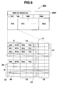
- FIG. 5 is a block diagram of the structure of the patient terminal 22.
- reference numeral 22a denotes a receiver which receives through an antenna A1 and demodulates the data sent by radio from a measuring device 21.
- the demodulated data is inputted to the controller 22b, which is composed of a CPU, a ROM, etc., and controls the respective elements of the terminal.
- the features of the operation of the controller 22b are that it separates the data fed from the receiver 22a into living body data and its time difference data DT, calculates on the basis of the time difference data DT the time when the living body data was measured, so that the living body data may be handled as a time-series history.
- Reference numeral 22c denotes a key-in unit which includes a power source turn on/off key, a receive key which instructs the start of data receipt, a send key which instructs the start of data transmission, etc.
- a key input depending on the operation of each key is given to the controller 22b, which performs a processing operation depending on the key input.
- Reference numeral 22d denotes a memory (RAM) used as a work area which temporality stores the respective data transmitted from the corresponding measuring devices 21-1 to 21-N or stores living body data of a time-series history to which the temporality stored data is converted, under control of the controller 22b.
- RAM random access memory
- Reference numeral 22e denotes a driver which drives a display unit 22f composed of an LCD panel, depending on a display control signal from the controller 22b.
- Reference numeral 22g denotes a transmitter which FSK-modulates the data or the living body data to which the measurement time data is added, outputted from the controller 22b and transmits the resulting data over the general public line 1 to the host computer 3a.
- reference character DSP denotes a display register which stores various display data to be displayed on the display unit 22f.
- the controller 22b Depending on the contents of the display register DSP, the controller 22b generates a display control signal to be fed to the driver 22e.
- Reference character J denotes a transmit/receive flag register in which "1" represents transmission whereas "0" represents receipt.
- Reference character ID denotes a patient identification register which stores an identification code allocated to each patient.
- Reference character TEL denotes a register which stores the telephone number of a medical center to which the data is to be sent.
- Reference character TMP denotes an identification temporary storage register which stores identification data in a measuring device 21 to be received.
- Reference character TIME denotes a current time register which records and stores the current time (date, time).
- Reference characters E(0)-E(N) denote measured data register areas provided for the respective measuring devices 21-1 to 21-N to store transmit data for the respective measurement items (for example, blood pressure, body temperature, pulses and cardiogram waveform) and time-series living body data whose measurement times are specified on the basis of the respective transmit data.
- Each of the measured data register areas E(0)-E(N) has 11 storage areas N, L0, L2, L3, ..., L9, and a transmission data area S.
- Received six pairs of time-series living body item data and corresponding time difference data D(0) and DT(0); D(1) and DT(1); D(2) and DT(2); D(3) and DT(3); D(4) and DT(4); and D(5) and Dt(5), transmitted by a single operation of a measuring device 21, are stored in the storage area N of six registers.
- the respective time difference data DT(0), DT(1), DT(2), ... , DT(5) are converted to corresponding time data T(0), T(1), T(2), ... , T(5) representing the times when the respective living body data were obtained.
- the resulting six pairs of time-series living body item data and corresponding time data D(0) and T(0); D(1) and T(1); ... ; and D(5) and T(5) are stored in the storage area L1.
- the next received six pairs of time-series living body item data and corresponding time difference data D(0) and DT(0); D(1) and DT(1); D(2) and DT(2); D(3) and DT(3); D(4) and DT(4); and D(5) and Dt(5), transmitted by the next single operation of the measuring device 21, are similarly stored in the storage area N of six registers.
- the resulting six pairs of time-series living body item data and corresponding time data similar to those stored in the storage area L0 are now stored in the storage area L1 and so forth.
- the transmit data area S is composed of registers S0-S5 which store corresponding transmit data, which are transmitted over the telephone line to the medical center 3.
- the controller 21c reads a predetermined control program from its internal ROM, and executes a measuring routine of FIG. 7 to advance its processing to step SA1, where the controller performs initialization which includes clearing to 0 data in the memory 21e and the respective internal registers or flag setting, and then advances its processing to step SA2.
- step SA1 the controller 21c starts up its timer function to generate a timer clock, for example, at intervals of one second (not shown in FIG. 7).
- step SA2 the controller determines whether a time measuring timing has occurred or the timer clock has been detected. If so (YES at step SA2), the controller advances its processing to step SA3, where the controller increments by one the timer value in the time measuring register T of the memory 21c and then returns its processing to step SA2.
- step SA4 the controller determines whether a measure key which instructs the start of the measurement has been operated. For example, when the measure key is operated in a state where the sensor 21a is set on the patient, the result of the determination at step SA4 becomes YES and the controller advances its processing to step SA5, where the controller performs measurement/storage.
- the signal measured by the sensor 21a is converted by the measuring circuit 21b to living body data D(0), which is then stored along with data on the measured elapsed time (time value) T(d) when the data D(0) was measured in the data register M0 (FIG. 4) of the memory 21e under the control of the controller 21c.
- step SA6 the controller determines whether there is any previous data.
- the controller since the measurement is a first one, the result of the determination at step SA6 is NO, and the controller advances its processing to step SA7, where the controller clears the measured elapsed time data (timer value) T(0) stored in the data register M0, and hence the timer difference DT.
- step SA8 the controller 21c increments by one the value of the measurement count register L and sets an address pointer in the data register M1. Thereafter, the controller advances its processing to step SA9, where the controller 21c sets the living body data D(0) stored in the data register M0, in the display register DR to display the result of the measurement on the display unit. Then, the controller 21c again returns its processing to step SA2, and, when the time measuring timing has not occurred, then advances its processing to step SA4, where the controller determines whether the measure key is on. If so, the controller performs the next measurement/storage at step SA5.
- step SA5 the controller performs the processing at step SA5 and then advances its processing to step SA6.
- the measurement is not the first one, so that the result of the determination at step SA6 becomes YES.
- the controller then advances its processing to step SA10, where the controller stores data on the measured elapsed time (timer value) T(1) when the second measurement was made, along with the corresponding living body data D(1) in the data register M1.
- the transmit key which instructs the start of data transmission is operated to send those data to the patient terminal 22.
- the controller determines whether the transmit key has been operated.
- step SA11 the controller advances its processing to step SA12, where the controller performs a time difference calculation process which includes subtraction of the respective second-sixth measured elapsed times when the corresponding living body data were measured from the elapsed time measured in the time measurement register T representing the starting of the data transmission to obtain the corresponding time differences DT(1)-DT(5), and replacement of the measured time values T(1)-T(5) with the corresponding time differences DT(1)-DT(5) in the memory 21e.
- the controller then advances its processing to step SA13, where it transfers to the transmitter 21h the identification data MED, living body data D(0)-D(5), and corresponding time difference data DT(0)-DT(5), stored in the memory 21e and the transmitter 21h transmits by radio those data and data on the number of those data pairs to the patient terminal 22 by radio such that the respective pairs of data D(0), DT(0); D(1), DT(1); D(2), DT(2); ... ; D(5), DT(5) may be recognized separately.
- step SA14 the controller displays on the display unit 21g that the transmission has ended, and then returns its processing to step SA2.
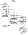
- the controller 22b reads a predetermined control program stored in its internal ROM and executes a terminal processing routing of FIG. 8. First, the controller advances its processing to step SB1, where the controller performs initialization which includes clearing the memory 22d and the respective internal registers of the terminal 22 and/or flag setting, and then advances its processing to step SB2.
- step SB2 determines whether there is any received data. If so, the controller advances its processing to step SB3, where the controller determines whether the transmit/receive flag J is "0" or a receive mode has been set by the operation of the transmit/receive mode switching key. If so, the result of the determination at step SB3 becomes YES, and the controller advances its processing at step SB3, where the controller performs the receiving process at step SB4 as shown by a receiving process routine of FIG. 9.
- step SC1 the controller temporarily stores in the memory 21d the data transmitted by the measuring device 21 and received by the receiver 22a. More specifically, of the received data, the controller stores the identification data MID in the identification temporary storage register TMP, and living body data D(0)-D(5) and corresponding time difference data DT(0)-DT(5) in the received data storage area N (FIG. 6) of the appropriate one of the measurement register areas E(0)-E(N) corresponding to the identification data MID.
- the controller 22b then advances its processing to step SC2, where the controller sequentially reads the time difference data DT(0)-DT(5) stored in the received data storage area N, subtracts corresponding respective time differences from the current time whose data is recorded in the current time register TIME, specifies the times T(0)-T(5) when the respective living body data D(0)-D(5) are measured and replaces the respective data on the time difference DT(0)-DT(5) data stored in the received data storage area N with the times T(0)-T(5).
- the living body data D(0)-D(5) and the corresponding specified measurement time T(0)-T(5) data added to the former data D(0)-D(5) are transferred to and stored in the transmission data area S (FIG. 6).
- step SC3 the controller performs a data checking process in a conventional manner.
- step SC4 if the data checking process clarifies that the living body data D(0)-D(5) and the corresponding measured times are normal and can be handled as a time-series history, the controller sequentially stores those data as correct in any appropriate one of the storage areas L0-L9. Thereafter, the controller 22b returns its processing to the terminal processing routine of FIG. 8. In this routine, the controller advances its processing to step SB5, where the controller displays the normal data obtained in the receiving routine on the display unit 22f. Thereafter, the controller 22b again advances its processing to step SB2.
- step SB2 When there is no received data, the result of the determination at step SB2 is NO, and the controller advances its processing to step SB6, where the controller determines whether the time measuring timing has occurred. If so, the result of the determination at step SB6 becomes YES and the controller advances its processing to step SB7, where the controller increments the data in the current time register TIME of the memory 22d to update the current date and time (hours, minutes, seconds), updates the display register accordingly, and at step SB5, displays the current date and time on the display unit 22f.
- step SB6 determines at step SB6 that the time measuring timing has not occurred (NO at step SB6)
- the controller advances its processing to step SB8, where the controller determines whether there is any key operated.
- step SB8 When the transmit key is operated to transmit to the medical center 3 (FIG. 1) normal data for the respective measurement items obtained by the receiving routine, the result of the determination at step SB8 becomes YES. Thus, the controller advances its processing to step SB9, where the controller determines whether the transmit key has been operated. In this case, since the transmit key has been operated, the result of the determination at step SB9 becomes YES and the controller advances its processing to step SB10.
- step SB14 the controller performs a process corresponding to that operated key.
- the controller sets the transmit/receive flag J at "1" in accordance with the operation of the transmit key. Thereafter, at step SB11, the controller performs a transmitting process in which the normal data or six pairs of living body data D(0)-D(5) and corresponding added measured time T(0)-T(5) data which can be handled as a time-series history stored in the registers S0-S5 of the area S are transmitted to the medical center 3 along with identification data which identify the respective measurement items and identification code of the register ID which identify the patient.
- the telephone number of the medical center 3 stored in the register TEL of the memory 22d is automatically dialed to establish communication with a predetermined protocol, and those data are then up loaded.
- the controller receives an up-load end signal as acknowledge signal from the medical center 3, and the result of the determination at step SB12 about whether the data transmission has ended becomes YES, and the controller advances its processing to step SB13, where the controller sets the transmit/receive flag J at "0" and hence sets the receive mode. Thereafter, the controller 22b returns its processing to step SB2 to repeat the process of FIG. 8.
- the measuring device 21 adds the time difference DT data to the measured living body data and outputs the resulting data by radio.
- the patient terminal 22 specifies the time when the living body data were measured on the basis of the received time difference data DT.
- the transmitting end is capable of storing and transmitting data on the time when the data to be transmitted were obtained, without providing current time measuring means at the transmitting end.
- the transmitting end (measuring device) has been illustrated as calculating the time difference between the time when the living body data were measured and the time when the measured data were transmitted and then transmitting the time difference data. If the transmitting end transmits data on the time in the time measuring register T when the living body data were measured and data on the time in the time measuring register T when the living body data, etc., were transmitted, the receiving end (patient device) will be able to calculate the time difference and calculate/specify the time where the living body data were measured.
- the transmitting end may store the time data in the time measuring register T where the living body data were measured until the transmission time, subtract the time in the time recording register T when the living body data were measured from the time in the time recording register T when the living body data, etc., are transmitted, and transmit data on the resulting time difference to the receiving end.
- current time recording means which is not required to be synchronized with the time recording means provided at the receiving end may be provided at the transmitting end.
- arrangement may be such that the measuring device 21 transmits to the receiving end data on the time T2 where the living body data were measured and data on the time T1 when the living body data is transmitted while the patient's device 22 calculates the time on the side of the receiving end corresponding to the time when the living body data were measured on the basis of the time difference (T1 -T2).
- the patient's living body data can be handled as a time-series history as well as synchronization between the measuring device 21 and the patient terminal 22 becomes useless.
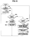
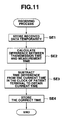
- FIG. 10 shows a flow chart indicative of the operation of the measuring device 21 whereas FIG. 11 shows a flow chart indicative of the receiving process of the patient terminal.
- step SD1 the controller determines whether the time measuring timing has occurred. If so, the controller advances its processing to step SD2, where the controller updates the current time data in the current time register TIME.
- step SD1 the controller advances its processing to step SD3, where the controller determines whether the measure key has been operated. If so, the controller advances its processing to SD4, where the controller performs a data measuring/storing operation. Thereafter, the controller advances its processing to step SD5, where the controller stores in the memory the time in the current time register TIME when the living body data was measured/stored, in correspondence to the measured data.
- step SD6 When the transmit key is operated, the controller determines at step SD6 that the transmit key has been operated, and the controller advances its processing to step SD7, where the controller transmits the measured data and the data on the time when the data was measured, both being stored in the memory. In this case, if a plurality of such measured data are stored, those data are transmitted along with the respective times where those data were measured. Thereafter, the controller advances its processing to step SD8, where the controller transmits the current time data stored in the current time register. Thereafter, the controller advances its processing to step SD9, where the controller displays that the data transmission has ended.
- the controller first stores received data temporarily at step SE1.
- the controller calculates from the received data the time differences between the time when the measured data were transmitted and the respective times when the living body data were measured. Thereafter, the controller advances its processing to step SE3, where the controller subtracts the time difference calculated at step SE2 from the current time in the clock of the patient terminal to obtain the accurate time when the living body data were measured, and then stores the measured data and corresponding data on the obtained accurate measurement time.
- the present invention is not limited to this particular case, and various changes and modification are possible.
- a timepiece such as a stopwatch which has the function of storing a timer value
- the time when some operation was performed may be specified on the basis of the stored timer value.
- a time difference between a stored timer value and the current measured time may be calculated and the time when the timer value was stored can be obtained.
- a well-known pager may similarly specify the time when the data was obtained.
- the present invention is also applicable even in a field of security.
- a system is considered in which (1) when a possible person's invasion is monitored, using a security camera, the fact of the person's invasion is detected from a change in the image in a camera, and (2) the time when this change occurred is specified and stored along with the image at that time.
- data on the time when the interphone is operated and a visitor's face image picked up at that time may be stored in a memory.
- the time when the image was previously stored in the memory is specified on the basis of the timer time when the image was stored in the memory and the timer time when the image data was read from the memory.
- the present invention is applicable to well-known digital cameras. For example, on the basis of the stored timer time when the image was picked up, the time when the picked-up image was printed out or displayed can be known.
Landscapes
- Physics & Mathematics (AREA)
- General Physics & Mathematics (AREA)
- Measuring And Recording Apparatus For Diagnosis (AREA)
- Telephonic Communication Services (AREA)
- Electric Clocks (AREA)
- Arrangements For Transmission Of Measured Signals (AREA)
Applications Claiming Priority (3)
| Application Number | Priority Date | Filing Date | Title |
|---|---|---|---|
| JP12122896 | 1996-05-16 | ||
| JP121228/96 | 1996-05-16 | ||
| JP12122896A JP3618169B2 (ja) | 1996-05-16 | 1996-05-16 | 電子機器および当該電子機器を用いたシステム |
Publications (2)
| Publication Number | Publication Date |
|---|---|
| EP0807873A1 true EP0807873A1 (de) | 1997-11-19 |
| EP0807873B1 EP0807873B1 (de) | 2002-03-13 |
Family
ID=14806079
Family Applications (1)
| Application Number | Title | Priority Date | Filing Date |
|---|---|---|---|
| EP97107879A Expired - Lifetime EP0807873B1 (de) | 1996-05-16 | 1997-05-14 | Verfahren und Vorrichtung zur Angabe des Zeitpunkts, an welchem ein bestimmter Prozess stattfand |
Country Status (4)
| Country | Link |
|---|---|
| US (2) | US6130860A (de) |
| EP (1) | EP0807873B1 (de) |
| JP (1) | JP3618169B2 (de) |
| DE (1) | DE69710941T2 (de) |
Cited By (3)
| Publication number | Priority date | Publication date | Assignee | Title |
|---|---|---|---|---|
| WO2001067420A1 (fr) * | 2000-03-07 | 2001-09-13 | Laserdynamics, Inc. | Procede de mesure et moyen de communication utilisant un systeme de service de mesure |
| EP1376304A3 (de) * | 2002-06-17 | 2004-01-28 | NTT DoCoMo, Inc. | Kommunikationsterminal zur Beschränken der Verwendung von Inhalten |
| US8176546B2 (en) | 2006-06-20 | 2012-05-08 | Nds Limited | Time information management system |
Families Citing this family (24)
| Publication number | Priority date | Publication date | Assignee | Title |
|---|---|---|---|---|
| KR100284897B1 (ko) * | 1998-02-02 | 2001-03-15 | 박성기 | 자동정보게시장치및게시방법 |
| JP3667142B2 (ja) * | 1999-03-12 | 2005-07-06 | シャープ株式会社 | 情報通信装置 |
| US6416471B1 (en) * | 1999-04-15 | 2002-07-09 | Nexan Limited | Portable remote patient telemonitoring system |
| JP5147147B2 (ja) * | 2000-09-13 | 2013-02-20 | 江藤電気株式会社 | 計測データ配信システム及びそれに用いる計測データ管理用コンピュータ装置 |
| JP2002181970A (ja) * | 2000-12-19 | 2002-06-26 | Nec Corp | 時刻管理装置 |
| JP5059260B2 (ja) * | 2001-03-29 | 2012-10-24 | 帝人株式会社 | 医療機器の遠隔監視方法 |
| WO2003001337A2 (en) * | 2001-06-22 | 2003-01-03 | Sekura Ronald D | Prescription compliance device and method of using device |
| JP4174430B2 (ja) * | 2004-02-06 | 2008-10-29 | ティーディーシーソフトウェアエンジニアリング株式会社 | 記録管理方法及び記録管理システム |
| JP4683857B2 (ja) * | 2004-05-11 | 2011-05-18 | 株式会社タダノ | 同時多点計測システム |
| US7865944B1 (en) * | 2004-09-10 | 2011-01-04 | Juniper Networks, Inc. | Intercepting GPRS data |
| JP4510584B2 (ja) * | 2004-10-28 | 2010-07-28 | 新日本製鐵株式会社 | 操業データ解析システム、解析方法、コンピュータプログラム、及び記録媒体 |
| JP4264955B2 (ja) | 2005-07-11 | 2009-05-20 | 株式会社Jm | 認証画像付き報告書作成システム |
| JP5003189B2 (ja) * | 2007-02-08 | 2012-08-15 | パナソニック株式会社 | 生体信号測定時刻修正システム |
| JP4823941B2 (ja) * | 2007-02-22 | 2011-11-24 | シャープ株式会社 | 情報測定装置、情報管理サーバ、情報管理システム、情報測定装置の制御方法、情報管理サーバの制御方法、情報管理プログラムおよびこれを記録したコンピュータ読み取り可能な記録媒体 |
| JP4610598B2 (ja) * | 2007-10-18 | 2011-01-12 | 株式会社タニタ | 通信システム、時刻付与装置、時刻受取装置、プログラム、時刻付与方法および時刻訂正方法 |
| JP5234079B2 (ja) * | 2010-10-01 | 2013-07-10 | オムロン株式会社 | センサ装置、センサ管理システム、センサ装置の制御方法、プログラム及びコンピュータ読み取り可能な記録媒体 |
| US9492341B2 (en) | 2010-10-08 | 2016-11-15 | Hill-Rom Services, Inc. | Hospital bed with graphical user interface having advanced functionality |
| JPWO2013137067A1 (ja) * | 2012-03-15 | 2015-08-03 | 日本電気株式会社 | 演算装置、演算方法及び演算プログラム |
| US9240120B2 (en) | 2013-03-15 | 2016-01-19 | Hill-Rom Services, Inc. | Caregiver rounding with real time locating system tracking |
| JP7086541B2 (ja) | 2017-08-09 | 2022-06-20 | オムロンヘルスケア株式会社 | データ受信装置、データ送信装置およびデータ伝送システム |
| US10861598B2 (en) | 2018-02-14 | 2020-12-08 | Hill-Rom Services, Inc. | Historical identification and accuracy compensation for problem areas in a locating system |
| JP6980589B2 (ja) * | 2018-03-28 | 2021-12-15 | テルモ株式会社 | 生体情報測定装置及び生体情報測定システム |
| JP7251263B2 (ja) * | 2019-03-28 | 2023-04-04 | オムロンヘルスケア株式会社 | 測定機器 |
| US11699517B2 (en) | 2019-08-30 | 2023-07-11 | Hill-Rom Services, Inc. | Ultra-wideband locating systems and methods |
Citations (3)
| Publication number | Priority date | Publication date | Assignee | Title |
|---|---|---|---|---|
| US4057785A (en) * | 1975-03-14 | 1977-11-08 | Westinghouse Electric Corporation | Sequence of events recorder and system for transmitting sequence data from a remote station to a master station |
| EP0077249A1 (de) * | 1981-10-09 | 1983-04-20 | Compagnie Europeenne De Teletransmission C.E.T.T. | Zeitmessungsverfahren, zentralisiertes Verwaltungssystem mit diesem Verfahren und seine Anwendung zum Aufspüren von undichten Stellen in einem Flüssigkeitstransportnetzwerk |
| WO1995032480A1 (en) * | 1994-05-23 | 1995-11-30 | Enact Health Management Systems | Improved system for monitoring and reporting medical measurements |
Family Cites Families (8)
| Publication number | Priority date | Publication date | Assignee | Title |
|---|---|---|---|---|
| FR2545952B1 (fr) * | 1983-05-13 | 1987-03-20 | Omega Electronics Sa | Dispositif de transmission electromagnetique d'un evenement en milieu perturbe |
| JPS6125525A (ja) * | 1984-07-13 | 1986-02-04 | 住友電気工業株式会社 | 患者監視装置 |
| US4695954A (en) * | 1984-10-31 | 1987-09-22 | Rose Robert J | Modular medication dispensing system and apparatus utilizing portable memory device |
| US5136285A (en) * | 1988-05-20 | 1992-08-04 | Man Design Co., Ltd. | Portable data transmitting/receiving apparatus |
| US5583831A (en) * | 1994-09-01 | 1996-12-10 | American Research | Memory assistance apparatus to improve prescription compliance |
| US5724316A (en) * | 1995-09-26 | 1998-03-03 | Delco Electronics Corporation | GPS based time determining system and method |
| US5719825A (en) * | 1995-11-22 | 1998-02-17 | Biometrics, Inc. | Method for processing personal data |
| US5646912A (en) * | 1996-01-25 | 1997-07-08 | Cousin; Damon S. | Medication compliance, co-ordination and dispensing system |
-
1996
- 1996-05-16 JP JP12122896A patent/JP3618169B2/ja not_active Expired - Fee Related
-
1997
- 1997-05-14 US US08/855,930 patent/US6130860A/en not_active Expired - Lifetime
- 1997-05-14 DE DE69710941T patent/DE69710941T2/de not_active Expired - Lifetime
- 1997-05-14 EP EP97107879A patent/EP0807873B1/de not_active Expired - Lifetime
-
1999
- 1999-12-20 US US09/468,268 patent/US6288978B1/en not_active Expired - Lifetime
Patent Citations (3)
| Publication number | Priority date | Publication date | Assignee | Title |
|---|---|---|---|---|
| US4057785A (en) * | 1975-03-14 | 1977-11-08 | Westinghouse Electric Corporation | Sequence of events recorder and system for transmitting sequence data from a remote station to a master station |
| EP0077249A1 (de) * | 1981-10-09 | 1983-04-20 | Compagnie Europeenne De Teletransmission C.E.T.T. | Zeitmessungsverfahren, zentralisiertes Verwaltungssystem mit diesem Verfahren und seine Anwendung zum Aufspüren von undichten Stellen in einem Flüssigkeitstransportnetzwerk |
| WO1995032480A1 (en) * | 1994-05-23 | 1995-11-30 | Enact Health Management Systems | Improved system for monitoring and reporting medical measurements |
Cited By (5)
| Publication number | Priority date | Publication date | Assignee | Title |
|---|---|---|---|---|
| WO2001067420A1 (fr) * | 2000-03-07 | 2001-09-13 | Laserdynamics, Inc. | Procede de mesure et moyen de communication utilisant un systeme de service de mesure |
| US6873940B1 (en) | 2000-03-07 | 2005-03-29 | Laserdynamics, Inc. | Measuring method and measuring service system using communication means |
| EP1376304A3 (de) * | 2002-06-17 | 2004-01-28 | NTT DoCoMo, Inc. | Kommunikationsterminal zur Beschränken der Verwendung von Inhalten |
| US7346337B2 (en) | 2002-06-17 | 2008-03-18 | Ntt Docomo, Inc. | Communication terminal for restricting the use of content |
| US8176546B2 (en) | 2006-06-20 | 2012-05-08 | Nds Limited | Time information management system |
Also Published As
| Publication number | Publication date |
|---|---|
| DE69710941D1 (de) | 2002-04-18 |
| JPH09305888A (ja) | 1997-11-28 |
| DE69710941T2 (de) | 2002-07-04 |
| JP3618169B2 (ja) | 2005-02-09 |
| US6288978B1 (en) | 2001-09-11 |
| US6130860A (en) | 2000-10-10 |
| EP0807873B1 (de) | 2002-03-13 |
Similar Documents
| Publication | Publication Date | Title |
|---|---|---|
| US6130860A (en) | Devices and methods for specifying a time when a specified process was performed | |
| EP1304633A1 (de) | Messeinrichtung und verfahren zum übertragen gemessener daten | |
| EP0386314A1 (de) | Anordnung zum Überwachen eines Patienten mit Hilfe eines Ortsnetzes (LAN) | |
| EP0171927A2 (de) | Patientüberwachungsgerät | |
| US6999890B2 (en) | Measurement data processing system | |
| WO2018203502A1 (en) | Physiological information transmission system, physiological information detection sensor, information processing apparatus, and physiological information transmission method | |
| JPH0838435A (ja) | 在宅健康管理システム | |
| JP7251263B2 (ja) | 測定機器 | |
| RU83402U1 (ru) | Устройство для дистанционного мониторинга артериального давления | |
| JP2004351063A (ja) | 患者データ採取管理システム及び方法 | |
| JPH10234686A (ja) | 計測結果表示装置 | |
| JPH04253839A (ja) | 携帯型体温脈拍計 | |
| JPH09140748A (ja) | 在宅健康管理システム | |
| RU2409311C2 (ru) | Способ дистанционного контроля и мониторинга артериального давления и устройство для его реализации | |
| JP2004181052A (ja) | データ表示装置 | |
| JP2018102774A (ja) | 生体情報処理システム、生体情報測定装置、生体情報制御装置、および生体情報処理方法 | |
| US5694941A (en) | Physiological waveform delay indicator/controller | |
| JPH066804Y2 (ja) | 超音波診断装置 | |
| JP2883723B2 (ja) | 携帯型血糖値測定システム | |
| JP2003265419A (ja) | 生体情報の収集方法と収集システム | |
| JPH10155747A (ja) | 医用測定装置および医用測定データ遠隔収集装置 | |
| JP2000074746A (ja) | 体温計 | |
| EP4589262A1 (de) | Messvorrichtung, messsystem und messvorrichtungssteuerungsverfahren | |
| JPH1063979A (ja) | 無線伝送装置 | |
| JP3133931B2 (ja) | 電子体温計及びその読取り装置 |
Legal Events
| Date | Code | Title | Description |
|---|---|---|---|
| PUAI | Public reference made under article 153(3) epc to a published international application that has entered the european phase |
Free format text: ORIGINAL CODE: 0009012 |
|
| 17P | Request for examination filed |
Effective date: 19970514 |
|
| AK | Designated contracting states |
Kind code of ref document: A1 Designated state(s): DE FR GB |
|
| RAP1 | Party data changed (applicant data changed or rights of an application transferred) |
Owner name: CASIO COMPUTER CO., LTD. |
|
| 17Q | First examination report despatched |
Effective date: 19990915 |
|
| GRAG | Despatch of communication of intention to grant |
Free format text: ORIGINAL CODE: EPIDOS AGRA |
|
| GRAG | Despatch of communication of intention to grant |
Free format text: ORIGINAL CODE: EPIDOS AGRA |
|
| GRAH | Despatch of communication of intention to grant a patent |
Free format text: ORIGINAL CODE: EPIDOS IGRA |
|
| GRAH | Despatch of communication of intention to grant a patent |
Free format text: ORIGINAL CODE: EPIDOS IGRA |
|
| REG | Reference to a national code |
Ref country code: GB Ref legal event code: IF02 |
|
| GRAA | (expected) grant |
Free format text: ORIGINAL CODE: 0009210 |
|
| AK | Designated contracting states |
Kind code of ref document: B1 Designated state(s): DE FR GB |
|
| REF | Corresponds to: |
Ref document number: 69710941 Country of ref document: DE Date of ref document: 20020418 |
|
| ET | Fr: translation filed | ||
| PLBE | No opposition filed within time limit |
Free format text: ORIGINAL CODE: 0009261 |
|
| STAA | Information on the status of an ep patent application or granted ep patent |
Free format text: STATUS: NO OPPOSITION FILED WITHIN TIME LIMIT |
|
| 26N | No opposition filed |
Effective date: 20021216 |
|
| PGFP | Annual fee paid to national office [announced via postgrant information from national office to epo] |
Ref country code: GB Payment date: 20130508 Year of fee payment: 17 Ref country code: DE Payment date: 20130515 Year of fee payment: 17 |
|
| PGFP | Annual fee paid to national office [announced via postgrant information from national office to epo] |
Ref country code: FR Payment date: 20130531 Year of fee payment: 17 |
|
| REG | Reference to a national code |
Ref country code: DE Ref legal event code: R119 Ref document number: 69710941 Country of ref document: DE |
|
| GBPC | Gb: european patent ceased through non-payment of renewal fee |
Effective date: 20140514 |
|
| REG | Reference to a national code |
Ref country code: DE Ref legal event code: R079 Ref document number: 69710941 Country of ref document: DE Free format text: PREVIOUS MAIN CLASS: G04G0001000000 Ipc: G04G0099000000 |
|
| REG | Reference to a national code |
Ref country code: FR Ref legal event code: ST Effective date: 20150130 |
|
| REG | Reference to a national code |
Ref country code: DE Ref legal event code: R119 Ref document number: 69710941 Country of ref document: DE Effective date: 20141202 Ref country code: DE Ref legal event code: R079 Ref document number: 69710941 Country of ref document: DE Free format text: PREVIOUS MAIN CLASS: G04G0001000000 Ipc: G04G0099000000 Effective date: 20150209 |
|
| PG25 | Lapsed in a contracting state [announced via postgrant information from national office to epo] |
Ref country code: DE Free format text: LAPSE BECAUSE OF NON-PAYMENT OF DUE FEES Effective date: 20141202 |
|
| PG25 | Lapsed in a contracting state [announced via postgrant information from national office to epo] |
Ref country code: FR Free format text: LAPSE BECAUSE OF NON-PAYMENT OF DUE FEES Effective date: 20140602 Ref country code: GB Free format text: LAPSE BECAUSE OF NON-PAYMENT OF DUE FEES Effective date: 20140514 |