EP0808087A2 - Vorrichtung und Verfahren zur Steuerung der Bearbeitungstiefe einer Maschine zum Bearbeiten von mehrschichtigen Leiterplatten - Google Patents
Vorrichtung und Verfahren zur Steuerung der Bearbeitungstiefe einer Maschine zum Bearbeiten von mehrschichtigen Leiterplatten Download PDFInfo
- Publication number
- EP0808087A2 EP0808087A2 EP97107952A EP97107952A EP0808087A2 EP 0808087 A2 EP0808087 A2 EP 0808087A2 EP 97107952 A EP97107952 A EP 97107952A EP 97107952 A EP97107952 A EP 97107952A EP 0808087 A2 EP0808087 A2 EP 0808087A2
- Authority
- EP
- European Patent Office
- Prior art keywords
- board
- stator
- machining
- tool
- rotor
- Prior art date
- Legal status (The legal status is an assumption and is not a legal conclusion. Google has not performed a legal analysis and makes no representation as to the accuracy of the status listed.)
- Withdrawn
Links
Images



Classifications
-
- H—ELECTRICITY
- H05—ELECTRIC TECHNIQUES NOT OTHERWISE PROVIDED FOR
- H05K—PRINTED CIRCUITS; CASINGS OR CONSTRUCTIONAL DETAILS OF ELECTRIC APPARATUS; MANUFACTURE OF ASSEMBLAGES OF ELECTRICAL COMPONENTS
- H05K3/00—Apparatus or processes for manufacturing printed circuits
- H05K3/0011—Working of insulating substrates or insulating layers
- H05K3/0044—Mechanical working of the substrate, e.g. drilling or punching
- H05K3/0047—Drilling of holes
-
- B—PERFORMING OPERATIONS; TRANSPORTING
- B23—MACHINE TOOLS; METAL-WORKING NOT OTHERWISE PROVIDED FOR
- B23Q—DETAILS, COMPONENTS, OR ACCESSORIES FOR MACHINE TOOLS, e.g. ARRANGEMENTS FOR COPYING OR CONTROLLING; MACHINE TOOLS IN GENERAL CHARACTERISED BY THE CONSTRUCTION OF PARTICULAR DETAILS OR COMPONENTS; COMBINATIONS OR ASSOCIATIONS OF METAL-WORKING MACHINES, NOT DIRECTED TO A PARTICULAR RESULT
- B23Q1/00—Members which are comprised in the general build-up of a form of machine, particularly relatively large fixed members
- B23Q1/25—Movable or adjustable work or tool supports
- B23Q1/44—Movable or adjustable work or tool supports using particular mechanisms
- B23Q1/56—Movable or adjustable work or tool supports using particular mechanisms with sliding pairs only, the sliding pairs being the first two elements of the mechanism
- B23Q1/58—Movable or adjustable work or tool supports using particular mechanisms with sliding pairs only, the sliding pairs being the first two elements of the mechanism a single sliding pair
-
- B—PERFORMING OPERATIONS; TRANSPORTING
- B23—MACHINE TOOLS; METAL-WORKING NOT OTHERWISE PROVIDED FOR
- B23Q—DETAILS, COMPONENTS, OR ACCESSORIES FOR MACHINE TOOLS, e.g. ARRANGEMENTS FOR COPYING OR CONTROLLING; MACHINE TOOLS IN GENERAL CHARACTERISED BY THE CONSTRUCTION OF PARTICULAR DETAILS OR COMPONENTS; COMBINATIONS OR ASSOCIATIONS OF METAL-WORKING MACHINES, NOT DIRECTED TO A PARTICULAR RESULT
- B23Q17/00—Arrangements for observing, indicating or measuring on machine tools
- B23Q17/22—Arrangements for observing, indicating or measuring on machine tools for indicating or measuring existing or desired position of tool or work
- B23Q17/2233—Arrangements for observing, indicating or measuring on machine tools for indicating or measuring existing or desired position of tool or work for adjusting the tool relative to the workpiece
-
- G—PHYSICS
- G01—MEASURING; TESTING
- G01B—MEASURING LENGTH, THICKNESS OR SIMILAR LINEAR DIMENSIONS; MEASURING ANGLES; MEASURING AREAS; MEASURING IRREGULARITIES OF SURFACES OR CONTOURS
- G01B7/00—Measuring arrangements characterised by the use of electric or magnetic techniques
- G01B7/26—Measuring arrangements characterised by the use of electric or magnetic techniques for measuring depth
-
- H—ELECTRICITY
- H05—ELECTRIC TECHNIQUES NOT OTHERWISE PROVIDED FOR
- H05K—PRINTED CIRCUITS; CASINGS OR CONSTRUCTIONAL DETAILS OF ELECTRIC APPARATUS; MANUFACTURE OF ASSEMBLAGES OF ELECTRICAL COMPONENTS
- H05K1/00—Printed circuits
- H05K1/02—Details
- H05K1/0266—Marks, test patterns or identification means
- H05K1/0268—Marks, test patterns or identification means for electrical inspection or testing
-
- H—ELECTRICITY
- H05—ELECTRIC TECHNIQUES NOT OTHERWISE PROVIDED FOR
- H05K—PRINTED CIRCUITS; CASINGS OR CONSTRUCTIONAL DETAILS OF ELECTRIC APPARATUS; MANUFACTURE OF ASSEMBLAGES OF ELECTRICAL COMPONENTS
- H05K2203/00—Indexing scheme relating to apparatus or processes for manufacturing printed circuits covered by H05K3/00
- H05K2203/02—Details related to mechanical or acoustic processing, e.g. drilling, punching, cutting, using ultrasound
- H05K2203/0207—Partly drilling through substrate until a controlled depth, e.g. with end-point detection
-
- Y—GENERAL TAGGING OF NEW TECHNOLOGICAL DEVELOPMENTS; GENERAL TAGGING OF CROSS-SECTIONAL TECHNOLOGIES SPANNING OVER SEVERAL SECTIONS OF THE IPC; TECHNICAL SUBJECTS COVERED BY FORMER USPC CROSS-REFERENCE ART COLLECTIONS [XRACs] AND DIGESTS
- Y10—TECHNICAL SUBJECTS COVERED BY FORMER USPC
- Y10T—TECHNICAL SUBJECTS COVERED BY FORMER US CLASSIFICATION
- Y10T408/00—Cutting by use of rotating axially moving tool
- Y10T408/03—Processes
-
- Y—GENERAL TAGGING OF NEW TECHNOLOGICAL DEVELOPMENTS; GENERAL TAGGING OF CROSS-SECTIONAL TECHNOLOGIES SPANNING OVER SEVERAL SECTIONS OF THE IPC; TECHNICAL SUBJECTS COVERED BY FORMER USPC CROSS-REFERENCE ART COLLECTIONS [XRACs] AND DIGESTS
- Y10—TECHNICAL SUBJECTS COVERED BY FORMER USPC
- Y10T—TECHNICAL SUBJECTS COVERED BY FORMER US CLASSIFICATION
- Y10T408/00—Cutting by use of rotating axially moving tool
- Y10T408/16—Cutting by use of rotating axially moving tool with control means energized in response to activator stimulated by condition sensor
- Y10T408/17—Cutting by use of rotating axially moving tool with control means energized in response to activator stimulated by condition sensor to control infeed
-
- Y—GENERAL TAGGING OF NEW TECHNOLOGICAL DEVELOPMENTS; GENERAL TAGGING OF CROSS-SECTIONAL TECHNOLOGIES SPANNING OVER SEVERAL SECTIONS OF THE IPC; TECHNICAL SUBJECTS COVERED BY FORMER USPC CROSS-REFERENCE ART COLLECTIONS [XRACs] AND DIGESTS
- Y10—TECHNICAL SUBJECTS COVERED BY FORMER USPC
- Y10T—TECHNICAL SUBJECTS COVERED BY FORMER US CLASSIFICATION
- Y10T408/00—Cutting by use of rotating axially moving tool
- Y10T408/16—Cutting by use of rotating axially moving tool with control means energized in response to activator stimulated by condition sensor
- Y10T408/175—Cutting by use of rotating axially moving tool with control means energized in response to activator stimulated by condition sensor to control relative positioning of Tool and work
-
- Y—GENERAL TAGGING OF NEW TECHNOLOGICAL DEVELOPMENTS; GENERAL TAGGING OF CROSS-SECTIONAL TECHNOLOGIES SPANNING OVER SEVERAL SECTIONS OF THE IPC; TECHNICAL SUBJECTS COVERED BY FORMER USPC CROSS-REFERENCE ART COLLECTIONS [XRACs] AND DIGESTS
- Y10—TECHNICAL SUBJECTS COVERED BY FORMER USPC
- Y10T—TECHNICAL SUBJECTS COVERED BY FORMER US CLASSIFICATION
- Y10T408/00—Cutting by use of rotating axially moving tool
- Y10T408/55—Cutting by use of rotating axially moving tool with work-engaging structure other than Tool or tool-support
- Y10T408/561—Having tool-opposing, work-engaging surface
- Y10T408/5623—Having tool-opposing, work-engaging surface with presser foot
-
- Y—GENERAL TAGGING OF NEW TECHNOLOGICAL DEVELOPMENTS; GENERAL TAGGING OF CROSS-SECTIONAL TECHNOLOGIES SPANNING OVER SEVERAL SECTIONS OF THE IPC; TECHNICAL SUBJECTS COVERED BY FORMER USPC CROSS-REFERENCE ART COLLECTIONS [XRACs] AND DIGESTS
- Y10—TECHNICAL SUBJECTS COVERED BY FORMER USPC
- Y10T—TECHNICAL SUBJECTS COVERED BY FORMER US CLASSIFICATION
- Y10T409/00—Gear cutting, milling, or planing
- Y10T409/30—Milling
- Y10T409/303752—Process
-
- Y—GENERAL TAGGING OF NEW TECHNOLOGICAL DEVELOPMENTS; GENERAL TAGGING OF CROSS-SECTIONAL TECHNOLOGIES SPANNING OVER SEVERAL SECTIONS OF THE IPC; TECHNICAL SUBJECTS COVERED BY FORMER USPC CROSS-REFERENCE ART COLLECTIONS [XRACs] AND DIGESTS
- Y10—TECHNICAL SUBJECTS COVERED BY FORMER USPC
- Y10T—TECHNICAL SUBJECTS COVERED BY FORMER US CLASSIFICATION
- Y10T409/00—Gear cutting, milling, or planing
- Y10T409/30—Milling
- Y10T409/306664—Milling including means to infeed rotary cutter toward work
- Y10T409/306776—Axially
- Y10T409/306832—Axially with infeed control means energized in response to activator stimulated by condition sensor
-
- Y—GENERAL TAGGING OF NEW TECHNOLOGICAL DEVELOPMENTS; GENERAL TAGGING OF CROSS-SECTIONAL TECHNOLOGIES SPANNING OVER SEVERAL SECTIONS OF THE IPC; TECHNICAL SUBJECTS COVERED BY FORMER USPC CROSS-REFERENCE ART COLLECTIONS [XRACs] AND DIGESTS
- Y10—TECHNICAL SUBJECTS COVERED BY FORMER USPC
- Y10T—TECHNICAL SUBJECTS COVERED BY FORMER US CLASSIFICATION
- Y10T409/00—Gear cutting, milling, or planing
- Y10T409/30—Milling
- Y10T409/306664—Milling including means to infeed rotary cutter toward work
- Y10T409/307224—Milling including means to infeed rotary cutter toward work with infeed control means energized in response to activator stimulated by condition sensor
-
- Y—GENERAL TAGGING OF NEW TECHNOLOGICAL DEVELOPMENTS; GENERAL TAGGING OF CROSS-SECTIONAL TECHNOLOGIES SPANNING OVER SEVERAL SECTIONS OF THE IPC; TECHNICAL SUBJECTS COVERED BY FORMER USPC CROSS-REFERENCE ART COLLECTIONS [XRACs] AND DIGESTS
- Y10—TECHNICAL SUBJECTS COVERED BY FORMER USPC
- Y10T—TECHNICAL SUBJECTS COVERED BY FORMER US CLASSIFICATION
- Y10T409/00—Gear cutting, milling, or planing
- Y10T409/30—Milling
- Y10T409/308624—Milling with limit means to aid in positioning of cutter bit or work [e.g., gauge, stop, etc.]
Definitions
- the present invention relates to a device and method for controlling the machining depth of a machine for machining multilayer printed circuit boards.
- the board In the fabrication of multilayer printed circuit boards, the board must be drilled and/or milled to a predetermined, precisely controlled depth, the purpose of the machining operation, in fact, normally being to reach a given conducting layer and no further. Owing to the uneven upper surface of the board, however, controlling the machining depth with reference to the machine itself, e.g. the worktable, would inevitably result in depth control errors.
- machining depth is controlled according to the position of the tip of the tool on the spindle with respect to the board holder bush, which therefore acts as a feeler for the upper surface of the board, from which the machining depth is controlled.
- Such a machine presents the drawback of the position of the tip of the tool with respect to the board holder bush varying as a result of both wear and the temperature of the spindle.
- the reference position of the tip of the tool is determined by bringing the spindle up to the steady-state temperature and probing with the tool a reference board fitted to the edge of the worktable. More specifically, the tool locates an air-cushion piston fitted to the reference board; and an electric reference signal is generated by a proximity sensor as the tool contacts the piston.
- This device presents the drawback of involving a small amount of movement of the piston to generate the reference signal.
- the assembly comprising the air-cushion piston and proximity sensor is fairly complicated and expensive to produce.
- a device for controlling machining depth comprising an operating head movable by an electronic control unit with respect to a board to be machined; said head comprising a board holder device, and an electric motor for a tool spindle; said electric motor comprising a rotor integral with said spindle, and a stator fitted to said head and movable axially towards said board; and air-cushion supporting means being provided between said rotor and said stator; characterized by comprising a generator for generating electric signals and for sensing contact of a tool on said spindle with a conducting layer of said board, to define a machining depth reference dimension; and enabling means for so conditioning said control unit as to feed said stator to a predetermined depth as of said reference dimension so defined.
- Number 5 in Figure 1 indicates a machine for mechanically machining multilayer printed circuit boards 6, which, as is known, are normally four-sided, preferably rectangular, and may comprise two or more rigid layers 7 (Figure 2) made, for example, of fiberglass-reinforced plastic, and a flexible layer 8 made, for example, of Mylar (registered trademark) and located between the two rigid layers 7.
- Layers 7, 8 are deposited separately, on one or both faces, with an electrically conducting layer 9 of metal material to form the respective conducting tracks and pads; layers 7, 8 are bonded to one another; the edges of board 6 are trimmed; and board 6 is then mechanically machined, e.g. drilled and/or milled, to a strictly predetermined depth K from the upper surface 10 of board 6 to a particular conducting layer 9.
- Machine 5 e.g. a drilling machine, comprises at least one operating head 11 (Figure 1) movable with respect to a worktable 12 along two coordinate horizontal axes X and Y (only the X axis shown in Figure 1).
- Head 11 comprises a spindle 13 supporting a drilling tool 14, and which is movable in known manner along a vertical axis Z to effect the forward travel of tool 14. All the movements along the X, Y and Z axes are controlled by an electronic numeric-control feedback unit indicated as a whole by 16 ( Figure 3).
- Spindle 13 ( Figure 1) is rotated by an asynchronous a.c. electric motor indicated as a whole by 17, and which is integrated with spindle 13 to form an electric spindle 13, 17. More specifically, motor 17 comprises a rotor 18 integral with spindle 13 and rotating inside a stator 19 fitted to head 11.
- Stator 19 is moved along the Z axis together with rotor 18, which rotates on a series of air-cushion supports defining a gap 15, as described in detail later on. As rotor 18 and spindle 13 rotate, therefore, any mechanical contact between rotor 18 and stator 19 is excluded, and rotor 18 is electrically insulated with respect to stator 19.
- Operating head 11 also comprises a board holder device 21, which, when activated, engages the upper surface 10 of board 6 by means of a board holder bush 22 to press board 6 on to worktable 12 before the board is engaged by tool 14. As is known, for safety reasons, both head 11 and worktable 12 must be electrically grounded.
- Drilling machine 5 is equipped with a machining depth control device indicated as a whole by 23 ( Figure 3) and controlled by control unit 16.
- unit 16 is so programmed as to enable device 23 to control drilling depth K ( Figure 2), and comprises hardware or software registers 20 for storing various depth K values.
- device 23 comprises a generator 24 for generating an electric signal in response to tool 14 contacting surface 10 of a metal layer 9; a memory 25 for storing the signal so generated; and enabling means in turn comprising a circuit 26 enabled by memory 25 and for so conditioning unit 16 as to control drilling depth according to a memorized K value.
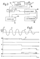
- generator 24 ( Figure 4) comprises a known low-pass, wide-band, so-called pi filter 27 substantially comprising an inductor L1 located in series between two capacitors C1 and C2; filter 27 is supplied by a high-frequency oscillator 29 via an output power amplifier 31; and a regulated, so-called switching, power supply 28 supplies oscillator 29 and the other electronic components of device 23.
- Oscillator 29 is frequency adjustable within certain limits, and may be selected to generate a sinusoidal signal of 400 to 1200 kHz frequency.
- Amplifier 31 is a so-called class A type, provides for linear amplification of the amplitude of the sinusoidal signal, and may advantageously be selected to supply a peak-to-peak signal amplitude of 15 to 20 volts, and preferably of about 18 volts.
- the frequency generated by oscillator 29 must be selected as a function of the physical characteristics of electric spindle 13, 17, i.e. as a function of the in-service parasitic capacitance CP ( Figures 1 and 3) between stator 19 and rotor 18, due to the gap 15 defined by the air-cushion supports.
- capacitance CP normally ranges beteen 10 and 12 picofarads
- oscillator 29 ( Figure 4) may advantageously be selected to generate a signal of about 1000 kHz frequency.
- Filter 27 must be so selected as to be tuned to the output frequency of oscillator 29, and is therefore referred to hereinafter as the tuned filter. Filter 27 therefore transmits the selected output frequency at maximum energy, attenuates or suppresses the other frequencies, in particular the harmonics of the selected frequency, and may advantageously be tuned to a frequency range differing by plus or minus 50 kHz from the selected frequency.
- the output of tuned filter 27 comprises two wires connected to a connector 32, to which may be connected a complementary connector 33 connected to a further two wires 34 and 36.
- Wire 34 is connected electrically to bush 22 ( Figure 1), which is normally made of conducting material and fitted removably to device 21.
- bush 22 is insulated with respect to device 21, e.g. by means of a ring 37 of insulating material, or device 21 may be made entirely of insulating material, e.g. ceramic.
- Wire 36 is connected electrically to stator 19, which in turn is connected to head 11 by a joint 38 insulated electrically from head 11, as described later on.
- stator 19 is grounded by an inductor L, e.g. of about 500 microhenries, which insulates the stator at the operating frequency, but acts as a resistor at mains frequency.
- the capacitance at the output of tuned filter 27 ( Figure 4) therefore normally assumes a first low value when tool 14 is detached from surface 10 of board 6, so that the peak-to-peak amplitude A of the output signal of filter 27 ( Figure 5) is about 18 volts.
- the parasitic capacitance CP between stator 19 and rotor 18 is inserted parallel with capacitance C2 of tuned filter 27. Since capacitance CP is much higher than that in the absence of contact by tool 14, the reactance of filter 27 is reduced, and the peak-to-peak amplitude a of the output signal falls to about 2 volts, well below the above mentioned amplitude A .
- Generator 24 ( Figure 4) also comprises a circuit 39 for rectifying and leveling the incoming signal, and which substantially comprises a diode and a capacitor, and generates a rectified, substantially leveled output signal (see also Figure 5, in which the signals are indicated on the left by the reference numbers of the respective circuits).
- the output signal of circuit 39 is supplied to a comparator 41 for comparison with a threshold signal S.
- Threshold S must be so selected as to permit comparator 41 to pass from a high signal when tool 14 is detached from surface 10, to a low signal when tool 14 contacts surface 10.
- the low signal is stored in memory 25, which substantially comprises a flip-flop set to memorize only the first contact of tool 14 with surface 10, so that, until it is reset, any bounce or subsequent contact has no effect on the state of the flip-flop.
- Enabling circuit 26 normally blocks the digital signals received from a normal Z axis position transducer 42; and, when set, memory 25 conditions circuit 26 to supply the digital signals to unit 16 to feedback control the travel of electric spindle 13, 17.
- a second photocoupler 46 is located between control unit 16 and memory 25; and, at the end of each drilling cycle, unit 16 supplies an end-of-cycle signal to reset memory 25.
- Control device 23 operates as follows.
- unit 16 lowers electric spindle 13, 17 until the tip of tool 14 contacts upper surface 10 of conducting layer 9 of board 6. Since, at this point in time, tuned filter 27 is connected to capacitance C between stator 19 and rotor 18, circuit 41 generates a trailing edge of the respective output signal to set flip-flop 25. Via photocoupler 43, flip-flop 25 conditions circuit 26 to supply the digital signals from transducer 42 to unit 16, which, by feedback control, lowers electric spindle 13, 17 by the number of elementary steps corresponding to the depth K memorized in register 20, arrests the travel of electric spindle 13, 17, and emits an end-of-cycle signal to reset flip-flop 25 via photocoupler 46.
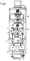
- operating head 11 comprises an aluminium alloy body 48 with a bottom crosspiece 49 comprising a seat in which is fitted an air-cushion bush 51 for creating, in use, a further air-cushion gap 52 (Figure 7).
- Stator 19 is fitted in axially-sliding manner inside bush 51 ( Figure 6) as described in Italian Patent Application TO93A 000831 filed on 5 November, 1993, by the present Applicant.
- Stator 19 comprises two air-cushion supports 53 for supporting rotor 18 by means of radial air cushions; an air-cushion support 54 for supporting rotor 18 by means of an axial air cushion, supports 53 and 54 creating, in use, gap 15 ( Figure 1); a fitting 56 ( Figure 6) for insertion of the electric supply wires and inductor L; and a fitting 57 for connecting wire 36.
- Head 11 also comprises a fixed top crosspiece 58 in turn comprising a central opening 59 housing for rotation the top end of a screw 61.
- Screw 61 engages a nut screw 62 fitted to a movable crosspiece 63 also fitted with two columns 64 sliding inside two bushes on fixed crosspiece 58.
- Head 11 also comprises a top wall 66 fitted with a d.c. electric motor 67 for controlling the travel of electric spindle 13, 17, for which purpose, the shaft of motor 67 is connected to the top end of screw 61 by a further joint 68.
- Movable crosspiece 63 is connected by two pneumatic actuators 69 to two columns 70 fitted with board holder device 21, which substantially comprises a ring 71 fitted removably with bush 22 by means of an electrically conducting washer 65 to which wire 34 is connected.
- Ring 71 comprises two integral arms 72 fitted to the bottom ends of columns 70; and ring 71 and arms 72 may advantageously be made of known 35-70 anodized anticorodal aluminium, which is sufficiently insulating electrically.
- Crosspiece 63 is fitted at the bottom with a bracket 73 engaged by a pin 74 for preventing stator 19 from rotating inside bush 51, and which is fitted to a rod 75 integral with stator 19.
- Joint 38 is connected to crosspiece 63 by a column 76 comprising a bottom threaded seat 77 which is screwed on to a screw 78 of joint 38, and a top threaded seat 79 which is screwed on to a further threaded pin 80 fitted to crosspiece 63.
- both pin 74 and column 76 are made of insulating material, e.g. Delrin (registered trademark).
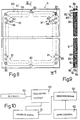
- board 6 ( Figures 8 and 9) may be provided with at least two series 81 of holes, in which each hole extends up to a respective conducting layer 9.
- board 6 comprises four conducting layers 9a, 9b, 9c, 9d alternating with three fiberglass-reinforced plastic layers 7a, 7b, 7c; and each series 81 of holes comprises a hole 82 through layers 9a, 7a up to layer 9b, a hole 83 through the same layers as hole 82 and through layers 9b, 7b up to layer 9c, and a hole 84 through the same layers as hole 83 and through layers 9c, 7c up to layer 9d.
- the respective conducting layer 9b, 9c, 9d comprises a pad 85 connected by a respective conducting track 86, 87, 88 to the two metal pins 89 normally provided on board 6 for positioning it with respect to worktable 12, and which, in use, provide for electrically connecting pads 85 to bush 22 ( Figure 2).
- board 6 is normally four-sided, provision may advantageously be made for four series 81 of holes 82-84, each located adjacent to a respective corner of board 6.
- control unit 16 Prior to the actual drilling cycle, control unit 16 ( Figure 4) is programmed to perform a self-teaching cycle to determine the actual distances between layers 9b-9d and surface 10 of board 6. That is, unit 16 first inserts tool 14 through holes 82-84 to locate and acquire the depth of layers 9b-9d in the four series 81 of holes 82-84; determines the mean thickness of pairs of layers 9a-7a, 9b-7b, 9c-7c and the mean depth of the four corresponding holes 82-84; and memorizes the various mean values in respective registers 20, for use as the depth value K by which to drill the specific board 6.
- Device 23 therefore provides for a machining depth control method comprising a step 90 ( Figure 10) for determining electrical contact between tool 14 and board 6; a step 91 for generating a signal indicating a predetermined capacitance between stator 19 and rotor 18 following contact; a step 92 for memorizing said signal; and a step 93 for controlling the machining depth K at which said signal was generated.
- the board comprises at least one series 81 of holes 82-84
- the method also comprises a self-teaching step 95 to determine depth K by probing holes 82-84.
- machining depth control device 23 As compared with known devices, the advantages of machining depth control device 23 according to the invention will be clear from the foregoing description. In particular, it provides for eliminating errors due to determining the position of the tool with respect to the board holder; for eliminating the complications involved in the manufacture of the proximity sensor and air-cushion piston of known devices; and, finally, by automatically determining the thickness of layers 7, 9 in holes 82-84, for eliminating errors due to varying thicknesses of boards 6, even in the same production lot.
Landscapes
- Engineering & Computer Science (AREA)
- Mechanical Engineering (AREA)
- Manufacturing & Machinery (AREA)
- Microelectronics & Electronic Packaging (AREA)
- Physics & Mathematics (AREA)
- General Physics & Mathematics (AREA)
- Perforating, Stamping-Out Or Severing By Means Other Than Cutting (AREA)
- Drilling And Boring (AREA)
- Supply And Installment Of Electrical Components (AREA)
Applications Claiming Priority (2)
| Application Number | Priority Date | Filing Date | Title |
|---|---|---|---|
| IT96TO000415A IT1285334B1 (it) | 1996-05-17 | 1996-05-17 | Apparecchiatura e relativo metodo di controllo della profondita' di lavorazione per una macchina operatrice per piastre di circuiti |
| ITTO960415 | 1996-05-17 |
Publications (2)
| Publication Number | Publication Date |
|---|---|
| EP0808087A2 true EP0808087A2 (de) | 1997-11-19 |
| EP0808087A3 EP0808087A3 (de) | 1998-09-09 |
Family
ID=11414642
Family Applications (1)
| Application Number | Title | Priority Date | Filing Date |
|---|---|---|---|
| EP97107952A Withdrawn EP0808087A3 (de) | 1996-05-17 | 1997-05-15 | Vorrichtung und Verfahren zur Steuerung der Bearbeitungstiefe einer Maschine zum Bearbeiten von mehrschichtigen Leiterplatten |
Country Status (4)
| Country | Link |
|---|---|
| US (2) | US6015249A (de) |
| EP (1) | EP0808087A3 (de) |
| JP (1) | JPH1058284A (de) |
| IT (1) | IT1285334B1 (de) |
Cited By (6)
| Publication number | Priority date | Publication date | Assignee | Title |
|---|---|---|---|---|
| US6651866B2 (en) | 2001-10-17 | 2003-11-25 | Lilogix, Inc. | Precision bond head for mounting semiconductor chips |
| ITBS20100131A1 (it) * | 2010-07-26 | 2012-01-27 | Cover Technology S R L | Macchina fresatrice |
| CN102883536A (zh) * | 2012-09-29 | 2013-01-16 | 杭州华三通信技术有限公司 | 一种pcb板通孔加工方法及通孔结构 |
| CN103776361A (zh) * | 2014-01-15 | 2014-05-07 | 中钞信用卡产业发展有限公司 | 一种双界面卡内天线的深度检测装置及检测方法 |
| CN103791808A (zh) * | 2014-02-26 | 2014-05-14 | 广州市明森机电设备有限公司 | 一种双界面卡内天线的深度检测装置及检测方法 |
| CN112804825A (zh) * | 2021-04-09 | 2021-05-14 | 苏州维嘉科技股份有限公司 | 控深钻孔的补偿方法和钻孔设备 |
Families Citing this family (30)
| Publication number | Priority date | Publication date | Assignee | Title |
|---|---|---|---|---|
| IT1285334B1 (it) * | 1996-05-17 | 1998-06-03 | Pluritec Italia | Apparecchiatura e relativo metodo di controllo della profondita' di lavorazione per una macchina operatrice per piastre di circuiti |
| FR2774617B1 (fr) * | 1998-02-06 | 2000-05-05 | St Microelectronics Sa | Procede et machine d'usinage d'une cavite dans une carte a puce electronique renfermant une antenne |
| US6199290B1 (en) * | 1999-07-30 | 2001-03-13 | Excellon Automation Co. | Method and apparatus for automatic loading and registration of PCBs |
| CA2434359A1 (en) * | 2001-01-16 | 2002-07-25 | Tyco Electronics Corporation | Circuit board router apparatus and method thereof |
| US6550118B2 (en) * | 2001-02-02 | 2003-04-22 | Electroimpact, Inc. | Apparatus and method for accurate countersinking and rivet shaving for mechanical assembly operations |
| US20030115757A1 (en) * | 2001-10-26 | 2003-06-26 | Claudio Meisser | Method and equipment for stripping a flat cable |
| US6745611B2 (en) * | 2002-02-19 | 2004-06-08 | Fci Americas Technology, Inc. | Battery powered hydraulic tool |
| EP1476273A1 (de) * | 2002-02-22 | 2004-11-17 | Ballado Investments Inc. | Werkstückhaltevorrichtung mit zwei abwechselnd einschaltbaren druckringen |
| ES2287730T3 (es) * | 2003-06-02 | 2007-12-16 | Novator Ab | Procedimiento y aparato para medir la profundidad de agujeros en piezas de trabajo de material compuesto maquinadas por una herramienta de corte orbital. |
| JP4180476B2 (ja) * | 2003-09-09 | 2008-11-12 | 日立ビアメカニクス株式会社 | ワーク押さえを備える主軸装置 |
| WO2005029928A2 (en) * | 2003-09-19 | 2005-03-31 | Viasystems Group, Inc. | Closed loop backdrilling system |
| JP4367854B2 (ja) * | 2004-06-01 | 2009-11-18 | 日立ビアメカニクス株式会社 | プリント基板の穴あけ方法およびプリント基板加工機 |
| US7625158B2 (en) * | 2006-09-22 | 2009-12-01 | Murray Houlton Forlong | Clamping assembly |
| US8047749B2 (en) * | 2007-08-30 | 2011-11-01 | The Boeing Company | Rapid inspection of lightning strike protection systems prior to installing fastener |
| US8668410B1 (en) * | 2009-11-13 | 2014-03-11 | The Boeing Company | Drilling system stabilization |
| WO2011149485A1 (en) * | 2010-05-28 | 2011-12-01 | E. I. Du Pont De Nemours And Company | Process for producing standardized assay areas on organic coatings |
| JP5583555B2 (ja) * | 2010-11-09 | 2014-09-03 | ビアメカニクス株式会社 | 加工装置 |
| US9199351B2 (en) * | 2011-05-09 | 2015-12-01 | The Boeing Company | Drilling machine having hole measurement capability |
| JP6023574B2 (ja) * | 2012-12-10 | 2016-11-09 | ビアメカニクス株式会社 | 基板穴明け装置及び基板穴明け方法 |
| DE102013004679B4 (de) * | 2013-03-19 | 2017-11-23 | Skybrain Vermögensverwaltung GmbH | Vorrichtung und Verfahren zum Bearbeiten von Leiterplatten |
| US9341670B2 (en) | 2014-05-20 | 2016-05-17 | International Business Machines Corporation | Residual material detection in backdrilled stubs |
| US20150359110A1 (en) * | 2014-06-06 | 2015-12-10 | Keysight Technologies, Inc. | Inner layer depth detection during controlled-depth drilling using continuity test coupon |
| EP2987576A1 (de) * | 2014-08-19 | 2016-02-24 | Skybrain Vermögensverwaltungs GmbH | Verfahren zur Herstellung einer Bohrung und Bohrmaschine hierfür |
| US10237983B2 (en) | 2014-12-23 | 2019-03-19 | Sanmina Corporation | Method for forming hole plug |
| CN104764395A (zh) * | 2015-03-27 | 2015-07-08 | 深圳崇达多层线路板有限公司 | 一种印制电路板的切割深度测试方法及电路板 |
| JP6485774B2 (ja) * | 2015-11-11 | 2019-03-20 | 大船企業日本株式会社 | 多層プリント配線基板におけるバックドリル加工方法及び基板加工装置 |
| JP7386034B2 (ja) * | 2018-12-11 | 2023-11-24 | ビアメカニクス株式会社 | ドリル加工装置及びドリル加工方法 |
| WO2021207351A1 (en) | 2020-04-07 | 2021-10-14 | Nextgin Technology Bv | Methods and systems for back-drilling a multi-layer circuit board |
| CN114900966B (zh) * | 2022-05-19 | 2023-09-01 | 深圳崇达多层线路板有限公司 | 电路板近孔背钻方法、电路板、通讯电子设备及加工装置 |
| CN116546727B (zh) * | 2023-05-04 | 2024-06-14 | 江西景旺精密电路有限公司 | 一种增加弯折能力以及控深精度的半刚挠产品控深铣工艺 |
Family Cites Families (13)
| Publication number | Priority date | Publication date | Assignee | Title |
|---|---|---|---|---|
| US3527138A (en) * | 1969-03-24 | 1970-09-08 | Lockheed Aircraft Corp | Apparatus for removing electrical insulation |
| JPS5929383B2 (ja) * | 1975-07-23 | 1984-07-20 | 株式会社日立製作所 | 工作機械における切削工具と被加工物との接触検出装置 |
| JPS5469883A (en) * | 1977-11-14 | 1979-06-05 | Toyoda Mach Works Ltd | Contact detecting device |
| US4451892A (en) * | 1980-01-31 | 1984-05-29 | Mcmurtry David R | Method of and apparatus for measuring distances in numerically controlled machine tools |
| US4765784A (en) * | 1984-12-06 | 1988-08-23 | Advanced Controls, Inc. | Electronic depth control for drill |
| JPS61214953A (ja) * | 1985-03-15 | 1986-09-24 | Dai Showa Seiki Kk | 工具とワ−クの接触検知装置 |
| SE463857B (sv) * | 1985-04-01 | 1991-02-04 | Industriverktyg Ab | Indikeringsanordning |
| US4869626A (en) * | 1986-04-18 | 1989-09-26 | Dynamotion Corporation | High speed drilling spindle |
| US5123789A (en) * | 1989-02-28 | 1992-06-23 | Hitachi Seiko, Ltd. | Method of and apparatus for machining printed circuit board |
| US5139376A (en) * | 1991-10-23 | 1992-08-18 | Excellon Automation | Method and apparatus for controlled penetration drilling |
| JP3404771B2 (ja) * | 1992-09-24 | 2003-05-12 | 株式会社デンソー | 多層配線基板加工装置及び加工方法 |
| DE4340249A1 (de) * | 1993-11-26 | 1995-06-01 | Schmoll Gmbh Maschinen | Vorrichtung zum Tiefenbohren von Leiterplatten o. dgl. |
| IT1285334B1 (it) * | 1996-05-17 | 1998-06-03 | Pluritec Italia | Apparecchiatura e relativo metodo di controllo della profondita' di lavorazione per una macchina operatrice per piastre di circuiti |
-
1996
- 1996-05-17 IT IT96TO000415A patent/IT1285334B1/it active IP Right Grant
-
1997
- 1997-05-15 EP EP97107952A patent/EP0808087A3/de not_active Withdrawn
- 1997-05-15 US US08/856,793 patent/US6015249A/en not_active Expired - Fee Related
- 1997-05-16 JP JP9127034A patent/JPH1058284A/ja active Pending
-
1999
- 1999-10-19 US US09/572,916 patent/US6309151B1/en not_active Expired - Fee Related
Cited By (9)
| Publication number | Priority date | Publication date | Assignee | Title |
|---|---|---|---|---|
| US6651866B2 (en) | 2001-10-17 | 2003-11-25 | Lilogix, Inc. | Precision bond head for mounting semiconductor chips |
| WO2003034472A3 (en) * | 2001-10-17 | 2003-12-11 | Lilogix Inc Doing Business As | Precision bond head for mounting semiconductor chips |
| ITBS20100131A1 (it) * | 2010-07-26 | 2012-01-27 | Cover Technology S R L | Macchina fresatrice |
| CN102883536A (zh) * | 2012-09-29 | 2013-01-16 | 杭州华三通信技术有限公司 | 一种pcb板通孔加工方法及通孔结构 |
| CN102883536B (zh) * | 2012-09-29 | 2015-12-02 | 杭州华三通信技术有限公司 | 一种pcb板通孔加工方法及通孔结构 |
| CN103776361A (zh) * | 2014-01-15 | 2014-05-07 | 中钞信用卡产业发展有限公司 | 一种双界面卡内天线的深度检测装置及检测方法 |
| CN103791808A (zh) * | 2014-02-26 | 2014-05-14 | 广州市明森机电设备有限公司 | 一种双界面卡内天线的深度检测装置及检测方法 |
| CN103791808B (zh) * | 2014-02-26 | 2017-02-15 | 广州明森科技股份有限公司 | 一种双界面卡内天线的深度检测装置及检测方法 |
| CN112804825A (zh) * | 2021-04-09 | 2021-05-14 | 苏州维嘉科技股份有限公司 | 控深钻孔的补偿方法和钻孔设备 |
Also Published As
| Publication number | Publication date |
|---|---|
| EP0808087A3 (de) | 1998-09-09 |
| ITTO960415A1 (it) | 1997-11-17 |
| US6015249A (en) | 2000-01-18 |
| US6309151B1 (en) | 2001-10-30 |
| ITTO960415A0 (it) | 1996-05-17 |
| JPH1058284A (ja) | 1998-03-03 |
| IT1285334B1 (it) | 1998-06-03 |
Similar Documents
| Publication | Publication Date | Title |
|---|---|---|
| US6015249A (en) | Device and method for controlling the machining depth of a machine for machining multilayer printed circuit boards | |
| US7426876B2 (en) | Machine tool | |
| US5123789A (en) | Method of and apparatus for machining printed circuit board | |
| US4765784A (en) | Electronic depth control for drill | |
| JP2007509487A (ja) | 閉ループ・バックドリル加工システム | |
| KR20190065540A (ko) | 백 드릴 가공장치 및 백 드릴 가공방법 | |
| CN113347792A (zh) | 基板加工装置和其转轴下降距离信息检测机构 | |
| TWI825238B (zh) | 鑽孔加工裝置及鑽孔加工方法 | |
| KR101775589B1 (ko) | 가공 장치 | |
| JP2005116945A (ja) | 多層プリント配線板、そのスタブ座ぐり装置、方法 | |
| JPH0518791A (ja) | 非接触距離計測用センサ装置 | |
| JP4614337B2 (ja) | 工具の先端位置検出方法、ワークの加工方法および摩耗状態検出方法 | |
| JP2003001548A (ja) | 止まり穴加工方法およびワークの検査方法 | |
| CN115255467A (zh) | 一种控深加工系统和方法 | |
| CN109304640A (zh) | 一种接触反馈式测量装置以及数控机床 | |
| JP5453640B2 (ja) | 放電加工機 | |
| JP2016223861A (ja) | スピンドル下降距離情報検出機構及びスピンドル下降距離情報検出機構を組み込んだ基板加工装置 | |
| JP4557792B2 (ja) | 距離測定装置及び工作機械 | |
| JP2559788B2 (ja) | プリント基板の加工装置 | |
| JPH0360906A (ja) | ワーク上面を基準とする加工方法およびその装置 | |
| JPH05337895A (ja) | プリント基板穴明機 | |
| JP4072377B2 (ja) | 工具状態検知装置 | |
| TW544354B (en) | Method for determining uncertainties for printed circuit board drilling machines | |
| JP2003025083A (ja) | レーザ加工装置およびその動作制御方法 | |
| JP4824515B2 (ja) | 工具の位置検出方法およびプリント基板加工装置 |
Legal Events
| Date | Code | Title | Description |
|---|---|---|---|
| PUAI | Public reference made under article 153(3) epc to a published international application that has entered the european phase |
Free format text: ORIGINAL CODE: 0009012 |
|
| AK | Designated contracting states |
Kind code of ref document: A2 Designated state(s): BE CH DE FR GB LI |
|
| PUAL | Search report despatched |
Free format text: ORIGINAL CODE: 0009013 |
|
| AK | Designated contracting states |
Kind code of ref document: A3 Designated state(s): BE CH DE FR GB LI |
|
| 17P | Request for examination filed |
Effective date: 19981118 |
|
| RAP1 | Party data changed (applicant data changed or rights of an application transferred) |
Owner name: ACD TECHNOLOGIES S.P.A |
|
| 17Q | First examination report despatched |
Effective date: 20070525 |
|
| STAA | Information on the status of an ep patent application or granted ep patent |
Free format text: STATUS: THE APPLICATION IS DEEMED TO BE WITHDRAWN |
|
| 18D | Application deemed to be withdrawn |
Effective date: 20081202 |