EP0809339A1 - Appareil pour installation électrique - Google Patents
Appareil pour installation électrique Download PDFInfo
- Publication number
- EP0809339A1 EP0809339A1 EP97890080A EP97890080A EP0809339A1 EP 0809339 A1 EP0809339 A1 EP 0809339A1 EP 97890080 A EP97890080 A EP 97890080A EP 97890080 A EP97890080 A EP 97890080A EP 0809339 A1 EP0809339 A1 EP 0809339A1
- Authority
- EP
- European Patent Office
- Prior art keywords
- fixing body
- installation device
- recess
- electrical installation
- adjusting element
- Prior art date
- Legal status (The legal status is an assumption and is not a legal conclusion. Google has not performed a legal analysis and makes no representation as to the accuracy of the status listed.)
- Granted
Links
- 238000010616 electrical installation Methods 0.000 title claims description 22
- 238000009434 installation Methods 0.000 claims description 71
- 239000000463 material Substances 0.000 claims description 9
- 230000008719 thickening Effects 0.000 claims description 9
- 238000006073 displacement reaction Methods 0.000 claims description 7
- 239000002184 metal Substances 0.000 claims description 5
- 239000012777 electrically insulating material Substances 0.000 claims description 2
- 210000000078 claw Anatomy 0.000 description 23
- 238000013461 design Methods 0.000 description 8
- 239000012791 sliding layer Substances 0.000 description 3
- 230000007480 spreading Effects 0.000 description 3
- 230000002349 favourable effect Effects 0.000 description 2
- 230000004048 modification Effects 0.000 description 2
- 238000012986 modification Methods 0.000 description 2
- DHKHKXVYLBGOIT-UHFFFAOYSA-N 1,1-Diethoxyethane Chemical compound CCOC(C)OCC DHKHKXVYLBGOIT-UHFFFAOYSA-N 0.000 description 1
- 239000011354 acetal resin Substances 0.000 description 1
- 230000001154 acute effect Effects 0.000 description 1
- 230000005540 biological transmission Effects 0.000 description 1
- 230000015572 biosynthetic process Effects 0.000 description 1
- 239000000919 ceramic Substances 0.000 description 1
- 229910010293 ceramic material Inorganic materials 0.000 description 1
- 239000011248 coating agent Substances 0.000 description 1
- 238000000576 coating method Methods 0.000 description 1
- 230000006835 compression Effects 0.000 description 1
- 238000007906 compression Methods 0.000 description 1
- 238000010276 construction Methods 0.000 description 1
- 239000002783 friction material Substances 0.000 description 1
- 238000003780 insertion Methods 0.000 description 1
- 230000037431 insertion Effects 0.000 description 1
- 229920006324 polyoxymethylene Polymers 0.000 description 1
- 230000009467 reduction Effects 0.000 description 1
- 238000012549 training Methods 0.000 description 1
- 230000007704 transition Effects 0.000 description 1
- 238000013519 translation Methods 0.000 description 1
Images

Classifications
-
- H—ELECTRICITY
- H02—GENERATION; CONVERSION OR DISTRIBUTION OF ELECTRIC POWER
- H02G—INSTALLATION OF ELECTRIC CABLES OR LINES, OR OF COMBINED OPTICAL AND ELECTRIC CABLES OR LINES
- H02G3/00—Installations of electric cables or lines or protective tubing therefor in or on buildings, equivalent structures or vehicles
- H02G3/02—Details
- H02G3/08—Distribution boxes; Connection or junction boxes
- H02G3/18—Distribution boxes; Connection or junction boxes providing line outlets
Definitions
- the invention relates to an electrical installation device with a base body and at least one movably arranged on this fixing body, which is provided for holding the installation device in an installation box and with the help of an adjusting element can be moved from an inner rest position to the outside into an operating position and with its outside to the inside surface the installation box can be pressed, and which can be moved from this operating position back into the rest position and can thus be detached from the inner surface of the installation box.
- An installation device is known from DE 18 39 475 U, in which a fixing body is provided with a wedge surface that slides on an inclined edge of a base base body.
- a clamping screw serves as an adjusting element in order to press the fixing body outwards along the inclined surface of the rim when the clamping screw is screwed into the fixing body.
- This construction has the disadvantage that the clamping screw is inevitably inclined when screwed in, as a result of which it can rub in the threaded bore in the fixing body and can only be released with difficulty if the fixing body is to be reset. Above all, however, the fixing body is then inclined with the screw so that it can no longer slide with its wedge surface on the inclined edge, but will "eat” firmly with an edge and edge.
- DE 21 40 397 A shows an installation device with two molded on the base, i.e. with it one-piece spreading levers which can be pivoted radially outwards by means of a wedge body adjustable via a set screw or by a set screw pressing on a wedge surface, the pivot point of the pivoting movement being fixed by a film hinge or by the transition of the spreading lever to the base. There, however, it can easily tear or break.
- the aim is also to achieve an exact adjustment and return of the fixing bodies as well as permanent training.
- the electrical installation device is characterized in that the slide-like fixing body in a in the base body provided recess is generally radially displaceable.
- the above objective is met in an advantageous manner, with in particular an exact movement of the respective fixing body being ensured when the installation device is fixed in an installation box by the fixing body in the associated recess in the base body being generally radially outward, i.e. in the direction of the Center axis of the base body towards the can wall is moved.
- the fixing body can be provided on its radially outer end face or outside with claw elements or the like, with which it ensures a firm hold on the inner surface of the installation box when it is moved outward.
- claw elements can be present in different depth positions on the fixing body, based on the axial direction of the installation device, the fixing body itself having a relatively large axial dimension, at least on its radial outside, so that the fixing body also has claw elements in the area of cable lead-through openings in the installation box the can wall, namely in particular between these openings and in the assembled state with the wall in which the installation box is inserted, the front side of the installation box (or away from the front axially behind these openings).
- a pin-like adjusting element which is rotatably mounted on the base body is provided, this can interact in various ways with the slidingly displaceable fixing body, in extreme cases even via a gearwheel attached to the adjusting element, optionally - for the purpose of reduction - an intermediate gearwheel and one provided on the side of the fixing body Rack.
- the pin-like adjusting element is rotatably arranged on the base body and the fixing body is arranged in the direction of its displacement has an obliquely extending wedge surface, the adjusting element which is axially adjustable when rotating with respect to the base body rests on the wedge surface of the fixing body.
- the adjusting element thus carries a screw thread in a manner known per se, with which it is axially adjustable with respect to the base body, and the fixing body forms a type of wedge, on the inclined wedge surface of which the adjusting element rests and, in the event of an adjustment, exerts a force which exerts it Wedge surface is broken down into components, one of which is used to move the fixing body radially outward.
- the system wedge-surface-adjusting element thread is self-locking, so that the fixing body can be pressed with sufficient force against the inner surface of the installation box to prevent undesired pulling out of the installation device from the box.
- the fixing body is provided with a groove-like recess into which the pin-like adjusting element protrudes, where it is in positive engagement with a wall of this recess.
- the groove-like recess provided in the fixing body forms the wedge surface and has undercut-shaped side walls, the geometric axis of this recess being in the radial plane corresponding to the displaceability of the fixing body and obliquely to the geometric axis of the sliding position of the fixing body, and that pin-like adjusting element has a thickening located in the groove-like recess of the fixing body, which is held in a form-fitting manner in the groove-like recess in the axial direction of the adjusting element and is displaceable in this recess in the axial direction of the groove-like recess.
- the greatest possible wedge angle of the wedge surface (relative to the direction of the sliding movement) would be favorable for the force transmission during the radial adjustment of the fixing body; for the self-locking described, on the other hand, however, the wedge angle of the wedge, based on the direction of the displacement movement of the fixing body, should be selected to be comparatively small.
- the inclined position of the wedge surface with respect to the geometrical axis of the displacement of the fixing body is between 20 ° and 45 °, it being particularly preferred that the inclined position is approximately 30 °.
- the fixing body can be moved radially and at least by spring force into the outer operating position can be fixed in the operating position.
- the fixing body can consist of metal, which has claws on the outside.
- the respective fixing body extends relatively far radially inwards compared to an installation device with the known expanding claws within the base body, and it can get close to electrical connection parts, it has also proven to be advantageous for safety reasons if the Fixing body made of electrically insulating material.
- the fixing body can be made of, for example Plastic or ceramic consist, whereas the base body of the installation device can consist of an acetal resin, for example. With materials of this type, good sliding ability of the fixing body in the base body is also ensured.
- the fixing body can be provided on its radial outside (end face), for example, with strip-shaped claw elements; preferably it has one or more serrations or spikes on the outside.
- These prongs or spikes could be formed from the material of the fixing body, but it is then necessary that the material of the fixing body has sufficient hardness.
- Such a formation of prongs, strips or thorns directly and simply from the material of the fixing body would be conceivable above all if corrugation or the like is provided on the inner surface of the installation box, as is known per se; a kind of positive engagement of the inner surface of the can and the fixing body would then be obtained.
- the prongs or spikes provided on the outside of the fixing body are located closer to the front of the installation device Zone of the fixing body is arranged or are.
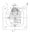
- a base body 2 is provided in a conventional manner, which in the present example is designed for the realization of a Schuko socket and is also connected in a conventional manner to a frame 3, which defines the front 3 'of the installation device 1 in the installed state (see FIG. 2).
- the frame 3 is fastened to the base body 2 by means of rivet sleeves 5 with tabs 4 angled backwards, and these rivet sleeves 5 are provided with an internal thread, each with a pin-like adjusting element 6, which has a shaft section 7 having a corresponding external thread, is screwed into these threaded rivet sleeves 5.
- a recess 9 is provided, in which a fixing body 10 is slidably received.
- This fixing body 10 is designed in the manner of a slide and can be adjusted in translation, with its inside or underside sliding on the bottom 11 of the recess 9.
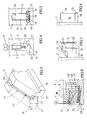
- the fixing body 10 is, as can be seen from FIG. 2 in particular also from FIG. 3, designed overall in the manner of a wedge, its top side facing the front 3 'of the installation device 1 having a wedge surface 12 which is connected to the pin-like adjusting element 6 , namely with its inner end face, which in the present example has a generally lenticular thickening 13, cooperates.
- the or each fixing body 10 On its radially outer end face, hereinafter referred to briefly as the outer face, the or each fixing body 10 carries a claw element with which it is in the operating position, cf. Fig.2, right half, is pressed against the inner surface 14 of an installation box 15, which is provided for receiving the installation device 1.
- this claw element is formed by mandrels 16, preferably two such mandrels 16 each being provided next to one another on the outside of the fixing body 10 (as can be seen from FIG. 1, in which these mandrels 16 were drawn in for the purpose of illustration, even if they would not be visible according to the cut II in Figure 2).
- the mandrels 16 are through the tips of metal pins 17 embedded in the material of the fixing bodies 10 are formed.
- the material of the respective fixing body 10 is preferably an insulating plastic or ceramic material, but possibly also metal.
- the or each fixing body 10 has lateral guide flanges 18, 19 in its base area, with which it fits into corresponding lateral recesses 20, 21 of the recess 9 in the base body 2 (cf. also FIGS. 4 and 5) is performed.
- the fixing body 10 On its wedge surface top, the fixing body 10 has a groove-like recess 22, the side walls of which are undercut, so that a wider guide "chamber” 23 is obtained below or inside an inner guide slot 24, the bottom 12 'of which forms the wedge surface 12 mentioned above.
- This wedge surface 12 extends at an angle ⁇ (see FIG. 7) relative to the geometrical axis 25 (see FIG. 2, left half) of the sliding mounting of the fixing body 10 in the recess 9, and that it rises radially outward from the inside, this wedge angle ⁇ for example 30 °, generally between 20 ° and 45 °.
- the fixing body 10 has broken out in the region of the two ends 26, 27 of its groove-like recess 22 in order to insert the adjusting element 6 with its lenticular thickening 13 into the elongated chamber 23 of the groove-like at these ends 26, 27 To be able to insert recess 22.
- the lenticular thickening 13, as can be seen in particular from FIG. 4, is connected via a shaft section 28 with a smaller cross section to the threaded section 7 of the adjusting element 6, which carries the external thread.
- This shaft section 28 with a smaller cross section slides in operation in the narrower guide slot 24, and the undercut design of the side walls of the groove-like recess 22 in connection with the lenticular thickening 13 of the adjusting element 6 ensures that the adjusting element 6 when turning or axially adjusting (screwing in or unscrewing) in the base body 2, both an outward displacement of the fixing body 10 (by attacking the wedge surface 12) and an inward pushing (by attacking the top of the thickening 13 on the undercuts) is made possible.
- each fixing body 10 is made of its own inner, in the left half shown in Fig.2 shifted outward against the inner surface 14 of the installation box 15 that the pin-like adjusting element 6 with the help of a suitable tool, such as a screwdriver or an Allen key, depending on the design of the adjusting element 6, rotates and thereby in the sleeve 5 is screwed inward, ie is adjusted axially inward, the end face of the adjusting element 6 with the lenticular thickening 13 being pressed against the wedge surface 12 of the groove-like recess 22.
- a suitable tool such as a screwdriver or an Allen key
- fixing body 10 with wedge surface 12 / adjusting element 6 with external thread / rivet sleeve 5 with internal thread is sufficiently self-locking even in this pressing state, so that the fixing body 10 remains in the fixing position reached, without additional securing elements, such as a counter nut, for the Adjustment element 6 would be required.
- each adjusting element 6 is unscrewed from the inwardly screwed position shown on the right in FIG. 2, its thickening 13 pointing to the upper side as shown in the drawing, FIG the underside of the projecting ledges of the undercut side walls of the groove-like recess 22 comes into contact and so the fixing body 10 again moves from its outer operating position according to FIG. 2, right half, to its inner rest position according to FIG. 2 via the wedge surface defined by these underside of the ledge , left half, withdraws.
- a forced return of the fixing body 10 is thus also realized in a simple manner.
- a modification is provided compared to that according to FIGS. 1 to 3 insofar as here instead of the or preferably in addition to the thorns 16 shown in dashed lines, a lower (in the installed position according to FIG. 2) toothed strip, with pyramid-shaped tips or prongs 29 in a row at the height of the strip-shaped side flanges 18, 19, is provided as a claw element.
- the fixing body 10 ' has a toothing 31 on its outside essentially over its entire height. Furthermore, the fixing body 10 is provided on its oblique wedge surface 12 with a support 32 made of hard, low-friction material; Furthermore, the groove-like recess 22 described above is missing here, so that a simple threaded pin-like adjusting element 6 ', as shown in FIG. 8, can work together with the fixing body 10' in order to adjust it radially outward into the operating position according to FIG.
- a spring 33 (see FIG. 8), such as a tension spring, which acts between the base body 2 and the fixing body 10 and the fixing body 10, can be provided for returning the fixing body 10 ′ to the inner rest position, for example according to FIG. 8 'retracts into the interior of the recess 9.
- the geometrical axis 25 'of the sliding bearing of the fixing body 10' can also slope downwards from the outside inwards, i.e. can include an acute angle with a plane perpendicular to the axis 8 of the installation device 1 - which is parallel to the plane 3 'of the front of the installation device 1, see also FIG. 2.
- FIG. 8 Another modification in the embodiment according to FIG. 8 is that the fixing body 10 'is provided on its side facing the bottom 11 of the groove-like recess 9 with a low-friction sliding layer 34, which is precisely the case with This exemplary embodiment is particularly advantageous, since when the fixing body 10 'is moved outward, a slope - albeit a slight one - has to be overcome (in practice the slope of the geometric axis 25' is a few degrees).
- such a low-friction sliding layer 34 could also form the bottom 11 of the groove-like recess 9 in the base body 2, and such sliding layers can also be arranged in the previously described exemplary embodiments.
- FIG. 7 but also those according to FIGS. 5 and 6, are particularly suitable for working together with installation boxes 15 with corrugations 35 (see FIG. 7) on the inner surface 14, in order to fix the installation device 1 in a particularly good manner To achieve installation box 15.
- the mandrels 16 in the position shown enable a secure hold in the installation box 15 even if there are openings 36 in this box 15 for the passage of electrical leads or cables 37: As can be seen from FIG. 2, it is possible to to provide the mandrels 16 at such a height on the radial outside of the fixing body 10 that they are pressed against the inner surface 14 of the installation box 15 in the region between the opening 36 and the front 3 'of the installation device 1 (which is not possible with the conventional expanding claws) ).
- the radial outside of the fixing bodies 10 and 10 ' is flat in the exemplary embodiments shown, cf. e.g. 1 to 3.
- FIG. 8 an alternative embodiment can be seen from FIG. 8, according to which the — for example block-shaped — fixing body 10 ′′ is adjusted radially outward not with the aid of the screw adjusting element 6 ′ but with the aid of the spring 33 designed as a compression spring.
- the screw 6 ' acts here as a holding element or clamping element, where, as shown in dashed lines in FIG. 8, the block-shaped fixing body 10 ′′ has depressions 38 on its upper side, into which the screw 6 ′ can optionally engage in order to tighten the fixing body 10 ′ in different extension positions.
- FIG. 8 the block-shaped fixing body 10 ′′ has depressions 38 on its upper side, into which the screw 6 ′ can optionally engage in order to tighten the fixing body 10 ′ in different extension positions.
- the fixing body 10 can also have a bevel 39 on its outside on the side facing the base 11, which facilitates the insertion of the base body 2 into the socket 15 when the fixing body 10" protrudes outwards (which then is moved inwards from the edge of the can via this bevel 38).
Landscapes
- Engineering & Computer Science (AREA)
- Architecture (AREA)
- Civil Engineering (AREA)
- Structural Engineering (AREA)
- Connection Of Plates (AREA)
Applications Claiming Priority (3)
| Application Number | Priority Date | Filing Date | Title |
|---|---|---|---|
| AT89796 | 1996-05-21 | ||
| AT897/96 | 1996-05-21 | ||
| AT0089796A AT403637B (de) | 1996-05-21 | 1996-05-21 | Elektrisches installationsgerät |
Publications (2)
| Publication Number | Publication Date |
|---|---|
| EP0809339A1 true EP0809339A1 (fr) | 1997-11-26 |
| EP0809339B1 EP0809339B1 (fr) | 2001-10-24 |
Family
ID=3502349
Family Applications (1)
| Application Number | Title | Priority Date | Filing Date |
|---|---|---|---|
| EP97890080A Expired - Lifetime EP0809339B1 (fr) | 1996-05-21 | 1997-04-30 | Appareil pour installation électrique |
Country Status (4)
| Country | Link |
|---|---|
| EP (1) | EP0809339B1 (fr) |
| AT (1) | AT403637B (fr) |
| DE (1) | DE59705031D1 (fr) |
| HU (1) | HU215425B (fr) |
Cited By (1)
| Publication number | Priority date | Publication date | Assignee | Title |
|---|---|---|---|---|
| EP2315327A3 (fr) * | 2009-10-23 | 2012-03-28 | Abb Ag | Appareil d'installation électrique encastrée doté d'écarteurs |
Citations (4)
| Publication number | Priority date | Publication date | Assignee | Title |
|---|---|---|---|---|
| US4071158A (en) * | 1975-08-11 | 1978-01-31 | Maheu Joseph S | Screw fastening device |
| GB2170660A (en) * | 1985-02-05 | 1986-08-06 | City Electrical Factors Ltd | Wall box for an electrical accessory |
| JPH01270709A (ja) * | 1988-04-23 | 1989-10-30 | Matsushita Electric Works Ltd | 床配線装置 |
| DE3941613A1 (de) * | 1988-12-20 | 1990-06-21 | May & Steffens Gmbh & Co Kg | Befestigungsvorrichtung |
Family Cites Families (3)
| Publication number | Priority date | Publication date | Assignee | Title |
|---|---|---|---|---|
| DE1839475U (de) * | 1961-06-05 | 1961-10-19 | Fritz Keune | Elektroinstallationsgeraet fuer unterputzverlegung bzw. unterputz-schalter oder -steckdose. |
| DE2140397A1 (de) * | 1971-08-12 | 1973-02-15 | Bbc Brown Boveri & Cie | Elektrisches unterputz-installationsgeraet |
| DE4324633C2 (de) * | 1993-07-22 | 2001-05-17 | Abb Patent Gmbh | Elektrisches Installationsgerät |
-
1996
- 1996-05-21 AT AT0089796A patent/AT403637B/de not_active IP Right Cessation
-
1997
- 1997-04-30 EP EP97890080A patent/EP0809339B1/fr not_active Expired - Lifetime
- 1997-04-30 DE DE59705031T patent/DE59705031D1/de not_active Expired - Fee Related
- 1997-05-05 HU HU9700844A patent/HU215425B/hu not_active IP Right Cessation
Patent Citations (4)
| Publication number | Priority date | Publication date | Assignee | Title |
|---|---|---|---|---|
| US4071158A (en) * | 1975-08-11 | 1978-01-31 | Maheu Joseph S | Screw fastening device |
| GB2170660A (en) * | 1985-02-05 | 1986-08-06 | City Electrical Factors Ltd | Wall box for an electrical accessory |
| JPH01270709A (ja) * | 1988-04-23 | 1989-10-30 | Matsushita Electric Works Ltd | 床配線装置 |
| DE3941613A1 (de) * | 1988-12-20 | 1990-06-21 | May & Steffens Gmbh & Co Kg | Befestigungsvorrichtung |
Non-Patent Citations (1)
| Title |
|---|
| PATENT ABSTRACTS OF JAPAN vol. 14, no. 38 (E - 878) 24 January 1990 (1990-01-24) * |
Cited By (2)
| Publication number | Priority date | Publication date | Assignee | Title |
|---|---|---|---|---|
| EP2315327A3 (fr) * | 2009-10-23 | 2012-03-28 | Abb Ag | Appareil d'installation électrique encastrée doté d'écarteurs |
| RU2540120C2 (ru) * | 2009-10-23 | 2015-02-10 | Абб Аг | Электрическое инсталляционное устройство для скрытой проводки с распорками |
Also Published As
| Publication number | Publication date |
|---|---|
| EP0809339B1 (fr) | 2001-10-24 |
| ATA89796A (de) | 1997-08-15 |
| HUP9700844A3 (en) | 1998-05-28 |
| HU9700844D0 (en) | 1997-06-30 |
| HU215425B (hu) | 1998-12-28 |
| DE59705031D1 (de) | 2001-11-29 |
| AT403637B (de) | 1998-04-27 |
| HUP9700844A2 (en) | 1997-12-29 |
Similar Documents
| Publication | Publication Date | Title |
|---|---|---|
| EP3099946B1 (fr) | Moyen d'assemblage et procédé permettant d'assembler deux pièces | |
| AT515425B1 (de) | Vorrichtung zur befestigung einer frontblende an einer seitenzarge eines beweglichen möbelteils eines möbels, schubkasten und möbel | |
| EP3122981B1 (fr) | Dispositif d'étanchéité et moyen pour fixation | |
| DE202014010633U1 (de) | Verbindungsmittel zum Verbinden zweier Bauteile | |
| DE102016121074B3 (de) | Sammelschienenhalter und eine entsprechende Anordnung | |
| EP3356629B1 (fr) | Ferrure pour porte coulissante et procédé de montage d'une porte coulissante | |
| EP0754827A2 (fr) | Dispositif pour la fixation amovible et axialement non coulissante d'une poignée sur un élément de palier, notamment pour une poignée de porte ou fenêtre | |
| WO2012130359A1 (fr) | Système de ferme-porte | |
| AT403637B (de) | Elektrisches installationsgerät | |
| EP4019819B1 (fr) | Dispositif à deux composants, en particulier collier doté d'un anneau de collier | |
| EP3166444A1 (fr) | Guidage télescopique pour une partie de meuble mobile | |
| EP0791759A1 (fr) | Boulon à connexion rapide | |
| WO2022029124A1 (fr) | Dispositif de fixation, procédé, agencement et armoire de distribution | |
| EP0464373B1 (fr) | Elément de connection | |
| EP2690729A1 (fr) | Système d'installation électrique et boîtier pour cloison creuse pour l'installation électrique | |
| EP0843061B1 (fr) | Ferrure pour fenêtre | |
| AT504131B1 (de) | Beschlag | |
| EP3269903A1 (fr) | Garniture à rosette pour poussoir de portes ou de fenêtres | |
| DE29620345U1 (de) | Band für Türen, Fenstern u.dgl. | |
| DE19842409A1 (de) | Elektrisches Installationsgerät | |
| DE9007305U1 (de) | Elektrische Hohlwanddose | |
| DE7114992U (de) | Verschlußvorrichtung fur Möbel | |
| DE20003033U1 (de) | Plattenhalterung und Duschabtrennung | |
| DE4020178A1 (de) | Verbindungselement | |
| DE29921368U1 (de) | Türfutter mit einer Vorrichtung zu seiner Befestigung |
Legal Events
| Date | Code | Title | Description |
|---|---|---|---|
| PUAI | Public reference made under article 153(3) epc to a published international application that has entered the european phase |
Free format text: ORIGINAL CODE: 0009012 |
|
| AK | Designated contracting states |
Kind code of ref document: A1 Designated state(s): BE CH DE ES FR GB GR IT LI PT |
|
| 17P | Request for examination filed |
Effective date: 19971021 |
|
| 17Q | First examination report despatched |
Effective date: 20000508 |
|
| GRAG | Despatch of communication of intention to grant |
Free format text: ORIGINAL CODE: EPIDOS AGRA |
|
| GRAG | Despatch of communication of intention to grant |
Free format text: ORIGINAL CODE: EPIDOS AGRA |
|
| GRAH | Despatch of communication of intention to grant a patent |
Free format text: ORIGINAL CODE: EPIDOS IGRA |
|
| RAP1 | Party data changed (applicant data changed or rights of an application transferred) |
Owner name: LEGRAND OESTERREICH GES.M.B.H. |
|
| GRAH | Despatch of communication of intention to grant a patent |
Free format text: ORIGINAL CODE: EPIDOS IGRA |
|
| GRAA | (expected) grant |
Free format text: ORIGINAL CODE: 0009210 |
|
| AK | Designated contracting states |
Kind code of ref document: B1 Designated state(s): BE CH DE ES FR GB GR IT LI PT |
|
| PG25 | Lapsed in a contracting state [announced via postgrant information from national office to epo] |
Ref country code: IT Free format text: LAPSE BECAUSE OF FAILURE TO SUBMIT A TRANSLATION OF THE DESCRIPTION OR TO PAY THE FEE WITHIN THE PRE;WARNING: LAPSES OF ITALIAN PATENTS WITH EFFECTIVE DATE BEFORE 2007 MAY HAVE OCCURRED AT ANY TIME BEFORE 2007. THE CORRECT EFFECTIVE DATE MAY BE DIFFERENT FROM THE ONE RECORDED.SCRIBED TIME-LIMIT Effective date: 20011024 Ref country code: GB Free format text: LAPSE BECAUSE OF FAILURE TO SUBMIT A TRANSLATION OF THE DESCRIPTION OR TO PAY THE FEE WITHIN THE PRESCRIBED TIME-LIMIT Effective date: 20011024 |
|
| REG | Reference to a national code |
Ref country code: CH Ref legal event code: EP |
|
| REF | Corresponds to: |
Ref document number: 59705031 Country of ref document: DE Date of ref document: 20011129 |
|
| PG25 | Lapsed in a contracting state [announced via postgrant information from national office to epo] |
Ref country code: PT Free format text: LAPSE BECAUSE OF FAILURE TO SUBMIT A TRANSLATION OF THE DESCRIPTION OR TO PAY THE FEE WITHIN THE PRESCRIBED TIME-LIMIT Effective date: 20020124 |
|
| PG25 | Lapsed in a contracting state [announced via postgrant information from national office to epo] |
Ref country code: GR Free format text: LAPSE BECAUSE OF FAILURE TO SUBMIT A TRANSLATION OF THE DESCRIPTION OR TO PAY THE FEE WITHIN THE PRESCRIBED TIME-LIMIT Effective date: 20020125 |
|
| ET | Fr: translation filed | ||
| GBV | Gb: ep patent (uk) treated as always having been void in accordance with gb section 77(7)/1977 [no translation filed] |
Effective date: 20011024 |
|
| PG25 | Lapsed in a contracting state [announced via postgrant information from national office to epo] |
Ref country code: LI Free format text: LAPSE BECAUSE OF NON-PAYMENT OF DUE FEES Effective date: 20020430 Ref country code: ES Free format text: LAPSE BECAUSE OF FAILURE TO SUBMIT A TRANSLATION OF THE DESCRIPTION OR TO PAY THE FEE WITHIN THE PRESCRIBED TIME-LIMIT Effective date: 20020430 Ref country code: CH Free format text: LAPSE BECAUSE OF NON-PAYMENT OF DUE FEES Effective date: 20020430 Ref country code: BE Free format text: LAPSE BECAUSE OF NON-PAYMENT OF DUE FEES Effective date: 20020430 |
|
| PLBE | No opposition filed within time limit |
Free format text: ORIGINAL CODE: 0009261 |
|
| STAA | Information on the status of an ep patent application or granted ep patent |
Free format text: STATUS: NO OPPOSITION FILED WITHIN TIME LIMIT |
|
| 26N | No opposition filed | ||
| REG | Reference to a national code |
Ref country code: CH Ref legal event code: PL |
|
| PGFP | Annual fee paid to national office [announced via postgrant information from national office to epo] |
Ref country code: FR Payment date: 20060428 Year of fee payment: 10 |
|
| PGFP | Annual fee paid to national office [announced via postgrant information from national office to epo] |
Ref country code: DE Payment date: 20070410 Year of fee payment: 11 |
|
| PG25 | Lapsed in a contracting state [announced via postgrant information from national office to epo] |
Ref country code: FR Free format text: LAPSE BECAUSE OF NON-PAYMENT OF DUE FEES Effective date: 20070430 |
|
| PG25 | Lapsed in a contracting state [announced via postgrant information from national office to epo] |
Ref country code: DE Free format text: LAPSE BECAUSE OF NON-PAYMENT OF DUE FEES Effective date: 20081101 |