EP0810038A2 - Buse à changement rapide pour le découpage au jet d'eau - Google Patents
Buse à changement rapide pour le découpage au jet d'eau Download PDFInfo
- Publication number
- EP0810038A2 EP0810038A2 EP97303601A EP97303601A EP0810038A2 EP 0810038 A2 EP0810038 A2 EP 0810038A2 EP 97303601 A EP97303601 A EP 97303601A EP 97303601 A EP97303601 A EP 97303601A EP 0810038 A2 EP0810038 A2 EP 0810038A2
- Authority
- EP
- European Patent Office
- Prior art keywords
- nozzle
- nozzle body
- cap
- bore
- assembly according
- Prior art date
- Legal status (The legal status is an assumption and is not a legal conclusion. Google has not performed a legal analysis and makes no representation as to the accuracy of the status listed.)
- Granted
Links
Images

Classifications
-
- B—PERFORMING OPERATIONS; TRANSPORTING
- B24—GRINDING; POLISHING
- B24C—ABRASIVE OR RELATED BLASTING WITH PARTICULATE MATERIAL
- B24C5/00—Devices or accessories for generating abrasive blasts
- B24C5/02—Blast guns, e.g. for generating high velocity abrasive fluid jets for cutting materials
- B24C5/04—Nozzles therefor
-
- B—PERFORMING OPERATIONS; TRANSPORTING
- B05—SPRAYING OR ATOMISING IN GENERAL; APPLYING FLUENT MATERIALS TO SURFACES, IN GENERAL
- B05B—SPRAYING APPARATUS; ATOMISING APPARATUS; NOZZLES
- B05B15/00—Details of spraying plant or spraying apparatus not otherwise provided for; Accessories
- B05B15/60—Arrangements for mounting, supporting or holding spraying apparatus
- B05B15/65—Mounting arrangements for fluid connection of the spraying apparatus or its outlets to flow conduits
-
- Y—GENERAL TAGGING OF NEW TECHNOLOGICAL DEVELOPMENTS; GENERAL TAGGING OF CROSS-SECTIONAL TECHNOLOGIES SPANNING OVER SEVERAL SECTIONS OF THE IPC; TECHNICAL SUBJECTS COVERED BY FORMER USPC CROSS-REFERENCE ART COLLECTIONS [XRACs] AND DIGESTS
- Y10—TECHNICAL SUBJECTS COVERED BY FORMER USPC
- Y10T—TECHNICAL SUBJECTS COVERED BY FORMER US CLASSIFICATION
- Y10T83/00—Cutting
- Y10T83/364—By fluid blast and/or suction
Definitions
- a typical nozzle assembly comprises a nozzle body, a nozzle tube, a jet orifice element, a wear insert and a focussing tube, the elements being generally centrally bored and disposed for longitudinal alignment of the bores substantially along an axis.
- the jet nozzle the wear insert and the focussing tube occasionally require replacement. In the prior art this required complete disassembly of the nozzle requiring the use of tools and the need for disconnecting the nozzle tube and abrasive inlet hoses connected to the nozzle body.
- a quick change nozzle assembly for waterjet cutting comprising a nozzle tube, a nozzle body having an axial nozzle body bore; characterised by a nozzle cap having an axial cap bore therethrough, the nozzle tube being threadingly engaged in one end of said axial cap bore and the nozzle body being inserted and retained in another end of said axial cap bore, and there being an orifice aligned in one end of said nozzle body bore and said nozzle body having means for rotation indexing within said nozzle body bore and there being axial locking means.
- a typical prior art nozzle assembly comprises a nozzle body containing a number of interconnected central bores into which the various components of the nozzle were assembled.
- a nozzle tube 2 For example, a nozzle tube 2, an orifice 3, a wear insert 4 and a focussing tube 5.
- an abrasive inlet 6 was provided to permit the abrasive particles to enter the waterjet stream emanating from the orifice and directed through the focussing tube 5 to the workpiece being cut.
- the wear insert minimized damage to the nozzle body. In use the orifice, wear insert and focussing tube require frequent replacement.
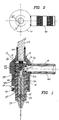
- the present quick change nozzle assembly is shown in cross-section.
- the assembly comprises a stepped cylindrical shaped nozzle cap 10 having an axial cap bore 11 therethrough.
- a nozzle tube 12 is inserted in one end of the axial cap bore 11 and retained therein by means of a thread 13.
- the nozzle tube 12 is in sealing engagement with the axial cap bore 11 by means of an "O" ring 44.
- Inserted in the opposite end of the axial cap bore 11 from the nozzle tube end is a nozzle body 20.
- the nozzle body 20 has a nozzle body bore 29 into which is inserted a focus tube 30 and a wear insert 35.
- the focus tube 30 and the wear insert 35 are retained within the nozzle body bore 29 by means of set screws 20 and 21 respectively.
- the nozzle body 20 is further retained within the axial cap bore 11 by means of an interlocking step 23 on the nozzle body 20 and a locking land 24 on the nozzle cap 10.
- Orientation of the nozzle body 20 in the axial cap bore 11 is accomplished by means of a guide pin 22 which co-operates with a guide groove 25 (best seen in Fig. 8).
- the guide pin 22 and the guide groove 25 co-operate to align the abrasive inlet in the wear insert 35 with an abrasive inlet bore 41 contained in a feed tube handle 40.
- An orifice 15 is disposed in a small longitudinal orifice bore 16 within the nozzle body 20 for alignment purposes and is compressed for retention between the nozzle body 20 and the nozzle tube 12.
- Sealing of the various components is accomplished by means of a number of “O” rings, in particular “O” ring 44 seals the nozzle tube in the threaded bore 13, “O” ring 46 is used to seal the threaded connection between the handle 40 and the nozzle cap 10, “O” ring 47 seals the other end of the axial cap bore 11 and the nozzle body, and a pair of “O” rings 48, 49, seal the abrasive inlet within the axial cap bore 11.
- the handle 40 may be used to rotate the nozzle about the nozzle tube 12.
- a wrench flat 55 may also be provided for this purpose but in the preferred embodiment the handle 40 may be used as a means of rotation.
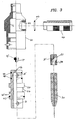
- Fig. 3 shows the assembly of components for the nozzle.
- the nozzle tube is normally fixed on an X-Y computer controlled carrier or the like and the nozzle cap 10 is screwed onto the nozzle tube by means of the thread 13.
- the handle 40 which contains the abrasive inlet bore 41, is attached to the nozzle body by means of a threaded connection 42.
- a threaded connection 42 to replace the nozzle components it is simply necessary to rotate the nozzle cap 10 by means of the handle thereby backing the nozzle tube 12 slightly out of the threaded bore 13. As best seen in Fig. 8, this permits the nozzle body 20 to be rotated within the axial cap bore 11 from the locked position 50 in the guide groove 25 to the unlocked and release channel position 51 in the guide groove as controlled by the guide pin 22.
- the locking step 23 can clear the locking lands 24 of the nozzle cap permitting the nozzle body 20 to be removed.
- the orifice 15 may be replaced in the orifice bore 16.
- the set screws 31 and 32 may be backed out of their respective threaded bores 33 and 34. This permits the focus tube and the wear insert to be removed from the nozzle body bore 29.
- the design of the nozzle body 20 permits assembly of the orifice 15 on the external top surface by insertion of the nozzle stem 17 into the orifice bore 16. This eliminates the need to fumble with alignment and insertion of the small nozzle part in a recess as is common in the prior art.
- the wear insert 35 is inserted in the nozzle body bore 29 and is aligned with the abrasive inlet 27 facing the abrasive inlet bore 41.
- the focus tube is then inserted and clamped in place by means of the set screws 31 and 32.
- the nozzle body 20 may then be reinserted in the nozzle cap 10 by simply aligning the guide groove 25, release point 51, with the guide pin and inserting the nozzle body into the nozzle cap.
- the nozzle body 20 may be rotated to the lock position as controlled by the lock point 50 in guide groove 25.
- the handle 40 may then be utilized to rotate the nozzle cap to increasingly threadingly engage the nozzle tube 12 thereby clamping the orifice 15 securely between the nozzle tube and the nozzle body.
- a spare nozzle body may be assembled which may be rapidly inserted in the nozzle cap as previously described.
Landscapes
- Engineering & Computer Science (AREA)
- Mechanical Engineering (AREA)
- Perforating, Stamping-Out Or Severing By Means Other Than Cutting (AREA)
- Nozzles (AREA)
Applications Claiming Priority (2)
| Application Number | Priority Date | Filing Date | Title |
|---|---|---|---|
| US655066 | 1996-05-29 | ||
| US08/655,066 US5794858A (en) | 1996-05-29 | 1996-05-29 | Quick assembly waterjet nozzle |
Publications (3)
| Publication Number | Publication Date |
|---|---|
| EP0810038A2 true EP0810038A2 (fr) | 1997-12-03 |
| EP0810038A3 EP0810038A3 (fr) | 1999-04-14 |
| EP0810038B1 EP0810038B1 (fr) | 2004-01-28 |
Family
ID=24627364
Family Applications (1)
| Application Number | Title | Priority Date | Filing Date |
|---|---|---|---|
| EP97303601A Expired - Lifetime EP0810038B1 (fr) | 1996-05-29 | 1997-05-28 | Buse à changement rapide pour le découpage au jet d'eau |
Country Status (3)
| Country | Link |
|---|---|
| US (1) | US5794858A (fr) |
| EP (1) | EP0810038B1 (fr) |
| DE (1) | DE69727338T2 (fr) |
Cited By (11)
| Publication number | Priority date | Publication date | Assignee | Title |
|---|---|---|---|---|
| EP0983823A1 (fr) * | 1997-02-04 | 2000-03-08 | Jet Edge, a Division of TC/American Monorail, Inc. | Tête de coupe pour ensemble de découpe au jet d'eau |
| WO2002038337A1 (fr) * | 2000-11-10 | 2002-05-16 | United States Filter Corporation | Vannes de regulation |
| WO2004037108A1 (fr) * | 2002-10-23 | 2004-05-06 | Kaltenbach & Voigt Gmbh & Co. Kg | Canule pour piece a main utilisee en medecine ou en medecine dentaire, pour pulveriser un milieu d'ecoulement abrasif |
| WO2005110614A1 (fr) * | 2004-05-18 | 2005-11-24 | Lind Finance & Development Ab | Limitation de rotation pour arbre de broche |
| EP2145689A1 (fr) | 2008-07-16 | 2010-01-20 | VLN Advanced Technologies Inc. | Procédé et appareil de préparation de surfaces avec un jet d'eau à impulsion haute fréquence |
| WO2011042244A2 (fr) | 2009-10-06 | 2011-04-14 | Sulzer Metco (Us) Inc. | Procédé et appareil de préparation de surfaces d'alésage de cylindre en vue d'un revêtement par projection thermique au moyen d'un jet d'eau pulsé |
| US8006915B2 (en) | 2003-11-03 | 2011-08-30 | Vijay Mohan M | Ultrasonic waterjet apparatus |
| CN103481204A (zh) * | 2013-09-28 | 2014-01-01 | 宁波大隆机器制造有限公司 | 用于高压水射流常温除鳞工艺的喷嘴 |
| EP3391996A1 (fr) * | 2017-04-21 | 2018-10-24 | Microwaterjet AG | Procédé et dispositif de traitement d'une pièce à usiner au moyen d'un jet de liquide abrasif |
| USD947366S1 (en) | 2016-12-15 | 2022-03-29 | Water Pik, Inc. | Oral irrigator handle |
| US12053338B2 (en) | 2017-03-16 | 2024-08-06 | Water Pik, Inc. | Oral irrigator with back flow prevention |
Families Citing this family (28)
| Publication number | Priority date | Publication date | Assignee | Title |
|---|---|---|---|---|
| DE19640921C1 (de) * | 1996-10-04 | 1997-11-27 | Saechsische Werkzeug Und Sonde | Modularer Abrasivmittelwasserstrahl-Schneidkopf |
| US6425805B1 (en) * | 1999-05-21 | 2002-07-30 | Kennametal Pc Inc. | Superhard material article of manufacture |
| US6502767B2 (en) * | 2000-05-03 | 2003-01-07 | Asb Industries | Advanced cold spray system |
| US6601783B2 (en) * | 2001-04-25 | 2003-08-05 | Dennis Chisum | Abrasivejet nozzle and insert therefor |
| US7464630B2 (en) * | 2001-08-27 | 2008-12-16 | Flow International Corporation | Apparatus for generating and manipulating a high-pressure fluid jet |
| JP2005500175A (ja) * | 2001-08-27 | 2005-01-06 | フロー インターナショナル コーポレイション | 高圧流体ジェットを発生するための装置 |
| US20040227021A1 (en) * | 2003-05-16 | 2004-11-18 | Bowles Fluidics Corporation | Tool-free, quick disconnect, nozzle assembly |
| US20070202781A1 (en) * | 2006-02-28 | 2007-08-30 | Media Blast & Abrasives, Inc. | Blast media nozzle and nozzle assembly |
| US7922566B2 (en) * | 2006-08-02 | 2011-04-12 | Kmt Waterjet Systems Inc. | Cutting head for fluid jet machine with indexing focusing device |
| US7757971B2 (en) * | 2007-05-11 | 2010-07-20 | Schlumberger Technology Corporation | Diamond nozzle |
| US20100210186A1 (en) * | 2009-02-18 | 2010-08-19 | Lai International, Inc. | Multi-head fluid jet cutting system |
| DE102010051227A1 (de) | 2010-11-12 | 2012-05-16 | Dental Care Innovation Gmbh | Düse zur Abstrahlung von flüssigen Reinigungsmitteln mit darin dispergierten abrasiven Partikeln |
| US8783146B2 (en) * | 2011-11-04 | 2014-07-22 | Kmt Waterjet Systems Inc. | Abrasive waterjet focusing tube retainer and alignment |
| US20140004776A1 (en) * | 2012-06-29 | 2014-01-02 | Gary N. Bury | Abrasivejet Cutting Head With Enhanced Abrasion-Resistant Cartridge |
| WO2014062057A1 (fr) * | 2012-10-15 | 2014-04-24 | Inflotek B.V. | Buse de découpe de largeur fine dans un système de découpe à jet abrasif |
| US9272437B2 (en) * | 2012-10-31 | 2016-03-01 | Flow International Corporation | Fluid distribution components of high-pressure fluid jet systems |
| ITTO20130363A1 (it) * | 2013-05-06 | 2014-11-07 | Biesse Spa | Testa operatrice del tipo "water-jet" per il taglio di materiali con getto idro-abrasivo ad elevata pressione |
| US9884406B2 (en) | 2014-01-15 | 2018-02-06 | Flow International Corporation | High-pressure waterjet cutting head systems, components and related methods |
| GB201401265D0 (en) * | 2014-01-26 | 2014-03-12 | Miller Donald S | Composite focus tubes |
| US9638357B1 (en) | 2015-06-24 | 2017-05-02 | Omax Corporation | Mechanical processing of high aspect ratio metallic tubing and related technology |
| US10596717B2 (en) | 2015-07-13 | 2020-03-24 | Flow International Corporation | Methods of cutting fiber reinforced polymer composite workpieces with a pure waterjet |
| US10801651B2 (en) * | 2018-02-15 | 2020-10-13 | Omax Corporation | Ultrahigh pressure fitting with recessed sealing surface and related technology |
| CN110480523B (zh) * | 2019-08-30 | 2021-02-05 | 南京晨光集团有限责任公司 | 一种智能机器人生产用喷砂用自动更换喷头装置 |
| US12403621B2 (en) | 2019-12-20 | 2025-09-02 | Hypertherm, Inc. | Motorized systems and associated methods for controlling an adjustable dump orifice on a liquid jet cutting system |
| EP4127527A1 (fr) | 2020-03-24 | 2023-02-08 | Hypertherm, Inc. | Joint haute pression pour système de coupe à jet de liquide |
| CN115768597A (zh) | 2020-03-26 | 2023-03-07 | 海别得公司 | 自由调速止回阀 |
| KR20230005840A (ko) | 2020-03-30 | 2023-01-10 | 하이퍼썸, 인크. | 다기능 접속 종방향 단부들을 갖는 액체 제트 펌프를 위한 실린더 |
| CN115091367A (zh) * | 2022-06-21 | 2022-09-23 | 武汉大学 | 双空化磨料射流的实验装置及实验方法 |
Family Cites Families (13)
| Publication number | Priority date | Publication date | Assignee | Title |
|---|---|---|---|---|
| DE1500603A1 (de) * | 1966-07-15 | 1969-06-12 | Spraying Systems Co | Spritzduese |
| US4478368A (en) * | 1982-06-11 | 1984-10-23 | Fluidyne Corporation | High velocity particulate containing fluid jet apparatus and process |
| US4494735A (en) * | 1983-11-16 | 1985-01-22 | Swiss Aluminium Ltd. | Apparatus for degassing molten metal |
| US4817874A (en) * | 1985-10-31 | 1989-04-04 | Flow Systems, Inc. | Nozzle attachment for abrasive fluid-jet cutting systems |
| US4872615A (en) * | 1988-02-29 | 1989-10-10 | Ingersoll-Rand Company | Fluid-jet-cutting nozzle assembly |
| US4832266A (en) * | 1988-04-29 | 1989-05-23 | Marvin Lyle E | Fluid-jet-cutting nozzle assembly |
| US5054249A (en) * | 1988-11-23 | 1991-10-08 | Rankin George J | Method and apparatus for liquid-abrasive blast cleaning |
| US5092085A (en) * | 1989-11-03 | 1992-03-03 | Flow International Corporation | Liquid abrasive cutting jet cartridge and method |
| US5018670A (en) * | 1990-01-10 | 1991-05-28 | Possis Corporation | Cutting head for water jet cutting machine |
| CA2039681C (fr) * | 1990-04-05 | 2001-02-20 | Richard J. Hamilton | Assemblage d'ajutage a desaccouplement rapide |
| US5255853A (en) * | 1991-04-02 | 1993-10-26 | Ingersoll-Rand Company | Adjustable fluid jet cleaner |
| GB2258416B (en) * | 1991-07-27 | 1995-04-19 | Brian David Dale | Nozzle for abrasive cleaning or cutting |
| US5320289A (en) * | 1992-08-14 | 1994-06-14 | National Center For Manufacturing Sciences | Abrasive-waterjet nozzle for intelligent control |
-
1996
- 1996-05-29 US US08/655,066 patent/US5794858A/en not_active Expired - Lifetime
-
1997
- 1997-05-28 EP EP97303601A patent/EP0810038B1/fr not_active Expired - Lifetime
- 1997-05-28 DE DE69727338T patent/DE69727338T2/de not_active Expired - Lifetime
Cited By (19)
| Publication number | Priority date | Publication date | Assignee | Title |
|---|---|---|---|---|
| EP0983823A1 (fr) * | 1997-02-04 | 2000-03-08 | Jet Edge, a Division of TC/American Monorail, Inc. | Tête de coupe pour ensemble de découpe au jet d'eau |
| WO2002038337A1 (fr) * | 2000-11-10 | 2002-05-16 | United States Filter Corporation | Vannes de regulation |
| US6607175B1 (en) | 2000-11-10 | 2003-08-19 | United States Filter Corporation | Media control valve |
| WO2004037108A1 (fr) * | 2002-10-23 | 2004-05-06 | Kaltenbach & Voigt Gmbh & Co. Kg | Canule pour piece a main utilisee en medecine ou en medecine dentaire, pour pulveriser un milieu d'ecoulement abrasif |
| WO2004037109A3 (fr) * | 2002-10-23 | 2004-07-01 | Kaltenbach & Voigt | Canule conçue pour une piece a main medicale ou medico-dentaire pour pulveriser une substance d'ecoulement abrasive |
| US8006915B2 (en) | 2003-11-03 | 2011-08-30 | Vijay Mohan M | Ultrasonic waterjet apparatus |
| US8360337B2 (en) | 2003-11-03 | 2013-01-29 | Pratt & Whitney Military Aftermarket Services, Inc. | Ultrasonic waterjet apparatus |
| US8387894B2 (en) | 2003-11-03 | 2013-03-05 | Pratt & Whitney Military Aftermarket Services, Inc. | Ultrasonic waterjet apparatus |
| WO2005110614A1 (fr) * | 2004-05-18 | 2005-11-24 | Lind Finance & Development Ab | Limitation de rotation pour arbre de broche |
| EP2540402A2 (fr) | 2008-07-16 | 2013-01-02 | VLN Advanced Technologies Inc. | Procédé et appareil de préparation de surfaces avec un jet dýeau à impulsion haute fréquence |
| EP2540401A2 (fr) | 2008-07-16 | 2013-01-02 | VLN Advanced Technologies Inc. | Procédé et appareil de préparation de surfaces avec un jet dýeau à impulsion haute fréquence |
| EP2145689A1 (fr) | 2008-07-16 | 2010-01-20 | VLN Advanced Technologies Inc. | Procédé et appareil de préparation de surfaces avec un jet d'eau à impulsion haute fréquence |
| EP3357583A1 (fr) | 2008-07-16 | 2018-08-08 | VLN Advanced Technologies Inc. | Procédé et appareil de préparation de surfaces avec un jet d'eau à impulsion haute fréquence |
| WO2011042244A2 (fr) | 2009-10-06 | 2011-04-14 | Sulzer Metco (Us) Inc. | Procédé et appareil de préparation de surfaces d'alésage de cylindre en vue d'un revêtement par projection thermique au moyen d'un jet d'eau pulsé |
| CN103481204A (zh) * | 2013-09-28 | 2014-01-01 | 宁波大隆机器制造有限公司 | 用于高压水射流常温除鳞工艺的喷嘴 |
| CN103481204B (zh) * | 2013-09-28 | 2016-04-06 | 宁波大隆机器制造有限公司 | 用于高压水射流常温除鳞工艺的喷嘴 |
| USD947366S1 (en) | 2016-12-15 | 2022-03-29 | Water Pik, Inc. | Oral irrigator handle |
| US12053338B2 (en) | 2017-03-16 | 2024-08-06 | Water Pik, Inc. | Oral irrigator with back flow prevention |
| EP3391996A1 (fr) * | 2017-04-21 | 2018-10-24 | Microwaterjet AG | Procédé et dispositif de traitement d'une pièce à usiner au moyen d'un jet de liquide abrasif |
Also Published As
| Publication number | Publication date |
|---|---|
| EP0810038A3 (fr) | 1999-04-14 |
| DE69727338T2 (de) | 2004-11-04 |
| DE69727338D1 (de) | 2004-03-04 |
| EP0810038B1 (fr) | 2004-01-28 |
| US5794858A (en) | 1998-08-18 |
Similar Documents
| Publication | Publication Date | Title |
|---|---|---|
| EP0810038B1 (fr) | Buse à changement rapide pour le découpage au jet d'eau | |
| US5934569A (en) | Fluid nozzle having a swirl unit and orifice plate, and means for facilitating assembly thereof | |
| US4817874A (en) | Nozzle attachment for abrasive fluid-jet cutting systems | |
| US4545157A (en) | Center feeding water jet/abrasive cutting nozzle assembly | |
| US5333790A (en) | Quick disconnect nozzle apparatus | |
| KR102675036B1 (ko) | 공구 시스템 | |
| US4836455A (en) | Fluid-jet-cutting nozzle assembly | |
| US7004692B2 (en) | Rotary cutting tool | |
| US5320289A (en) | Abrasive-waterjet nozzle for intelligent control | |
| JPS6121754A (ja) | スプレ−ノズル | |
| US5522605A (en) | Collet chuck having parpallel force loaded bearing | |
| JPH03208559A (ja) | ウォータジェット式切削装置用切削ヘッド | |
| EP2987575B1 (fr) | Dispositif de serrage | |
| CZ287496A3 (en) | Tool system | |
| GB2108408A (en) | Quick disconnect nozzle | |
| US4842337A (en) | Mining bit and holder | |
| US9833846B2 (en) | Rotary cutting tool with high-pressure, threaded coolant cap | |
| US5542794A (en) | Multi-handed milling cutter having indexable wedges and inserts | |
| US4915454A (en) | Mining bit and holder | |
| CN101132872B (zh) | 筒夹和锁紧螺帽 | |
| EP0722797B1 (fr) | Arrangement pour des outils dans des espaces restreintes | |
| DE3405211A1 (de) | Schneidwerkzeug fuer spanabhebende bearbeitung | |
| US5454515A (en) | Spray tip for flat orifice tip | |
| US5388936A (en) | Tool holder | |
| EP1954406B1 (fr) | Assemblage de monture d orifice de couple nul |
Legal Events
| Date | Code | Title | Description |
|---|---|---|---|
| PUAI | Public reference made under article 153(3) epc to a published international application that has entered the european phase |
Free format text: ORIGINAL CODE: 0009012 |
|
| AK | Designated contracting states |
Kind code of ref document: A2 Designated state(s): CH DE FR GB LI SE |
|
| PUAL | Search report despatched |
Free format text: ORIGINAL CODE: 0009013 |
|
| AK | Designated contracting states |
Kind code of ref document: A3 Designated state(s): CH DE FR GB LI SE |
|
| RHK1 | Main classification (correction) |
Ipc: B24C 5/04 |
|
| 17P | Request for examination filed |
Effective date: 19990924 |
|
| 17Q | First examination report despatched |
Effective date: 20030210 |
|
| GRAP | Despatch of communication of intention to grant a patent |
Free format text: ORIGINAL CODE: EPIDOSNIGR1 |
|
| GRAS | Grant fee paid |
Free format text: ORIGINAL CODE: EPIDOSNIGR3 |
|
| GRAA | (expected) grant |
Free format text: ORIGINAL CODE: 0009210 |
|
| AK | Designated contracting states |
Kind code of ref document: B1 Designated state(s): CH DE FR GB LI SE |
|
| PG25 | Lapsed in a contracting state [announced via postgrant information from national office to epo] |
Ref country code: LI Free format text: LAPSE BECAUSE OF FAILURE TO SUBMIT A TRANSLATION OF THE DESCRIPTION OR TO PAY THE FEE WITHIN THE PRESCRIBED TIME-LIMIT Effective date: 20040128 Ref country code: FR Free format text: LAPSE BECAUSE OF FAILURE TO SUBMIT A TRANSLATION OF THE DESCRIPTION OR TO PAY THE FEE WITHIN THE PRESCRIBED TIME-LIMIT Effective date: 20040128 Ref country code: CH Free format text: LAPSE BECAUSE OF FAILURE TO SUBMIT A TRANSLATION OF THE DESCRIPTION OR TO PAY THE FEE WITHIN THE PRESCRIBED TIME-LIMIT Effective date: 20040128 |
|
| REG | Reference to a national code |
Ref country code: GB Ref legal event code: FG4D |
|
| REG | Reference to a national code |
Ref country code: CH Ref legal event code: EP |
|
| REF | Corresponds to: |
Ref document number: 69727338 Country of ref document: DE Date of ref document: 20040304 Kind code of ref document: P |
|
| RAP2 | Party data changed (patent owner data changed or rights of a patent transferred) |
Owner name: KMT WATERJET SYSTEMS, INC. |
|
| REG | Reference to a national code |
Ref country code: SE Ref legal event code: TRGR |
|
| REG | Reference to a national code |
Ref country code: CH Ref legal event code: PL |
|
| PLBE | No opposition filed within time limit |
Free format text: ORIGINAL CODE: 0009261 |
|
| STAA | Information on the status of an ep patent application or granted ep patent |
Free format text: STATUS: NO OPPOSITION FILED WITHIN TIME LIMIT |
|
| 26N | No opposition filed |
Effective date: 20041029 |
|
| EN | Fr: translation not filed | ||
| PGFP | Annual fee paid to national office [announced via postgrant information from national office to epo] |
Ref country code: GB Payment date: 20160527 Year of fee payment: 20 Ref country code: DE Payment date: 20160527 Year of fee payment: 20 |
|
| PGFP | Annual fee paid to national office [announced via postgrant information from national office to epo] |
Ref country code: SE Payment date: 20160527 Year of fee payment: 20 |
|
| REG | Reference to a national code |
Ref country code: DE Ref legal event code: R071 Ref document number: 69727338 Country of ref document: DE |
|
| REG | Reference to a national code |
Ref country code: GB Ref legal event code: PE20 Expiry date: 20170527 |
|
| REG | Reference to a national code |
Ref country code: SE Ref legal event code: EUG |
|
| PG25 | Lapsed in a contracting state [announced via postgrant information from national office to epo] |
Ref country code: GB Free format text: LAPSE BECAUSE OF EXPIRATION OF PROTECTION Effective date: 20170527 |