EP0810117A1 - Dispositif d'éclairage ou de signalisation de véhicule automobile, comportant des moyens de fixation perfectionnes - Google Patents
Dispositif d'éclairage ou de signalisation de véhicule automobile, comportant des moyens de fixation perfectionnes Download PDFInfo
- Publication number
- EP0810117A1 EP0810117A1 EP97401147A EP97401147A EP0810117A1 EP 0810117 A1 EP0810117 A1 EP 0810117A1 EP 97401147 A EP97401147 A EP 97401147A EP 97401147 A EP97401147 A EP 97401147A EP 0810117 A1 EP0810117 A1 EP 0810117A1
- Authority
- EP
- European Patent Office
- Prior art keywords
- housing
- tab
- fixing
- arrangement
- barrel
- Prior art date
- Legal status (The legal status is an assumption and is not a legal conclusion. Google has not performed a legal analysis and makes no representation as to the accuracy of the status listed.)
- Granted
Links
- 230000011664 signaling Effects 0.000 title claims description 9
- 230000005489 elastic deformation Effects 0.000 claims abstract description 3
- 238000000465 moulding Methods 0.000 claims description 3
- 238000004519 manufacturing process Methods 0.000 description 3
- 230000007547 defect Effects 0.000 description 1
- 230000003100 immobilizing effect Effects 0.000 description 1
- 238000009434 installation Methods 0.000 description 1
Images
Classifications
-
- B—PERFORMING OPERATIONS; TRANSPORTING
- B60—VEHICLES IN GENERAL
- B60Q—ARRANGEMENT OF SIGNALLING OR LIGHTING DEVICES, THE MOUNTING OR SUPPORTING THEREOF OR CIRCUITS THEREFOR, FOR VEHICLES IN GENERAL
- B60Q1/00—Arrangement of optical signalling or lighting devices, the mounting or supporting thereof or circuits therefor
- B60Q1/02—Arrangement of optical signalling or lighting devices, the mounting or supporting thereof or circuits therefor the devices being primarily intended to illuminate the way ahead or to illuminate other areas of way or environments
- B60Q1/04—Arrangement of optical signalling or lighting devices, the mounting or supporting thereof or circuits therefor the devices being primarily intended to illuminate the way ahead or to illuminate other areas of way or environments the devices being headlights
- B60Q1/0408—Arrangement of optical signalling or lighting devices, the mounting or supporting thereof or circuits therefor the devices being primarily intended to illuminate the way ahead or to illuminate other areas of way or environments the devices being headlights built into the vehicle body, e.g. details concerning the mounting of the headlamps on the vehicle body
- B60Q1/0433—Arrangement of optical signalling or lighting devices, the mounting or supporting thereof or circuits therefor the devices being primarily intended to illuminate the way ahead or to illuminate other areas of way or environments the devices being headlights built into the vehicle body, e.g. details concerning the mounting of the headlamps on the vehicle body the housing being fastened onto the vehicle body using screws
-
- B—PERFORMING OPERATIONS; TRANSPORTING
- B60—VEHICLES IN GENERAL
- B60Q—ARRANGEMENT OF SIGNALLING OR LIGHTING DEVICES, THE MOUNTING OR SUPPORTING THEREOF OR CIRCUITS THEREFOR, FOR VEHICLES IN GENERAL
- B60Q1/00—Arrangement of optical signalling or lighting devices, the mounting or supporting thereof or circuits therefor
- B60Q1/02—Arrangement of optical signalling or lighting devices, the mounting or supporting thereof or circuits therefor the devices being primarily intended to illuminate the way ahead or to illuminate other areas of way or environments
- B60Q1/04—Arrangement of optical signalling or lighting devices, the mounting or supporting thereof or circuits therefor the devices being primarily intended to illuminate the way ahead or to illuminate other areas of way or environments the devices being headlights
- B60Q1/0408—Arrangement of optical signalling or lighting devices, the mounting or supporting thereof or circuits therefor the devices being primarily intended to illuminate the way ahead or to illuminate other areas of way or environments the devices being headlights built into the vehicle body, e.g. details concerning the mounting of the headlamps on the vehicle body
- B60Q1/045—Arrangement of optical signalling or lighting devices, the mounting or supporting thereof or circuits therefor the devices being primarily intended to illuminate the way ahead or to illuminate other areas of way or environments the devices being headlights built into the vehicle body, e.g. details concerning the mounting of the headlamps on the vehicle body with provision for adjusting the alignment of the headlamp housing with respect to the vehicle body
Definitions
- the present invention relates to a device for fixing a signaling and / or lighting device to the body of a vehicle, making it possible to make up for the different games in translation and in rotation, in particular due to manufacturing tolerances, in particular of the body.
- the Applicant has proposed a fixing device allowing adjustment along three axes of the relative position of a signaling and / or lighting device housing to the vehicle body comprising two sliding elements relative to each other, a clamping screw and means for immobilizing the assembly in a locked position.
- this type of device has the drawback of requiring many parts, and in addition to the tedious operations during assembly and disassembly of the device, which complicates the installation of the signaling and / or lighting device and increases the costs of production.
- the angular backlash adjustments are not always perfectly carried out.
- Another commonly used fixing device comprises a flexible tab, integral with the housing of the signaling and / or lighting device and receiving a screw cooperating with a support for the bodywork.
- This known device is simple to use and inexpensive, but is ill-suited to a wide variety of positioning faults and in particular to a defect in angular position of the surfaces of the housing and of the vehicle body.
- the object of the present invention is to provide a device for fixing a signaling and / or lighting device, simple and economical, and whose ability to make up for play is significantly improved.
- Another object of the invention is to provide a fixing device allowing the mounting and dismounting of a housing on the vehicle body in a simple and rapid manner.
- the device of the invention comprises a flexible tab, integral with the housing and supporting a fixing arrangement, and is characterized in that said tab is produced in one piece with the housing and connected to the latter at two opposite ends, in that said fixing arrangement is located in an intermediate part of said tab, and in that said tab has a sinuous profile ensuring, by elastic deformation, a degree of freedom of said fixing arrangement in translation along three axes as well as tilting.
- the tab extends along a wall of the housing between two ribs projecting from said wall, and has at least three curved zones and a widened curved zone at the level of said arrangement, located substantially halfway from both ends of the tab.
- said fixing arrangement consists of a barrel having a bearing face with an arrangement of the body and traversed by a screw, and the housing and the fixing device are produced by molding.
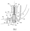
- the device 10 of the invention shown in Figure 1 is made in one piece (for example molded) with the housing 100 of a motor vehicle headlight and mounted on the body 200 of the vehicle.
- the device 10 mainly comprises two ribs 120 and 125 projecting downwards from an attachment zone 110 of the housing 100 of the projector, a thin sinuous tab 130 extending essentially transversely between the two ribs and having in its middle a fixing barrel 140, and a screw 150 passing through the fixing barrel and cooperating with a fixing support 250 secured to the body.
- the ribs 120 and 125 are of elongated shape and extend substantially vertically at different heights.
- the front end 121 in the direction of screwing of the rib 120 is substantially in alignment in the lateral direction of the rear end 126 of the rib 125, and the sinuous tab 130 extends between these ends along the area 110 of attachment of the housing and slightly spaced downward relative thereto.
- the sinuous tab is of substantially constant width between each of its two ends 121 and 126 and the fixing barrel 140, and it has a slight bulge 138 below the barrel 140.
- the tab is connected to the barrel of fixing 140 substantially in the middle in the axial direction.
- the tab has in vertical section four alternating curved zones 131 to 134, the curved zone 133 being enlarged to include the barrel 140.
- these zones are curved around axes of curvature generally perpendicular to the adjacent wall of the housing, and in this case vertical.
- the fixing barrel 140 provided on the tab 130 is cylindrical and has a bore 141 for the passage of the screw 150, emerging at the level of two bearing faces 142 and 145.
- the two faces are perpendicular to the axis of the cylinder, and the bore is centered on the cylinder axis.
- the diameter of the bore 141 is slightly greater than the diameter of the screw 150 and allows its free passage.
- the fixing support 250 integral with the body, is for example cylindrical and has a thread 251 allowing the screw 150 to be screwed.
- the outside diameters of the fixing support 250 and of the barrel 140 are chosen large enough to produce a large contact surface, and therefore stable support between the barrel and the support.
- the attachment zone 110 which is near the tab 130 and the barrel 140, has a concavity 110a in the vicinity of the barrel to allow the free movement of the latter.
- the proximity of the barrel 140 with the housing advantageously gives the entire device good firmness of attachment and a reduced bulk.
- the device which has just been described is used in the following manner, during the mounting of the projector.
- the fixing device 10 of the housing 100 of the headlight is placed on the vehicle body, at the level of the support 250 of the body.
- the screw 150 is introduced into the barrel 140 of the device and screwed into the support 250, until the face 145 of the fixing barrel bears against the face 252 of the body support.
- the sinuous shape of the tab and its flexibility give the barrel good mobility in translation and rotation, to compensate for deviations due to tolerances while ensuring good firmness of the binding.
- the fixing of the housing 100 to the body 200 can be carried out with any number of fixing devices.
Landscapes
- Engineering & Computer Science (AREA)
- Mechanical Engineering (AREA)
- Lighting Device Outwards From Vehicle And Optical Signal (AREA)
- Non-Portable Lighting Devices Or Systems Thereof (AREA)
Abstract
Description
- La présente invention concerne un dispositif de fixation d'un dispositif de signalisation et/ou d'éclairage sur la carrosserie d'un véhicule, permettant de rattraper les différents jeux en translation et en rotation, notamment dus aux tolérances de fabrication, en particulier de la carrosserie.
- Pour des raisons essentiellement esthétiques, les constructeurs automobiles recherchent depuis quelques années à intégrer précisément les feux et projecteurs aux formes du véhicule, afin de rattraper les écarts dus aux tolérances de fabrication.
- Il existe dans l'état de la technique certains dispositifs de fixation qui comprennent plusieurs éléments rapportés entre le boîtier ou le socle du dispositif de signalisation et/ou d'éclairage et la carrosserie du véhicule.
- Ainsi dans le document FR-A-2 719 269, la Demanderesse a proposé un dispositif de fixation permettant un réglage selon trois axes de la position relative d'un boîtier de dispositif de signalisation et/ou d'éclairage à la carrosserie du véhicule comprenant deux éléments coulissants l'un par rapport à l'autre, une vis de serrage et des moyens d'immobilisation de l'ensemble dans une position de blocage.
- Mais ce type de dispositif a l'inconvénient de nécessiter de nombreuses pièces, et en corrollaire des opérations fastidieuses lors du montage et du démontage du dispositif, ce qui complique la pose du dispositif de signalisation et/ou d'éclairage et accroît les coûts de production. En outre, les rattrapages de jeux angulaires ne sont pas toujours parfaitement réalisés.
- Un autre dispositif de fixation communément utilisé comprend une patte souple, solidaire du boîtier du dispositif de signalisation et/ou d'éclairage et recevant une vis coopérant avec un support de la carrosserie.
- Ce dispositif connu est simple d'utilisation et peu coûteux, mais s'adapte mal à une grande variété de défauts de positionnements et en particulier à un défaut de position angulaire des surfaces du boîtier et de la carrosserie du véhicule.
- L'objet de la présente invention est de proposer un dispositif de fixation d'un dispositif de signalisation et/ou d'éclairage, simple et économique, et dont l'aptitude à rattraper les jeux soit nettement améliorée.
- Un autre but de l'invention est de proposer un dispositif de fixation permettant le montage et le démontage d'un boîtier sur la carrosserie du véhicule de façon simple et rapide.
- Le dispositif de l'invention comprend une patte flexible, solidaire du boîtier et supportant un aménagement de fixation, et se caractérise en ce que ladite patte est réalisée d'un seul tenant avec le boîtier et reliée à celui-ci en deux extrémités opposées, en ce que ledit aménagement de fixation se trouve en une partie intermédiaire de ladite patte, et en ce que ladite patte présente un profil sinueux assurant, par déformation élastique, un degré de liberté dudit aménagement de fixation en translation selon trois axes ainsi qu'en basculement.
- De préférence, la patte s'étend le long d'une paroi du boîtier entre deux nervures en saillie à partir de ladite paroi, et présente au moins trois zones courbes et une zone courbe élargie au niveau dudit aménagement, située sensiblement à mi-chemin des deux extrémités de la patte.
- Avantageusement, ledit aménagement de fixation consiste en un canon possédant une face d'appui avec un aménagement de la carrosserie et traversé par une vis, et le boîtier ainsi que le dispositif de fixation sont réalisés par moulage.
- D'autres caractéristiques et avantages de l'invention apparaîtront à la lecture de la description qui suit. Cette description est purement illustrative et non limitative et doit être lue en regard des dessins annexés sur lesquels :
- . la figure 1 est une vue de dessus en coupe du dispositif de fixation d'un boîtier projecteur monté sur la carrosserie du véhicule; et
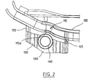
- . la figure 2 est une vue de l'arrière en plan du dispositif de fixation de la figure 1.
- Le dispositif 10 de l'invention représenté sur la figure 1 est réalisé d'un seul tenant (par exemple venu de moulage) avec le boîtier 100 d'un projecteur de véhicule automobile et monté sur la carrosserie 200 du véhicule.
- Le dispositif 10 comprend principalement deux nervures 120 et 125 en saillie vers le bas à partir d'une zone d'attache 110 du boîtier 100 du projecteur, une patte mince sinueuse 130 s'étendant essentiellement transversalement entre les deux nervures et possédant en son milieu un canon de fixation 140, et une vis 150 passant au travers du canon de fixation et coopérant avec un support de fixation 250 solidaire de la carrosserie.
- Les nervures 120 et 125 sont de forme allongée et s'étendent sensiblement verticalement à des hauteurs différentes.
- L'extrémité avant 121 dans le sens du vissage de la nervure 120 est sensiblement dans l'alignement en direction latérale de l'extrémité arrière 126 de la nervure 125, et la patte sinueuse 130 s'étend entre ces extrémités le long de la zone d'attache 110 du boîtier et légèrement espacée vers le bas par rapport à celle-ci. La patte sinueuse est de largeur sensiblement constante entre chacune de ses deux extrémités 121 et 126 et le canon de fixation 140, et elle présente un léger renflement 138 au-dessous du canon 140. La patte se raccorde au canon de fixation 140 sensiblement en son milieu en direction axiale.
- La patte présente en section verticale quatre zones courbes alternées 131 à 134, la zone courbe 133 étant élargie pour englober le canon 140.
- Dans le présent exemple, ces zones sont courbées autour d'axes de courbures généralement perpendiculaires à la paroi adjacente du boîtier, et en l'espèce verticaux.
- On peut bien entendu, en variante, prévoir des courbures autour d'axes d'orientations quelconques, notamment autour d'axes parallèles à la paroi du boîtier.
- Le canon de fixation 140 prévu sur la patte 130 est cylindrique et présente un alésage 141 pour le passage de la vis 150, débouchant au niveau de deux faces d'appui 142 et 145. Les deux faces sont perpendiculaires à l'axe du cylindre, et l'alésage est centré sur l'axe du cylindre.
- Le diamètre de l'alésage 141 est légèrement supérieur au diamètre de la vis 150 et permet son passage libre.
- Le support de fixation 250, solidaire de la carrosserie, est par exemple cylindrique et possède un taraudage 251 permettant le vissage de la vis 150.
- Les diamètres extérieurs du support de fixation 250 et du canon 140 sont choisis suffisamment grands pour réaliser une surface de contact importante, et donc un appui stable entre le canon et le support.
- Sur le boîtier du projecteur, la zone d'attache 110, qui est à proximité de la patte 130 et du canon 140, possède une concavité 110a au voisinage du canon pour permettre le libre débattement de celui-ci.
- La proximité du canon 140 avec le boîtier confère avantageusement à l'ensemble du dispositif une bonne fermeté de fixation et un encombrement réduit.
- Le dispositif qui vient d'être décrit est utilisé de la façon suivante, lors du montage du projecteur.
- Le dispositif de fixation 10 du boîtier 100 du projecteur est placé sur la carrosserie du véhicule, au niveau du support 250 de la carrosserie. La vis 150 est introduite dans le canon 140 du dispositif et vissée dans le support 250, jusqu'à amener la face 145 du canon de fixation en appui contre la face 252 du support de la carrosserie. La forme sinueuse de la patte et sa flexibilité confèrent au canon une bonne mobilité en translation et en rotation, pour compenser les écarts dus aux tolérances tout en assurant une bonne fermeté de la fixation.
- On observera que la fixation du boîtier 100 sur la carrosserie 200 peut être réalisée avec un nombre quelconque de dispositifs de fixation.
- Selon plusieurs variantes, il est possible de réaliser l'ensemble des nervures 120 et 125, de la patte 130 et du canon 140 dans une matière plastique ou dans des matériaux différents pour améliorer la solidité et la mobilité du dispositif.
Claims (10)
- Dispositif de fixation d'un boîtier (100) de dispositif d'éclairage et/ou de signalisation d'un véhicule automobile sur la carrosserie (200) du véhicule, comprenant une patte flexible (130) solidaire du boîtier et supportant un aménagement de fixation (140), caractérisé en ce que ladite patte (130) est réalisée d'un seul tenant avec le boîtier (100) et reliée à celui-ci en deux extrémités (121, 126) opposées, en ce que ledit aménagement de fixation (140) se trouve en une partie intermédiaire de ladite patte (130), et en ce que ladite patte présente un profil sinueux apte par déformation élastique à donner un degré de liberté audit aménagement de fixation en translation selon trois axes ainsi qu'en basculement.
- Dispositif selon la revendication 1, caractérisé en ce que la patte (130) s'étend le long d'une paroi (150) du boîtier entre deux nervures (120, 125) espacées en saillie à partir de ladite paroi.
- Dispositif selon la revendication 1 ou 2, caractérisé en ce que la patte (130) présente en section au moins trois zones courbes (131-134).
- Dispositif selon la revendication 3, caractérisé en ce qu'une zone courbe centrale (133) est élargie au niveau dudit aménagement de fixation (140).
- Dispositif selon la revendication 1 ou 2, caractérisé en ce que l'aménagement de fixation (140) est situé sensiblement à mi-chemin entre les deux extrémités de la patte (130).
- Dispositif selon l'une des revendications 1 à 5, caractérisé en ce que ledit aménagement de fixation consiste en un canon (140) possédant une face annulaire plane d'appui (145) contre un aménagement (250) de la carrosserie et apte à être traversé par une vis (150).
- Dispositif selon l'une des revendications 1 à 6, caractérisé en ce que le boîtier (100) est réalisé par moulage de matière plastique, et en ce que le dispositif de fixation est venu de moulage.
- Dispositif selon l'une des revendications 1 à 7, caractérisé en ce que le profil sinueux est défini par une pluralité de courbures autour d'axes de courbure généralement perpendiculaires à une paroi adjacente (110) du boîtier.
- Dispositif selon l'une des revendications 1 à 7, caractérisé en ce que le profil sinueux est défini par une pluralité de courbures autour d'axes de courbure généralement parallèles à une paroi adjacente (110) du boîtier.
- Dispositif d'éclairage et/ou de signalisation de véhicule automobile, caractérisé en ce qu'il comporte un boîtier (100) possédant un dispositif de fixation (10) selon l'une des revendications 1 à 9.
Applications Claiming Priority (2)
| Application Number | Priority Date | Filing Date | Title |
|---|---|---|---|
| FR9606549A FR2749238B1 (fr) | 1996-05-28 | 1996-05-28 | Dispositif d'eclairage ou de signalisation de vehicule automobile, comportant des moyens de fixation perfectionnes |
| FR9606549 | 1996-05-28 |
Publications (2)
| Publication Number | Publication Date |
|---|---|
| EP0810117A1 true EP0810117A1 (fr) | 1997-12-03 |
| EP0810117B1 EP0810117B1 (fr) | 2001-08-22 |
Family
ID=9492478
Family Applications (1)
| Application Number | Title | Priority Date | Filing Date |
|---|---|---|---|
| EP19970401147 Expired - Lifetime EP0810117B1 (fr) | 1996-05-28 | 1997-05-26 | Dispositif de fixation d'un dispositif de signalisation ou d'éclairage d'un vehicule |
Country Status (4)
| Country | Link |
|---|---|
| EP (1) | EP0810117B1 (fr) |
| DE (1) | DE69706232T2 (fr) |
| ES (1) | ES2162209T3 (fr) |
| FR (1) | FR2749238B1 (fr) |
Citations (1)
| Publication number | Priority date | Publication date | Assignee | Title |
|---|---|---|---|---|
| BE537930A (fr) * |
-
1996
- 1996-05-28 FR FR9606549A patent/FR2749238B1/fr not_active Expired - Fee Related
-
1997
- 1997-05-26 DE DE1997606232 patent/DE69706232T2/de not_active Expired - Lifetime
- 1997-05-26 EP EP19970401147 patent/EP0810117B1/fr not_active Expired - Lifetime
- 1997-05-26 ES ES97401147T patent/ES2162209T3/es not_active Expired - Lifetime
Patent Citations (1)
| Publication number | Priority date | Publication date | Assignee | Title |
|---|---|---|---|---|
| BE537930A (fr) * |
Also Published As
| Publication number | Publication date |
|---|---|
| DE69706232D1 (de) | 2001-09-27 |
| ES2162209T3 (es) | 2001-12-16 |
| FR2749238A1 (fr) | 1997-12-05 |
| EP0810117B1 (fr) | 2001-08-22 |
| DE69706232T2 (de) | 2002-06-13 |
| FR2749238B1 (fr) | 1998-08-21 |
Similar Documents
| Publication | Publication Date | Title |
|---|---|---|
| EP1644219B1 (fr) | Bloc projecteur pour vehicule automobile, et vehicule corresppondant | |
| EP0807547B1 (fr) | Fixation de feu sur carrosserie de véhicule automobile, comportant un ressort accordeon | |
| EP1405761B1 (fr) | Capsule d'articulation pour un projecteur d'éclairage de véhicule automobile | |
| FR2588109A1 (fr) | Dispositif de signalisation lumineuse | |
| EP1108452B1 (fr) | Dispositif de liasion entre une fixation de chaussure et une planche de glisse | |
| EP0810117B1 (fr) | Dispositif de fixation d'un dispositif de signalisation ou d'éclairage d'un vehicule | |
| FR2742106A1 (fr) | Phare pour vehicules | |
| EP3208527B1 (fr) | Feu de signalisation avec faisceau focalisant en retrait de la surface extérieure dudit feu | |
| EP1694492A1 (fr) | Agencement pour la fixation amovible d une tige d etira ge sur un coulisseau | |
| FR2666867A1 (fr) | Phare pour vehicules automobiles, dont le reflecteur est dispose a pouvoir etre regle sur un support. | |
| FR2684420A1 (fr) | Cage d'articulation a rotule. | |
| EP3301351A1 (fr) | Support monobloc pour dispositif lumineux avec matrice de micro-miroirs | |
| FR2716710A1 (fr) | Dispositif de fixation d'une source lumineuse dans un support de réception d'un projecteur. | |
| EP0578552B1 (fr) | Projecteur pour véhicule automobile, comprenant un réflecteur orientable | |
| FR2851267A1 (fr) | Dispositif permettant d'associer des barrieres | |
| FR2984461A1 (fr) | Ensemble d'un projecteur pour vehicule automobile et d'au moins un module de remplacement, et procede de remise en etat du projecteur | |
| EP1607271B1 (fr) | Dispositif de traversée de tôle mince | |
| EP1186837B1 (fr) | Dispositif de fixation murale d'un radiateur de chauffage et procédé de fixation d'un tel radiateur | |
| EP0703371B1 (fr) | Système de fixation d'un ensemble sur une colonne, notamment pour la fixation d'un ensemble de commutation électrique sur une colonne de direction de véhicule automobile | |
| FR2805596A1 (fr) | Projecteur de vehicule automobile a masque et reflecteur | |
| FR2801483A1 (fr) | Dispositif d'accrochage d'un rideau sous une tringle | |
| FR2748708A1 (fr) | Fixation de feu sur carrosserie de vehicule automobile, comportant un ressort accordeon | |
| FR2705632A1 (fr) | Balai d'essuie vitre. | |
| FR2742212A1 (fr) | Dispositif d'eclairage baladeur | |
| FR2784645A1 (fr) | Bac de rangement pour coffre de vehicules automobiles |
Legal Events
| Date | Code | Title | Description |
|---|---|---|---|
| PUAI | Public reference made under article 153(3) epc to a published international application that has entered the european phase |
Free format text: ORIGINAL CODE: 0009012 |
|
| AK | Designated contracting states |
Kind code of ref document: A1 Designated state(s): DE ES GB IT |
|
| 17P | Request for examination filed |
Effective date: 19980525 |
|
| RTI1 | Title (correction) |
Free format text: MOUNTING MEANS FOR VEHICLE SIGNALLING OR LIGHTING DEVICE |
|
| GRAG | Despatch of communication of intention to grant |
Free format text: ORIGINAL CODE: EPIDOS AGRA |
|
| 17Q | First examination report despatched |
Effective date: 20001012 |
|
| GRAG | Despatch of communication of intention to grant |
Free format text: ORIGINAL CODE: EPIDOS AGRA |
|
| GRAH | Despatch of communication of intention to grant a patent |
Free format text: ORIGINAL CODE: EPIDOS IGRA |
|
| GRAH | Despatch of communication of intention to grant a patent |
Free format text: ORIGINAL CODE: EPIDOS IGRA |
|
| GRAA | (expected) grant |
Free format text: ORIGINAL CODE: 0009210 |
|
| AK | Designated contracting states |
Kind code of ref document: B1 Designated state(s): DE ES GB IT |
|
| REF | Corresponds to: |
Ref document number: 69706232 Country of ref document: DE Date of ref document: 20010927 |
|
| GBT | Gb: translation of ep patent filed (gb section 77(6)(a)/1977) |
Effective date: 20011116 |
|
| REG | Reference to a national code |
Ref country code: ES Ref legal event code: FG2A Ref document number: 2162209 Country of ref document: ES Kind code of ref document: T3 |
|
| REG | Reference to a national code |
Ref country code: GB Ref legal event code: IF02 |
|
| PLBE | No opposition filed within time limit |
Free format text: ORIGINAL CODE: 0009261 |
|
| STAA | Information on the status of an ep patent application or granted ep patent |
Free format text: STATUS: NO OPPOSITION FILED WITHIN TIME LIMIT |
|
| 26N | No opposition filed | ||
| PGFP | Annual fee paid to national office [announced via postgrant information from national office to epo] |
Ref country code: GB Payment date: 20110426 Year of fee payment: 15 |
|
| PGFP | Annual fee paid to national office [announced via postgrant information from national office to epo] |
Ref country code: DE Payment date: 20120514 Year of fee payment: 16 |
|
| PGFP | Annual fee paid to national office [announced via postgrant information from national office to epo] |
Ref country code: IT Payment date: 20120522 Year of fee payment: 16 |
|
| PGFP | Annual fee paid to national office [announced via postgrant information from national office to epo] |
Ref country code: ES Payment date: 20120524 Year of fee payment: 16 |
|
| GBPC | Gb: european patent ceased through non-payment of renewal fee |
Effective date: 20120526 |
|
| PG25 | Lapsed in a contracting state [announced via postgrant information from national office to epo] |
Ref country code: GB Free format text: LAPSE BECAUSE OF NON-PAYMENT OF DUE FEES Effective date: 20120526 |
|
| PG25 | Lapsed in a contracting state [announced via postgrant information from national office to epo] |
Ref country code: DE Free format text: LAPSE BECAUSE OF NON-PAYMENT OF DUE FEES Effective date: 20131203 |
|
| REG | Reference to a national code |
Ref country code: DE Ref legal event code: R119 Ref document number: 69706232 Country of ref document: DE Effective date: 20131203 |
|
| PG25 | Lapsed in a contracting state [announced via postgrant information from national office to epo] |
Ref country code: IT Free format text: LAPSE BECAUSE OF NON-PAYMENT OF DUE FEES Effective date: 20130526 |
|
| REG | Reference to a national code |
Ref country code: ES Ref legal event code: FD2A Effective date: 20140611 |
|
| PG25 | Lapsed in a contracting state [announced via postgrant information from national office to epo] |
Ref country code: ES Free format text: LAPSE BECAUSE OF NON-PAYMENT OF DUE FEES Effective date: 20130527 |