EP0810497A1 - Verfahren zur korrektur des ausgangsignals eines steuergerätes, steuergerät und steuergerät für hydraulikpumpe - Google Patents
Verfahren zur korrektur des ausgangsignals eines steuergerätes, steuergerät und steuergerät für hydraulikpumpe Download PDFInfo
- Publication number
- EP0810497A1 EP0810497A1 EP96929531A EP96929531A EP0810497A1 EP 0810497 A1 EP0810497 A1 EP 0810497A1 EP 96929531 A EP96929531 A EP 96929531A EP 96929531 A EP96929531 A EP 96929531A EP 0810497 A1 EP0810497 A1 EP 0810497A1
- Authority
- EP
- European Patent Office
- Prior art keywords
- target
- displacement
- command signal
- output
- control
- Prior art date
- Legal status (The legal status is an assumption and is not a legal conclusion. Google has not performed a legal analysis and makes no representation as to the accuracy of the status listed.)
- Granted
Links
- 238000000034 method Methods 0.000 title claims description 104
- 238000012937 correction Methods 0.000 title claims description 101
- 238000006073 displacement reaction Methods 0.000 claims abstract description 140
- 230000004044 response Effects 0.000 claims description 8
- 238000012545 processing Methods 0.000 description 31
- 239000013642 negative control Substances 0.000 description 23
- 238000010586 diagram Methods 0.000 description 15
- 239000012530 fluid Substances 0.000 description 14
- 230000006870 function Effects 0.000 description 9
- 230000000694 effects Effects 0.000 description 5
- 238000012935 Averaging Methods 0.000 description 2
- 230000007704 transition Effects 0.000 description 2
- 238000011144 upstream manufacturing Methods 0.000 description 2
- 238000004891 communication Methods 0.000 description 1
- 238000010276 construction Methods 0.000 description 1
- 230000001419 dependent effect Effects 0.000 description 1
- 238000013461 design Methods 0.000 description 1
- 238000005259 measurement Methods 0.000 description 1
- 230000000149 penetrating effect Effects 0.000 description 1
Images


Classifications
-
- G—PHYSICS
- G05—CONTROLLING; REGULATING
- G05B—CONTROL OR REGULATING SYSTEMS IN GENERAL; FUNCTIONAL ELEMENTS OF SUCH SYSTEMS; MONITORING OR TESTING ARRANGEMENTS FOR SUCH SYSTEMS OR ELEMENTS
- G05B24/00—Open-loop automatic control systems not otherwise provided for
- G05B24/02—Open-loop automatic control systems not otherwise provided for electric
-
- F—MECHANICAL ENGINEERING; LIGHTING; HEATING; WEAPONS; BLASTING
- F04—POSITIVE - DISPLACEMENT MACHINES FOR LIQUIDS; PUMPS FOR LIQUIDS OR ELASTIC FLUIDS
- F04B—POSITIVE-DISPLACEMENT MACHINES FOR LIQUIDS; PUMPS
- F04B49/00—Control, e.g. of pump delivery, or pump pressure of, or safety measures for, machines, pumps, or pumping installations, not otherwise provided for, or of interest apart from, groups F04B1/00 - F04B47/00
-
- E—FIXED CONSTRUCTIONS
- E02—HYDRAULIC ENGINEERING; FOUNDATIONS; SOIL SHIFTING
- E02F—DREDGING; SOIL-SHIFTING
- E02F9/00—Component parts of dredgers or soil-shifting machines, not restricted to one of the kinds covered by groups E02F3/00 - E02F7/00
- E02F9/20—Drives; Control devices
- E02F9/2025—Particular purposes of control systems not otherwise provided for
-
- E—FIXED CONSTRUCTIONS
- E02—HYDRAULIC ENGINEERING; FOUNDATIONS; SOIL SHIFTING
- E02F—DREDGING; SOIL-SHIFTING
- E02F9/00—Component parts of dredgers or soil-shifting machines, not restricted to one of the kinds covered by groups E02F3/00 - E02F7/00
- E02F9/20—Drives; Control devices
- E02F9/22—Hydraulic or pneumatic drives
- E02F9/2221—Control of flow rate; Load sensing arrangements
- E02F9/2232—Control of flow rate; Load sensing arrangements using one or more variable displacement pumps
- E02F9/2235—Control of flow rate; Load sensing arrangements using one or more variable displacement pumps including an electronic controller
-
- E—FIXED CONSTRUCTIONS
- E02—HYDRAULIC ENGINEERING; FOUNDATIONS; SOIL SHIFTING
- E02F—DREDGING; SOIL-SHIFTING
- E02F9/00—Component parts of dredgers or soil-shifting machines, not restricted to one of the kinds covered by groups E02F3/00 - E02F7/00
- E02F9/20—Drives; Control devices
- E02F9/22—Hydraulic or pneumatic drives
- E02F9/2278—Hydraulic circuits
- E02F9/2282—Systems using center bypass type changeover valves
-
- E—FIXED CONSTRUCTIONS
- E02—HYDRAULIC ENGINEERING; FOUNDATIONS; SOIL SHIFTING
- E02F—DREDGING; SOIL-SHIFTING
- E02F9/00—Component parts of dredgers or soil-shifting machines, not restricted to one of the kinds covered by groups E02F3/00 - E02F7/00
- E02F9/20—Drives; Control devices
- E02F9/22—Hydraulic or pneumatic drives
- E02F9/2278—Hydraulic circuits
- E02F9/2285—Pilot-operated systems
-
- E—FIXED CONSTRUCTIONS
- E02—HYDRAULIC ENGINEERING; FOUNDATIONS; SOIL SHIFTING
- E02F—DREDGING; SOIL-SHIFTING
- E02F9/00—Component parts of dredgers or soil-shifting machines, not restricted to one of the kinds covered by groups E02F3/00 - E02F7/00
- E02F9/20—Drives; Control devices
- E02F9/22—Hydraulic or pneumatic drives
- E02F9/2278—Hydraulic circuits
- E02F9/2296—Systems with a variable displacement pump
-
- F—MECHANICAL ENGINEERING; LIGHTING; HEATING; WEAPONS; BLASTING
- F04—POSITIVE - DISPLACEMENT MACHINES FOR LIQUIDS; PUMPS FOR LIQUIDS OR ELASTIC FLUIDS
- F04B—POSITIVE-DISPLACEMENT MACHINES FOR LIQUIDS; PUMPS
- F04B49/00—Control, e.g. of pump delivery, or pump pressure of, or safety measures for, machines, pumps, or pumping installations, not otherwise provided for, or of interest apart from, groups F04B1/00 - F04B47/00
- F04B49/06—Control using electricity
- F04B49/065—Control using electricity and making use of computers
-
- G—PHYSICS
- G05—CONTROLLING; REGULATING
- G05B—CONTROL OR REGULATING SYSTEMS IN GENERAL; FUNCTIONAL ELEMENTS OF SUCH SYSTEMS; MONITORING OR TESTING ARRANGEMENTS FOR SUCH SYSTEMS OR ELEMENTS
- G05B11/00—Automatic controllers
- G05B11/01—Automatic controllers electric
- G05B11/36—Automatic controllers electric with provision for obtaining particular characteristics, e.g. proportional, integral, differential
-
- G—PHYSICS
- G05—CONTROLLING; REGULATING
- G05B—CONTROL OR REGULATING SYSTEMS IN GENERAL; FUNCTIONAL ELEMENTS OF SUCH SYSTEMS; MONITORING OR TESTING ARRANGEMENTS FOR SUCH SYSTEMS OR ELEMENTS
- G05B13/00—Adaptive control systems, i.e. systems automatically adjusting themselves to have a performance which is optimum according to some preassigned criterion
- G05B13/02—Adaptive control systems, i.e. systems automatically adjusting themselves to have a performance which is optimum according to some preassigned criterion electric
- G05B13/0265—Adaptive control systems, i.e. systems automatically adjusting themselves to have a performance which is optimum according to some preassigned criterion electric the criterion being a learning criterion
-
- F—MECHANICAL ENGINEERING; LIGHTING; HEATING; WEAPONS; BLASTING
- F04—POSITIVE - DISPLACEMENT MACHINES FOR LIQUIDS; PUMPS FOR LIQUIDS OR ELASTIC FLUIDS
- F04B—POSITIVE-DISPLACEMENT MACHINES FOR LIQUIDS; PUMPS
- F04B2201/00—Pump parameters
- F04B2201/12—Parameters of driving or driven means
- F04B2201/1204—Position of a rotating inclined plate
- F04B2201/12041—Angular position
-
- F—MECHANICAL ENGINEERING; LIGHTING; HEATING; WEAPONS; BLASTING
- F04—POSITIVE - DISPLACEMENT MACHINES FOR LIQUIDS; PUMPS FOR LIQUIDS OR ELASTIC FLUIDS
- F04B—POSITIVE-DISPLACEMENT MACHINES FOR LIQUIDS; PUMPS
- F04B2203/00—Motor parameters
- F04B2203/02—Motor parameters of rotating electric motors
- F04B2203/0201—Current
-
- F—MECHANICAL ENGINEERING; LIGHTING; HEATING; WEAPONS; BLASTING
- F04—POSITIVE - DISPLACEMENT MACHINES FOR LIQUIDS; PUMPS FOR LIQUIDS OR ELASTIC FLUIDS
- F04B—POSITIVE-DISPLACEMENT MACHINES FOR LIQUIDS; PUMPS
- F04B2205/00—Fluid parameters
- F04B2205/06—Pressure in a (hydraulic) circuit
- F04B2205/062—Pressure in a (hydraulic) circuit before a throttle
Definitions
- the present invention relates to an output correcting method in a control system, a control system, and a hydraulic pump control system, and more particularly to an output correcting method in a control system, a control system, and a hydraulic pump control system which are suitably employed to control the delivery rate of a variable displacement hydraulic pump mounted on hydraulic working machines such as hydraulic excavators.
- This conventional control system comprises a variable displacement hydraulic pump, a hydraulic actuator driven by a hydraulic fluid delivered from the hydraulic pump, a flow control valve of center bypass type controlling the flow rate of the hydraulic fluid supplied to the hydraulic actuator, a center bypass line extended from the hydraulic pump to a reservoir while penetrating a center bypass of the flow control valve, a throttle valve disposed in the center bypass line on the downstream side thereof for generating a control pressure (negative control pressure), a sensor for detecting a value of the generated control pressure, a controller for receiving a signal from the sensor, calculating a target pump tilting of the hydraulic pump and outputting a drive current corresponding to the calculated target pump tilting, a proportional solenoid valve for producing a command pressure corresponding to the drive current, and a regulator for controlling the tilting of the hydraulic pump in accordance with the command pressure from the proportional solenoid
- the controller calculates the target pump tilting so as to reduce the delivery rate of the hydraulic pump.
- the controller calculates the target pump tilting so as to increase the delivery rate of the hydraulic pump.
- the controller converts the target pump tilting calculated as mentioned above into a command value in the form of a drive current, and then outputs the drive current to the proportional solenoid valve.
- the proportional solenoid valve outputs a command pressure corresponding to the drive current, and the hydraulic fluid is delivered from the hydraulic pump at a flow rate corresponding to the target pump tilting.
- the controller outputs a drive current corresponding to the calculated target pump tilting
- the proportional solenoid valve produces a command pressure corresponding to the drive current
- the regulator controls the tilting of the hydraulic pump in accordance with the command pressure produced by the proportional solenoid valve.
- the controller outputs a drive current corresponding to the target pump tilting based on the target input/output characteristics of the proportional solenoid valve and the regulator, there occurs a deviation between the target pump tilting and the actual pump tilting if an actual characteristics of the installed proportional solenoid valve or regulator is deviated from the target input/output characteristic thereof within the range of tolerance.
- the amount of such a deviation differs one by one for individual proportional solenoid valves or regulators. This gives rise to the problem that the actual pump tilting varies with respect to the target pump tilting depending on control systems.
- An object of the present invention is to provide an output correcting method in a control system and a control system with which, even if an input/output characteristic of a control object is varied, variations in output of the control object are reduced and proper control is achieved.
- Another object of the present invention is to provide a hydraulic pump control system with which, even if an input/output characteristic of displacement control means of a variable displacement hydraulic pump is varied, variations in actual pump tilting as an output of the displacement control means are reduced and a hydraulic working machine can be operated at a proper driving speed in match with work to be carried out.
- the hydraulic pump is always started to operate from the minimum target displacement. Therefore, even if there is a play in the displacement control means, the effect of such a play can be made constant and the measured values can be prevented from varying due to the effect of the play.
- Fig. 1 is a diagram of a hydraulic circuit including a hydraulic pump control system according to a first embodiment of the present invention.
- Fig. 2 is a graph showing a characteristic (drive current - command pressure) of a proportional solenoid valve shown in Fig. 1.
- Fig. 3 is a graph showing a characteristic (command pressure - actual pump tilting) of a regulator shown in Fig. 1.
- Fig. 4 is a block diagram showing the hardware configuration of a controller shown in Fig. 1.
- Fig. 5 is a graph showing a characteristic (negative control pressure - target pump tilting) of a target pump tilting table stored in the controller shown in Fig. 1.
- Fig. 6 is a graph showing a characteristic (target pump tilting - target command pressure) of a target command pressure table stored in the controller shown in Fig. 1.
- Fig. 7 is a graph showing a characteristic (target command pressure - target drive current) of a target drive current table stored in the controller shown in Fig. 1.
- Fig. 8 is a graph showing a characteristic (center bypass flow rate - negative control pressure) of a pressure generator shown in Fig. 1.
- Fig. 9 is a flowchart showing general processing procedures of the controller shown in Fig. 1.
- Fig. 10 is a flowchart showing processing procedures of a learning control mode in the procedures shown in Fig. 9.
- Fig. 11 is a flowchart showing details of a stable engine revolution waiting process in the procedures shown in Fig. 10.
- Fig. 12 is a flowchart showing details of a pump tilting initialization process in the procedures shown in Fig. 10.
- Fig. 13 is a flowchart showing details of a pump tilting learning calculation process in the procedures shown in Fig. 10.
- Fig. 14 is a flowchart showing details of a learning calculation value checking process in the procedures shown in Fig. 13.
- Fig. 15 is a flowchart showing processing procedures of a normal control mode in the procedures shown in Fig. 9.
- Fig. 16 is a functional block diagram showing an outline of the pump tilting learning calculation process 400, shown in Fig. 13, in the procedures of the learning control mode.
- Fig. 17 is a functional block diagram showing an outline of the processing procedures of the normal control mode shown in Fig. 15.
- Fig. 18 is a flowchart showing processing procedures of a normal control mode in a hydraulic pump control system according to a second embodiment of the present invention.
- Fig. 19 is a functional block diagram showing an outline of the processing procedures shown in Fig. 18.
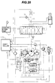
- Fig. 20 is a diagram of a hydraulic circuit including a hydraulic pump control system according to a third embodiment of the present invention.
- Fig. 21 is a flowchart showing general processing procedures of a controller shown in Fig. 20.
- Fig. 22 is a graph showing a characteristic (drive current - command pressure) of a proportional solenoid used in a hydraulic pump control system according to a fourth embodiment of the present invention.
- Fig. 23 is a graph showing a characteristic (command pressure - actual pump tilting) of a regulator used in the hydraulic pump control system of the fourth embodiment.
- Fig. 24 is a flowchart showing processing procedures of a learning control mode according to the fourth embodiment of the present invention.
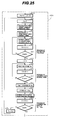
- Fig. 25 is a flowchart showing details of a pump tilting learning calculation process in the procedures shown in Fig. 24.
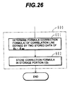
- Fig. 26 is a flowchart showing details of a pump tilting correction formula calculation process in the procedures shown in Fig. 24.
- Fig. 27 is a graph showing a characteristic (target pump tilting - target command pressure) of a target command pressure table stored in a controller.
- Fig. 28 is a graph showing a characteristic (target command pressure - target drive current) of a target drive current table stored in the controller.
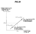
- Fig. 29 is a graph showing a correction formula.
- Fig. 30 is a flowchart showing processing procedures of a normal control mode according to the fourth embodiment of the present invention.
- Fig. 31 is a diagram showing another form of the regulator.
- Fig. 32 is a diagram showing still another form of the regulator.
- Fig. 33 is a diagram of a hydraulic circuit including a flow control valve control system according to the fourth embodiment of the present invention.
- Fig. 34 is a functional block diagram showing an outline of processing procedures of a learning control mode according to the embodiment shown in Fig. 33.
- Fig. 35 is a functional block diagram showing an outline of processing procedures of a normal control mode according to the embodiment shown in Fig. 33.
- a hydraulic circuit according to this embodiment is equipped on a working machine such as a hydraulic excavators and comprises a variable displacement hydraulic pump 1, a reservoir 14, an engine 4 started up upon operation of a start-up switch 20b of a key switch 20 and driving the variable displacement hydraulic pump 1, a hydraulic cylinder 8 driven by a hydraulic fluid delivered from the variable displacement hydraulic pump 1.
- a flow control valve 7 of center bypass type controlling the hydraulic fluid delivered from the variable displacement hydraulic pump 1
- a control lever unit 17 for controlling the flow control valve 7, and a center bypass passage 15 connected to the variable displacement hydraulic pump 1 and the reservoir 14.
- a pump control system of this embodiment is to control the delivery rate of the hydraulic pump 1 and comprises a pilot pump 5, a relief valve 6 for limiting the maximum delivery pressure of the pilot pump 5, a pressure generator, e.g., a throttle 9, disposed in a portion of the center bypass passage 15 between the reservoir 14 and the flow control valve 7 for generating a control pressure (hereinafter referred to as a negative control pressure) Pn corresponding to an input amount by which the control lever unit 17 is operated, a line 16 for introducing the negative control pressure Pn generated by the throttle 9 therethrough, a pressure sensor 10 for detecting the negative control pressure Pn introduced through the line 16 and converting the detected value into an electric signal, a pump tilting angle sensor 11 for detecting a tilting angle (hereinafter referred to as an actual pump tilting) ⁇ of a swash plate 1a of the hydraulic pump 1 and converting the detected value into an electric signal, a revolution speed sensor 18 for detecting a revolution speed Ne of the engine 4 and converting the detected value into an electric signal
- the regulator 2 comprises an actuator 2A for operating the swash plate 1a, a flow control selector valve 2B for controlling the operation of the actuator 2A in accordance with the command pressure P from the proportional solenoid valve 3, and a horsepower control selector valve 2C.
- the actuator 2A comprises a servo piston 2a having pressure bearing areas at opposite ends different from each other and coupled to the swash plate 1a for operating the swash plate 1a, a smaller-diameter side chamber 2b housing therein a smaller-diameter portion of the serve piston 2a, and a larger-diameter side chamber 2c housing therein a larger-diameter portion of the serve piston 2a.
- the flow control selector valve 2B comprises a control spool 2d and a spring 2e disposed at one end of the control spool 2d.
- the command pressure P from the proportional solenoid valve 3 is supplied to the other end of the control spool 2d opposed to the spring 2e.
- the position of the control spool 2d is determined under balance between the command pressure P and the biasing force of the spring 2e.
- the control spool 2d is moved to a right-hand shift position as viewed on the drawing, whereupon the hydraulic fluid from the pilot pump 5 is supplied to both the smaller-diameter side chamber 2b and the larger-diameter side chamber 2c. Therefore, the difference in pressure bearing area between the smaller-diameter side chamber 2b and the larger-diameter side chamber 2c causes the servo piston 2a to move to the left as viewed on the drawing, i.e., in the direction to increase the tilting amount of the swash plate 1a.
- the control spool 2d is moved to a left-hand shift position as viewed on the drawing, whereupon the hydraulic fluid from the pilot pump 5 is supplied to the smaller-diameter side chamber 2b alone, while the larger-diameter side chamber 2c is communicated with the reservoir 14. Therefore, the servo piston 2a is moved to the right as viewed on the drawing, i.e., in the direction to decrease the tilting amount of the swash plate 1a.
- An input/output characteristic of the proportional solenoid valve 3 is shown by "actual characteristic A" in Fig. 2.
- the characteristic A is such that the command pressure P is increased as the drive current I increases. Also, for each of individual proportional solenoid valves, the characteristic A varies within a tolerance of ⁇ ⁇ relative to a target characteristic A0 of the proportional solenoid valve 3.
- a proportional solenoid valve with its actual characteristic A given by the target characteristic A0 outputs a command pressure P 1
- a proportional solenoid valve with its actual characteristic A given by a tolerance upper limit value Au outputs a command pressure P 1u
- a proportional solenoid valve with its actual characteristic A given by a tolerance lower limit value Ad outputs a command pressure P 1d .
- an input/output characteristic of the regulator 2 is also such that the pump tilting ⁇ is increased as the command pressure P increases.
- the characteristic B varies within a tolerance of ⁇ ⁇ (between a tolerance upper limit value Bu and a tolerance lower limit value Bd) relative to a target characteristic B0 of the regulator 2.
- the target characteristic A0 of the proportional solenoid valve 3 and the target characteristic B0 of the regulator 2 are characteristics preset as design values.
- the controller 12 comprises, as shown in Fig. 4, a processing portion 12a, a storage portion 12b, and a proportional solenoid valve driver portion 12c.
- the processing portion 12a carries out a predetermined calculation process based on the negative control pressure Pn, the actual pump tilting ⁇ , the engine revolution speed Ne, and the mode signal Sm.
- the storage portion 12b includes an EPROM in which programs and characteristic data necessary for executing the predetermined calculation process are stored beforehand, a non-volatile memory, e.g., an EEPROM, in which a correction value ⁇ 0 determined in a process of the learning control mode, described later, is stored and data once stored will not be lost even after the power supplied to the controller 12 is cut off, and an RAM in which values produced during the calculation process are stored temporarily.
- the proportional solenoid valve driver portion 12c outputs the drive current I corresponding to the calculation result to the proportional solenoid valve 3.
- Fig. 5 is a graph showing a target pump tilting table used for determining a target pump tilting ⁇ 0 from the negative control pressure Pn.
- the relationship between the negative control pressure Pn and the target pump tilting ⁇ 0 is set such that when the center bypass flow rate is large, the tilting amount of the swash plate 1a of the hydraulic pump 1 is reduced to reduce the pump delivery rate, and when the center bypass flow rate is small, the tilting amount of the swash plate 1a of the hydraulic pump 1 is increased to increase the pump delivery rate.
- Fig. 6 is a graph showing a target command value pressure table used for determining a target command pressure P 0 as a target output of the proportional solenoid valve 3 from the target pump tilting ⁇ 0 .
- the plotted characteristic is a reversal of the target characteristic B0 of the regulator 2 shown in Fig. 3.
- Fig. 7 is a graph showing a target drive current table used for determining a target drive current I 0 as a target input to the proportional solenoid valve 3 from the target command pressure P 0 .
- a characteristic of the plotted table is reversal of the target characteristic A0 of the proportional solenoid valve 3 shown in Fig. 2.
- Fig. 9 is a flowchart showing the general processing procedures of the controller 12.
- the controller when the controller is supplied with power upon the power switch 20a of the key switch 20 being turned on, it reads the mode signal Sm from the mode switch 13 (step 51). This process is executed each time the power switch 20a is turned on. Then, the controller determines whether the mode signal Sm is turned on or not (step 52). If the mode signal Sm is determined being on, the controller executes a process of the learning control mode (step 53), and if the mode signal Sm is determined being off, the controller executes a process of the normal control mode (step 54). In this embodiment, the control flow is designed not to return to the normal control mode until the mode switch 13 is changed over, once switched into the learning control mode. However, the control flow may be designed to return to the normal control mode automatically after the elapse of a certain period of time.
- the controller 12 initially executes a stable engine revolution waiting process 200 in which it waits for that the revolution speed of the engine 4 reaches a prescribed value.
- the learning control is not performed during an inoperative state of the engine 4 before the start-up or an instable state immediately after the start-up, and is performed only when the engine 4 is stabilized at the prescribed revolution speed.
- the controller 12 executes a pump tilting initialization process 300 for minimizing the tilting of the swash plate 1a of the hydraulic pump 1.
- This process 300 is to operate the swash plate 1a of the hydraulic pump 1 from a minimum tilting whenever the swash plate 1a is operated under the learning control, measure the tilting of the hydraulic pump 1 on condition that the effects of plays in the swash plate driving system are constant, and hence prevent the measured value from varying due to the effects of the plays.
- the controller executes a pump tilting learning calculation process 400.
- the controller puts zero (0) in a waiting time counter C1 (step 201) for setting a predetermined time during which it waits for the engine revolution speed being stabilized, e.g., 4 seconds.
- the controller reads the revolution speed Ne of the engine 4 detected by the engine revolution sensor 18 (step 202), and determines whether the engine revolution speed Ne reaches a prescribed value, e.g., a revolution speed within the range of 1350 rpm ⁇ 100 rpm (step 203). If the prescribed revolution speed is not reached, the process of reading the engine revolution speed Ne (step 202) is repeated again.
- a prescribed value e.g., a revolution speed within the range of 1350 rpm ⁇ 100 rpm
- step 204 If the prescribed revolution speed is reached, one (1) is added to the waiting time counter C1 (step 204). It is then determined whether C1 is not less than a set value R1, i.e., 4 seconds in this embodiment (step 205). Unless C1 is not less than 4 seconds, the controller returns to the step 202 of reading the engine revolution speed Ne, thereby repeating the above procedures until C1 becomes not less than 4 seconds. If C1 is not less than 4 seconds, the stable engine revolution waiting process 200 is ended for transition to the pump tilting initialization process 300.
- R1 i.e. 4 seconds
- the controller sets a minimum tilting ⁇ 0min to the target pump tilting ⁇ 0 (step 301). Also, because a certain time is required for that the output of the proportional solenoid valve 3 is transmitted from the regulator 2 to the swash plate 1a and the target pump tilting is established, the controller puts zero (0) in a waiting time counter C2 (step 301) for setting a predetermined time, e.g., 1 second.
- the controller determines whether C4 is not less than a set value R4, i.e., 2 seconds in this embodiment (step 407).
- the actual characteristics of the proportional solenoid valve 3 and the regulator 2 are varied as indicated by A, B shown in Figs. 2 and 3.
- the controller After storing the correction value ⁇ 0 in the RAM of the storage portion 12b, the controller executes a learning calculation value checking process 500 for checking whether the correction value is a properly calculated value.
- the controller reads an actual pump tilting ⁇ a detected by the tilting angle sensor 11 (step 508) and then determines whether the actual pump tilting ⁇ a is within an allowable tilting range of ⁇ 0 - ⁇ x ⁇ ⁇ a ⁇ ⁇ 0 + ⁇ x with respect to the target pump tilting ⁇ 0 (step 509). If the actual pump tilting is within the allowable tilting range, the success of learning is indicated (step 510), and if it is not within the allowable tilting range, the failure of learning is indicated (step 511). Such an indication is practiced by, for example, lighting on an LED (not shown) continuously after the controller enters the above-mentioned learning control flow, lighting off the LED upon the success of learning, and lighting on-and-off the LED upon the failure of learning.
- the controller reads the negative control pressure Pn detected by the pressure sensor 10 (step 81).
- the negative control pressure detected at that time is assumed to be Pn3, for example.
- the proportional solenoid valve 3 Upon the drive current I 3c being output to the proportional solenoid valve 3, the proportional solenoid valve 3 outputs a command pressure P 3c based on the input/output characteristic A shown in Fig. 2, and the regulator 2 moves the swash plate 1a of the hydraulic pump 1 so as to have an actual pump tilting ⁇ 3c based on the input/output characteristic B shown in Fig. 3.
- the correction value ⁇ 0 represents the respective deviations between the actual input/output characteristics A, B and the target input/output characteristics A0, B0 of the proportional solenoid valve 3 and the regulator 2.
- the actual pump tilting ⁇ 3c resulted from controlling the proportional solenoid valve 3 and the regulator 2 with ⁇ 0 + ⁇ 0 set to the target value ( ⁇ 03c ) is the same as the actual pump tilting ⁇ 3 resulted when a target command pressure P 03 is calculated from the target pump tilting ⁇ 03 based on the characteristic shown in Fig. 6, a target drive current I 03 is calculated from the target command pressure P 03 based on the characteristic shown in Fig. 7, a drive current I 3 corresponding to the target drive current I 03 is output to the proportional solenoid valve 3, a command pressure P 3 corresponding to the drive current I 3 is output based on the target characteristic A0 shown in Fig. 2, and the swash plate 1a of the hydraulic pump 1 is moved under the command pressure P 3 based on the target characteristic B0 shown in Fig. 3.
- the actual pump tilting ⁇ c resulted from correcting the target pump tilting ⁇ 0 by addition of the correction value ⁇ 0 is also the same as the actual pump tilting ⁇ resulted through the control based on the target characteristics shown in Figs. 2 and 3 without correcting the target pump tilting ⁇ 0 .
- FIG. 16 An outline of the pump tilting learning calculation process 400 in the learning control mode is shown in a functional block diagram of Fig. 16.
- a block 103 corresponds to the processing function of the step 403 in Fig. 13
- a block 104 corresponds to the processing function of the step 404 in Fig. 13
- a block 105 corresponds to the processing function of the step 405 in Fig. 13.
- the averaged actual pump tilting ⁇ aa is subtracted from the target pump tilting ⁇ 01 in a subtracter 106 to obtain the difference therebetween, i.e., the correction value ⁇ 0 .
- FIG. 17 An outline of the process in the normal control mode is shown in a functional block diagram of Fig. 17.
- a block 111 corresponds to the processing function of the step 82 in Fig. 15
- an adder 112 corresponds to the processing function of the step 83 in Fig. 15
- a block 113 corresponds to the processing function of the step 84 in Fig. 15
- a block 114 corresponds to the processing function of the step 85 in Fig. 15
- a block 115 corresponds to the processing function of the step 86 in Fig. 15.
- a target pump tilting ⁇ 0 corresponding to the negative control pressure Pn is determined and then a value resulted from adding the correction value ⁇ 0 to the target pump tilting ⁇ 01 is set to the target value ⁇ 03c , thereby compensating for the error which would be otherwise caused due to the actual input/output characteristics A, B of the proportional solenoid valve 3 and the regulator 2.
- the proportional solenoid valve 3 and the regulator 2 are controlled.
- the actual pump tilting could be also controlled to be held in agreement with the target pump tilting by using the so-called feedback control in which the tilting angle of the hydraulic pump 1 detected by the tilting angle sensor 11 is fed back to perform control based on a difference between the fed-back data and the target pump tilting.
- the feedback control has the problem that there occurs a response delay and, if the tilting angle sensor 11 should be failed, the control is no longer able to continue.
- the normal control mode is performed under not feedback control, but open loop control without resorting to the value detected by the tilting angle sensor 11, there occurs no response delay and, even if the tilting angle sensor 11 should be failed, the working machine is able to continue the normal operation.
- the learning control mode since one of the learning control mode and the normal control mode is selected by the operator manipulating the mode switch 13, the learning control mode can be selected at the discretion of the operator only when it is required.
- part of the memory included in the storage portion 12b in which the correction value is stored is a non-volatile memory, the value once stored in the memory can be kept even after the power supplied to the controller 12 is cut off, and there is no need of making the learning control frequently.
- FIG. 18 and 19 A second embodiment of the present invention will be described with reference to Figs. 18 and 19.
- the characteristic of the target command pressure table is shifted by an amount corresponding to the correction value ⁇ 0 in the normal control mode.
- Figs. 18 and 19 the same steps and blocks as shown in Figs. 15 and 17 are denoted by the same reference numerals and will not be described below.
- the normal control mode process in this embodiment is the same as in the first embodiment except for steps 83A and 84A.
- the controller reads the correction value ⁇ 0 stored in the EEPROM of the storage portion 12b and shifts the characteristic of the target command pressure table shown in Fig. 6 by an amount corresponding to the correction value ⁇ 0 .
- the controller calculates a target command pressure P 0 corresponding to the target pump tilting ⁇ 0 based on the shifted characteristic of the target command pressure table.
- a block 113A corresponds to the processing function of the step 3A.
- a broken line represents the characteristic of the target command pressure table before the shift and a solid line represents the characteristic of the target command pressure table after having been shifted by an amount corresponding to the correction value ⁇ 0 .
- This embodiment can also reduce variations in the actual pump tilting ⁇ with respect to the target pump tilting ⁇ 0 as with the first embodiment.
- FIG. 20 and 21 A third embodiment of the present invention will be described with reference to Figs. 20 and 21.
- the mode switch 13 is not provided and the learning control mode is executed by using a signal from the start-up switch 20b for the engine 4 of the key switch 20.
- the same members and steps as shown in Figs. 1 and 9 are denoted by the same reference numerals and will not be described below.
- a controller 12A receives a signal Ss from the start-up switch 20b of the key switch 20 (step 51A), determines whether the signal Ss from the start-up switch 20b is turned on or not (step 52A). If the signal Ss is determined being on, the controller executes a process of the learning control mode (step 53). When the process of the learning control mode is ended, the mode is switched to the normal control mode (step 54).
- This embodiment is advantageous in that it is not required for the operator to make specific manipulation to instruct selection of the control mode, and the operation necessary for starting the learning control is simplified.
- a fourth embodiment of the present invention will be described with reference to Figs. 22 and 30. While the target pump tilting is corrected in the above embodiments on an assumption that the input/output characteristics of the proportional solenoid valve and the regulator have the same gradients as the target input/output characteristics, the target pump tilting is corrected in this embodiment, taking into account the case where the characteristics of the proportional solenoid valve and the regulator have gradients different from the gradients of the target characteristics. Because the system configuration of this embodiment is the same as of the first embodiment, the following description will be made by using the reference numerals shown in Fig. 1 with the system configuration not illustrated in the drawings.
- Fig. 22 shows an input/output characteristic of the proportional solenoid valve 3 supposed in this embodiment.
- An actual characteristic A varies for each of individual proportional solenoid valves within a tolerance of ⁇ ⁇ relative to a target characteristic A0, and have the same gradient as the target characteristic A0 in some cases and a gradient different therefrom in other cases.
- Fig. 23 shows an input/output characteristic of the regulator 2 supposed in this embodiment.
- An actual characteristic B also varies for each of individual regulators within a tolerance of ⁇ ⁇ relative to a target characteristic B0, and have the same gradient as the target characteristic B0 in some cases and a gradient different therefrom in other cases.
- this embodiment is designed to determine a difference between the target pump tilting and the actual pump tilting in at least two points through the learning calculation process in the learning control mode, determine a correction formula from the differences determined in the two points for estimating respective deviations between the actual input/output characteristics A, B and the target input/output characteristics A0, B0 of the proportional solenoid valve 3 and the regulator 2, and determine a correction value in the normal control mode by using the correction formula, thereby correcting the target pump tilting.
- the general processing procedures of the controller 12 are the same as in the first embodiment shown in Fig. 9.
- the learning control mode or the normal control mode is selectively started depending on whether the mode switch Sm is on or off.
- the controller 12 initially executes a stable engine revolution waiting process 100 and then a pump tilting initialization process 300.
- the procedures of these two processes are the same as shown in Figs. 11 and 12 relating to the first embodiment.
- the controller executes a pump tilting learning calculation process 400A and thereafter a pump tilting correction formula calculation process 600.
- the controller first sets a predetermined tilting ⁇ 01 to the target pump tilting ⁇ 0 and puts zero (0) in a number-of-execution-cycles counter C3 for setting the number of times R3, i.e., 2 in this embodiment, that the following steps from 402 to 416 are repeated (step 401A). Also, because a certain time is required for that the output of the proportional solenoid valve 3 is transmitted from the regulator 2 to the swash plate 1a and the target pump tilting is established, the controller puts zero (0) in a waiting time counter C4 (step 402) for setting a predetermined time, e.g., 2 seconds.
- the actual characteristics of the proportional solenoid valve 3 and the regulator 2 are varied as indicated by A, B shown in Figs. 22 and 23.
- the learning calculation value checking process 500 is the same as in the first embodiment shown in Fig. 14.
- the controller adds one (1) to the number-of-execution-cycles counter C3 (step 414) and then determines whether C3 is not less than the set number of times R3 (2) (step 415). Unless C3 is not less than the number of times R3 (2), the controller sets a predetermined tilting ⁇ 02 different from ⁇ 01 to the target pump tilting ⁇ 0 and then returns to the step 402 of putting zero (0) in the waiting time counter C4, thereby repeating the above steps 403 to 415.
- step 601 KX + C
- the controller reads the negative control pressure Pn detected by the pressure sensor 10 (step 81).
- the negative control pressure detected at that time is assumed to be Pn3, for example.
- the proportional solenoid valve 3 Upon the drive current I 3c being output to the proportional solenoid valve 3, the proportional solenoid valve 3 outputs a command pressure P 3c based on the input/output characteristic A shown in Fig. 22, and the regulator 2 moves the swash plate 1a of the hydraulic pump 1 so as to have an actual pump tilting ⁇ 3c based on the input/output characteristic B shown in Fig. 23.
- the actual pump tilting ⁇ 3c resulted from controlling the proportional solenoid valve 3 and the regulator 2 with ⁇ 0 + ⁇ 0 set to the target value ( ⁇ 03c ) is the same as the actual pump tilting ⁇ 3 resulted when a target command pressure P 03 is calculated from the target pump tilting ⁇ 03 based on the characteristic shown in Fig. 27, a target drive current I 03 is calculated from the target command pressure P 03 based on the characteristic shown in Fig. 28, a drive current I 3 corresponding to the target drive current I 03 is output to the proportional solenoid valve 3, a command pressure P 3 corresponding to the drive current I 3 is output based on the target characteristic A0 shown in Fig. 22, and the swash plate 1a of the hydraulic pump 1 is moved under the command pressure P 3 based on the target characteristic B0 shown in Fig. 23.
- the actual pump tilting ⁇ c resulted from deriving the tilting correction value ⁇ 0 from the correction formula and correcting the target pump tilting ⁇ 0 by addition of the correction value ⁇ 0 is also the same as the actual pump tilting ⁇ resulted through the control based on the target characteristics shown in Figs. 22 and 23 without correcting the target pump tilting ⁇ 0 .
- displacement control means for the variable displacement hydraulic pump 1 as an object to be controlled by the controller 12 is a combination of the proportional solenoid valve 3 and the regulator 2.
- the present invention is not limited to the foregoing embodiments, and the displacement control means may be a combination of high-speed solenoid valves 30a, 30b and the regulator 2 as shown in Fig. 31.
- the high-speed solenoid valve 30a when the high-speed solenoid valve 30a is held in a closed state and the high-speed solenoid valve 30b is switched to an open state in response to a drive current I from the controller 12, the communication between the smaller-diameter side chamber 2b and the larger-diameter side chamber 2c is cut off, the larger-diameter side chamber 2c is communicated with the reservoir, and the hydraulic fluid from the variable displacement hydraulic pump 1 is supplied to the smaller-diameter side chamber 2b alone, thus causing the servo piston 2a to move to the right as viewed on the drawing.
- the swash plate 1a is operated to control the displacement of the variable displacement hydraulic pump 1.
- the displacement control means for the variable displacement hydraulic pump 1 may comprise a proportional solenoid 31 as shown in Fig. 32.
- the controller outputs a drive current I corresponding to the target pump tilting ⁇ 0 , and the proportional solenoid 31 generates an electromagnetic force in proportion to the drive current I.
- a spool (not shown) is moved in accordance with the electromagnetic force, and the swash plate 1a is moved in accordance with the movement of the spool to control the displacement of the variable displacement hydraulic pump 1.
- FIG. 33 illustrates, as another example of the control object other than the displacement control means for the hydraulic pump, a proportional solenoid valve for outputting a command pilot pressures to the flow control valve.
- Fig. 33 the same members as shown in Fig. 1 are denoted by the same reference numerals.
- 17A denoted by 17A is an electric lever unit.
- An input signal (electric signal) from the electric lever unit 17A is input to a controller 12B.
- the controller 12B outputs drive currents to proportional solenoid valves 40, 41 as control objects, whereupon the proportional solenoid valves 40, 41 are driven by the drive currents to produce command pressures.
- the flow control valve 7 is operated under the command pressures to control the flow rate of the hydraulic fluid supplied to the hydraulic actuator 8. Further, the command pressures produced by the proportional solenoid valves 40, 41 are detected by pressure sensors 42, 43, respectively, and electric signals corresponding to the detected values are input to the controller 12B.
- the characteristic of the target drive current table is reversal of the target input/output characteristic of the proportional solenoid valve 40.
- a command pressure P produced by the proportional solenoid valve 40 is detected by the pressure sensor 42.
- a drive current I B is output to the proportional solenoid valve 41 and a correction value ⁇ P B0 is provided.
- the correction values ⁇ P A0 , ⁇ P B0 represent respective deviations between the actual input/output characteristics and the target input/output characteristics of the proportional solenoid valves 40, 41.
- FIG. 35 An outline of a process in the normal control mode is shown in a functional block diagram of Fig. 35.
- target command pressures P 0 corresponding to an input signal X 0 from the electric lever unit 17A at that time are calculated based on the characteristics of target command pressure tables depending on the direction in which the flow control valve 7 is operated.
- adders 132A and 132B the foregoing correction values ⁇ P A0 , ⁇ P B0 are added to the respective target command pressures P 0 to derive corrected target command pressures.
- the errors of actual command pressures which would be caused if the drive currents I A , I B are output by using the target command pressures P 0 (P 01 ) as they are without any correction, are offset in advance.
- target drive currents I 0 corresponding to the corrected target command pressures P 0 are calculated based on the characteristics of target drive current tables.
- the characteristics of the target drive current table are also reversal of the target input/output characteristic of the proportional solenoid valves 40, 41.
- drive currents I A , I B corresponding to the target drive currents I 0 are determined and then output to the proportional solenoid valves 40, 41, respectively.
- the output of each control object can be controlled to be always equal to a target value and variations in the output can be reduced. Also, since normal control is performed under open loop control, there occurs no response delay and, even if sensors or the like should be failed, working machines are able to continue the normal operation.
- an actual pump tilting as an output of the displacement control means can be controlled to be always equal to a target pump tilting and variations in the actual pump tilting can be reduced. It is therefore possible to improve the fine operability and a feeling in the operation of hydraulic working machines, and increase the working efficiency thereof.
Landscapes
- Engineering & Computer Science (AREA)
- General Engineering & Computer Science (AREA)
- Mining & Mineral Resources (AREA)
- Civil Engineering (AREA)
- Structural Engineering (AREA)
- Physics & Mathematics (AREA)
- Automation & Control Theory (AREA)
- General Physics & Mathematics (AREA)
- Mechanical Engineering (AREA)
- Artificial Intelligence (AREA)
- Medical Informatics (AREA)
- Software Systems (AREA)
- Evolutionary Computation (AREA)
- Computer Vision & Pattern Recognition (AREA)
- Health & Medical Sciences (AREA)
- Computer Hardware Design (AREA)
- Fluid Mechanics (AREA)
- Control Of Positive-Displacement Pumps (AREA)
- Fluid-Pressure Circuits (AREA)
- Operation Control Of Excavators (AREA)
- Feedback Control In General (AREA)
Applications Claiming Priority (4)
| Application Number | Priority Date | Filing Date | Title |
|---|---|---|---|
| JP33059995 | 1995-12-19 | ||
| JP33059995A JP3497031B2 (ja) | 1995-03-07 | 1995-12-19 | 油圧ポンプ制御装置 |
| JP330599/95 | 1995-12-19 | ||
| PCT/JP1996/002517 WO1997022914A1 (en) | 1995-12-19 | 1996-09-05 | Method of output correction for control apparatus, the control apparatus, and hydraulic pump control apparatus |
Publications (3)
| Publication Number | Publication Date |
|---|---|
| EP0810497A1 true EP0810497A1 (de) | 1997-12-03 |
| EP0810497A4 EP0810497A4 (de) | 1998-05-20 |
| EP0810497B1 EP0810497B1 (de) | 2002-12-18 |
Family
ID=18234463
Family Applications (1)
| Application Number | Title | Priority Date | Filing Date |
|---|---|---|---|
| EP96929531A Expired - Lifetime EP0810497B1 (de) | 1995-12-19 | 1996-09-05 | Verfahren zur korrektur des ausgangsignals eines steuergerätes, steuergerät und steuergerät für hydraulikpumpe |
Country Status (5)
| Country | Link |
|---|---|
| EP (1) | EP0810497B1 (de) |
| KR (1) | KR100225422B1 (de) |
| CN (1) | CN1137417C (de) |
| DE (1) | DE69625469T2 (de) |
| WO (1) | WO1997022914A1 (de) |
Cited By (5)
| Publication number | Priority date | Publication date | Assignee | Title |
|---|---|---|---|---|
| EP0922813A3 (de) * | 1997-12-04 | 2000-04-12 | Hitachi Construction Machinery Co., Ltd. | Hydraulisches Betätigungssystem für ein hydraulisches Arbeitsfahrzeug |
| EP1306552A3 (de) * | 2001-10-26 | 2005-06-08 | Caterpillar Inc. | Elektrohydraulische Pumpensteuervorrichtung |
| WO2010075216A3 (en) * | 2008-12-23 | 2010-10-14 | Caterpillar Inc. | Hydraulic control system having flow force compensation |
| EP2551524A1 (de) * | 2011-07-29 | 2013-01-30 | Poclain Hydraulics Industrie | Hydraulischer Steuerschaltkreis |
| EP2796623A4 (de) * | 2011-12-21 | 2015-11-11 | Volvo Constr Equip Ab | Vorrichtung zur einstellung des steuerbarkeitsgrades für baumaschinen |
Families Citing this family (14)
| Publication number | Priority date | Publication date | Assignee | Title |
|---|---|---|---|---|
| KR100507485B1 (ko) * | 2003-05-27 | 2005-08-17 | 현대자동차주식회사 | 자동 변속기의 솔레노이드 플런저 보정 제어장치 및 방법 |
| JP4042057B2 (ja) * | 2003-11-04 | 2008-02-06 | 株式会社デンソー | バルブ開度調整装置およびコモンレール式燃料噴射装置 |
| GB0502149D0 (en) * | 2005-02-02 | 2005-03-09 | Boc Group Inc | Method of operating a pumping system |
| JP4353190B2 (ja) * | 2006-02-27 | 2009-10-28 | コベルコ建機株式会社 | 建設機械の油圧回路 |
| DE102011115896B4 (de) * | 2011-10-14 | 2015-05-28 | Bürkert Werke GmbH | Vorrichtung und Verfahren zur Prozessregelung |
| CN102493523B (zh) * | 2011-11-25 | 2013-12-04 | 徐州徐工挖掘机械有限公司 | 一种新型挖掘机限流控制系统 |
| CN102518168B (zh) * | 2011-12-08 | 2015-04-08 | 上海三一重机有限公司 | 液压系统控制装置及其控制方法及包括该装置的挖掘机 |
| CN103306329B (zh) * | 2013-05-28 | 2016-04-13 | 上海三一重机有限公司 | 一种基于挖掘机的液压剪微控控制系统及方法及挖掘机 |
| CN109689979B (zh) * | 2017-03-07 | 2021-05-18 | 日立建机株式会社 | 工程机械 |
| JP6885812B2 (ja) * | 2017-07-12 | 2021-06-16 | 株式会社山田製作所 | 油圧制御装置及び油圧制御方法 |
| JP6966830B2 (ja) * | 2018-04-27 | 2021-11-17 | キャタピラー エス エー アール エル | 可変容量型油圧ポンプの較正システム |
| JP7141894B2 (ja) * | 2018-09-05 | 2022-09-26 | 日立建機株式会社 | 作業機械 |
| JP6947711B2 (ja) * | 2018-09-28 | 2021-10-13 | 日立建機株式会社 | 建設機械 |
| CN118775239B (zh) * | 2024-09-05 | 2024-12-24 | 浩宸建设科技股份有限公司 | 一种水利工程建筑设备的高精度控制方法及系统 |
Family Cites Families (16)
| Publication number | Priority date | Publication date | Assignee | Title |
|---|---|---|---|---|
| US3845288A (en) * | 1971-06-28 | 1974-10-29 | Trw Inc | Data normalizing method and system |
| FR2512977A1 (fr) * | 1981-09-11 | 1983-03-18 | Thomson Csf | Dispositif a servovalve electrohydraulique |
| CA1184273A (en) * | 1982-09-23 | 1985-03-19 | Kazuyoshi Yasukawa | Robot control apparatus |
| JPH0648219Y2 (ja) * | 1985-03-29 | 1994-12-12 | 新キャタピラ−三菱株式会社 | 建設機械用電気・油圧比例制御弁の制御装置 |
| JPS6248990A (ja) * | 1985-08-26 | 1987-03-03 | Toyota Motor Corp | 容積式回転圧縮送風機の体積効率測定方法 |
| JPH074765B2 (ja) * | 1986-03-03 | 1995-01-25 | 長尾 高明 | 曲面加工装置 |
| US4920305A (en) * | 1987-06-12 | 1990-04-24 | The Babcock & Wilcox Company | Auto calibrating electro hydraulic servo driver |
| JPH02231602A (ja) * | 1989-03-06 | 1990-09-13 | Yaskawa Electric Mfg Co Ltd | 汎用学習制御装置 |
| US5065695A (en) * | 1989-06-16 | 1991-11-19 | Nordson Corporation | Apparatus for compensating for non-linear flow characteristics in dispensing a coating material |
| US5126933A (en) * | 1990-02-07 | 1992-06-30 | White Iii Charles A | Self-learning memory unit for process controller and self-updating function generator |
| US5315976A (en) * | 1990-03-17 | 1994-05-31 | Robert Bosch Gmbh | Error-corrected closed-loop control system |
| JPH04220701A (ja) * | 1990-12-21 | 1992-08-11 | Tokimec Inc | 流体制御システム |
| JP2919128B2 (ja) * | 1991-09-02 | 1999-07-12 | 東洋機械金属株式会社 | 射出成形機の比例電磁制御弁の制御方法 |
| JP3230826B2 (ja) * | 1991-10-16 | 2001-11-19 | ファナック株式会社 | スポット溶接ガンの位置補正方法及びロボット溶接装置 |
| JPH05265509A (ja) * | 1992-03-16 | 1993-10-15 | Mitsubishi Heavy Ind Ltd | 学習制御装置 |
| KR0152300B1 (ko) * | 1993-07-02 | 1998-10-15 | 김연수 | 유압펌프의 토출유량 제어방법 |
-
1996
- 1996-09-05 CN CNB961910313A patent/CN1137417C/zh not_active Expired - Fee Related
- 1996-09-05 KR KR1019970703021A patent/KR100225422B1/ko not_active Expired - Fee Related
- 1996-09-05 DE DE69625469T patent/DE69625469T2/de not_active Expired - Lifetime
- 1996-09-05 WO PCT/JP1996/002517 patent/WO1997022914A1/ja not_active Ceased
- 1996-09-05 EP EP96929531A patent/EP0810497B1/de not_active Expired - Lifetime
Cited By (9)
| Publication number | Priority date | Publication date | Assignee | Title |
|---|---|---|---|---|
| EP0922813A3 (de) * | 1997-12-04 | 2000-04-12 | Hitachi Construction Machinery Co., Ltd. | Hydraulisches Betätigungssystem für ein hydraulisches Arbeitsfahrzeug |
| EP1306552A3 (de) * | 2001-10-26 | 2005-06-08 | Caterpillar Inc. | Elektrohydraulische Pumpensteuervorrichtung |
| WO2010075216A3 (en) * | 2008-12-23 | 2010-10-14 | Caterpillar Inc. | Hydraulic control system having flow force compensation |
| US8511080B2 (en) | 2008-12-23 | 2013-08-20 | Caterpillar Inc. | Hydraulic control system having flow force compensation |
| DE112009003826B4 (de) * | 2008-12-23 | 2015-12-31 | Caterpillar Inc. | Hydrauliksteuerungssystem mit Strömungskraftkompensation |
| EP2551524A1 (de) * | 2011-07-29 | 2013-01-30 | Poclain Hydraulics Industrie | Hydraulischer Steuerschaltkreis |
| FR2978506A1 (fr) * | 2011-07-29 | 2013-02-01 | Poclain Hydraulics Ind | Circuit de commande hydraulique |
| FR2986579A1 (fr) * | 2011-07-29 | 2013-08-09 | Poclain Hydraulics Ind | Circuit de commande hydraulique |
| EP2796623A4 (de) * | 2011-12-21 | 2015-11-11 | Volvo Constr Equip Ab | Vorrichtung zur einstellung des steuerbarkeitsgrades für baumaschinen |
Also Published As
| Publication number | Publication date |
|---|---|
| KR100225422B1 (ko) | 1999-10-15 |
| DE69625469D1 (de) | 2003-01-30 |
| EP0810497A4 (de) | 1998-05-20 |
| KR970707391A (ko) | 1997-12-01 |
| CN1165570A (zh) | 1997-11-19 |
| EP0810497B1 (de) | 2002-12-18 |
| DE69625469T2 (de) | 2003-10-02 |
| WO1997022914A1 (en) | 1997-06-26 |
| CN1137417C (zh) | 2004-02-04 |
Similar Documents
| Publication | Publication Date | Title |
|---|---|---|
| US6101456A (en) | Output correcting method in control system, control system, and hydraulic pump control system | |
| EP0810497B1 (de) | Verfahren zur korrektur des ausgangsignals eines steuergerätes, steuergerät und steuergerät für hydraulikpumpe | |
| KR950007624B1 (ko) | 유압펌프의 제어장치 | |
| US5535587A (en) | Hydraulic drive system | |
| KR930009513B1 (ko) | 건설기계의 유압구동장치 | |
| US4967557A (en) | Control system for load-sensing hydraulic drive circuit | |
| EP0884422B1 (de) | Motorsteuereinrichtung für eine Baumaschine | |
| JP3510114B2 (ja) | 作業機の制御方法およびその制御装置 | |
| US11920325B2 (en) | Construction machine | |
| KR920007650B1 (ko) | 작업기계의 유압회로장치 | |
| EP4290021A1 (de) | Arbeitsmaschine | |
| US11149410B2 (en) | Work machine with automatic and manual operating control | |
| JP2651079B2 (ja) | 油圧建設機械 | |
| US11421715B2 (en) | Hydraulic control circuit for working machine | |
| US5245828A (en) | Hydraulic drive system for civil engineering and construction machine | |
| JP2920057B2 (ja) | 建設機械の油圧制御装置 | |
| US12276087B2 (en) | Work machine | |
| JP2001182719A (ja) | 流体圧回路における負荷圧力推定方法およびその装置 | |
| JP3113547B2 (ja) | 油圧制御回路 | |
| EP4610438A1 (de) | Arbeitsmaschine und aktuatorkalibrierungssystem | |
| JPH09229004A (ja) | 油圧駆動機械の制御装置 | |
| KR950008534B1 (ko) | 건설기계의 제어방법과 장치 | |
| JP2846949B2 (ja) | 作業機械の油圧回路装置 | |
| JP2001184130A (ja) | 圧力制御方法および圧力制御装置 | |
| JPH07111180B2 (ja) | ロードセンシング油圧駆動装置 |
Legal Events
| Date | Code | Title | Description |
|---|---|---|---|
| PUAI | Public reference made under article 153(3) epc to a published international application that has entered the european phase |
Free format text: ORIGINAL CODE: 0009012 |
|
| 17P | Request for examination filed |
Effective date: 19970911 |
|
| AK | Designated contracting states |
Kind code of ref document: A1 Designated state(s): DE GB IT |
|
| A4 | Supplementary search report drawn up and despatched | ||
| AK | Designated contracting states |
Kind code of ref document: A4 Designated state(s): DE GB IT |
|
| 17Q | First examination report despatched |
Effective date: 20001121 |
|
| GRAG | Despatch of communication of intention to grant |
Free format text: ORIGINAL CODE: EPIDOS AGRA |
|
| GRAG | Despatch of communication of intention to grant |
Free format text: ORIGINAL CODE: EPIDOS AGRA |
|
| GRAH | Despatch of communication of intention to grant a patent |
Free format text: ORIGINAL CODE: EPIDOS IGRA |
|
| GRAH | Despatch of communication of intention to grant a patent |
Free format text: ORIGINAL CODE: EPIDOS IGRA |
|
| GRAH | Despatch of communication of intention to grant a patent |
Free format text: ORIGINAL CODE: EPIDOS IGRA |
|
| RAP1 | Party data changed (applicant data changed or rights of an application transferred) |
Owner name: HITACHI CONSTRUCTION MACHINERY CO., LTD. |
|
| GRAA | (expected) grant |
Free format text: ORIGINAL CODE: 0009210 |
|
| AK | Designated contracting states |
Kind code of ref document: B1 Designated state(s): DE GB IT |
|
| REG | Reference to a national code |
Ref country code: GB Ref legal event code: FG4D |
|
| REF | Corresponds to: |
Ref document number: 69625469 Country of ref document: DE Date of ref document: 20030130 Kind code of ref document: P Ref document number: 69625469 Country of ref document: DE Date of ref document: 20030130 |
|
| PLBE | No opposition filed within time limit |
Free format text: ORIGINAL CODE: 0009261 |
|
| STAA | Information on the status of an ep patent application or granted ep patent |
Free format text: STATUS: NO OPPOSITION FILED WITHIN TIME LIMIT |
|
| 26N | No opposition filed |
Effective date: 20030919 |
|
| PGFP | Annual fee paid to national office [announced via postgrant information from national office to epo] |
Ref country code: GB Payment date: 20090902 Year of fee payment: 14 |
|
| PGFP | Annual fee paid to national office [announced via postgrant information from national office to epo] |
Ref country code: DE Payment date: 20090903 Year of fee payment: 14 |
|
| PGFP | Annual fee paid to national office [announced via postgrant information from national office to epo] |
Ref country code: IT Payment date: 20090912 Year of fee payment: 14 |
|
| GBPC | Gb: european patent ceased through non-payment of renewal fee |
Effective date: 20100905 |
|
| PG25 | Lapsed in a contracting state [announced via postgrant information from national office to epo] |
Ref country code: IT Free format text: LAPSE BECAUSE OF NON-PAYMENT OF DUE FEES Effective date: 20100905 |
|
| REG | Reference to a national code |
Ref country code: DE Ref legal event code: R119 Ref document number: 69625469 Country of ref document: DE Effective date: 20110401 |
|
| PG25 | Lapsed in a contracting state [announced via postgrant information from national office to epo] |
Ref country code: DE Free format text: LAPSE BECAUSE OF NON-PAYMENT OF DUE FEES Effective date: 20110401 |
|
| PG25 | Lapsed in a contracting state [announced via postgrant information from national office to epo] |
Ref country code: GB Free format text: LAPSE BECAUSE OF NON-PAYMENT OF DUE FEES Effective date: 20100905 |