EP0810594A2 - Magnetooptischer Aufzeichnungsträger - Google Patents
Magnetooptischer Aufzeichnungsträger Download PDFInfo
- Publication number
- EP0810594A2 EP0810594A2 EP97303570A EP97303570A EP0810594A2 EP 0810594 A2 EP0810594 A2 EP 0810594A2 EP 97303570 A EP97303570 A EP 97303570A EP 97303570 A EP97303570 A EP 97303570A EP 0810594 A2 EP0810594 A2 EP 0810594A2
- Authority
- EP
- European Patent Office
- Prior art keywords
- layer
- magneto
- recording medium
- reproducing
- optical recording
- Prior art date
- Legal status (The legal status is an assumption and is not a legal conclusion. Google has not performed a legal analysis and makes no representation as to the accuracy of the status listed.)
- Granted
Links
- 230000005415 magnetization Effects 0.000 claims abstract description 260
- 229910045601 alloy Inorganic materials 0.000 claims description 39
- 239000000956 alloy Substances 0.000 claims description 39
- 230000008878 coupling Effects 0.000 claims description 26
- 238000010168 coupling process Methods 0.000 claims description 26
- 238000005859 coupling reaction Methods 0.000 claims description 26
- 229910052751 metal Inorganic materials 0.000 claims description 18
- 239000002184 metal Substances 0.000 claims description 16
- 230000007704 transition Effects 0.000 claims description 12
- 239000000203 mixture Substances 0.000 claims description 11
- 230000004907 flux Effects 0.000 claims description 10
- 230000002829 reductive effect Effects 0.000 abstract description 6
- 230000005381 magnetic domain Effects 0.000 abstract description 4
- 239000010410 layer Substances 0.000 description 416
- 239000010408 film Substances 0.000 description 94
- 230000000052 comparative effect Effects 0.000 description 28
- 230000000873 masking effect Effects 0.000 description 17
- 239000007789 gas Substances 0.000 description 13
- 239000000463 material Substances 0.000 description 13
- XKRFYHLGVUSROY-UHFFFAOYSA-N Argon Chemical compound [Ar] XKRFYHLGVUSROY-UHFFFAOYSA-N 0.000 description 12
- 229910052723 transition metal Inorganic materials 0.000 description 12
- 230000000694 effects Effects 0.000 description 10
- 238000004519 manufacturing process Methods 0.000 description 10
- 230000003287 optical effect Effects 0.000 description 9
- 239000011241 protective layer Substances 0.000 description 9
- 239000000758 substrate Substances 0.000 description 9
- 238000009826 distribution Methods 0.000 description 8
- 230000007423 decrease Effects 0.000 description 7
- 150000002739 metals Chemical class 0.000 description 7
- 229910052761 rare earth metal Inorganic materials 0.000 description 7
- 150000002910 rare earth metals Chemical class 0.000 description 7
- 150000003624 transition metals Chemical class 0.000 description 7
- IJGRMHOSHXDMSA-UHFFFAOYSA-N Atomic nitrogen Chemical compound N#N IJGRMHOSHXDMSA-UHFFFAOYSA-N 0.000 description 6
- 229910052786 argon Inorganic materials 0.000 description 6
- 238000005259 measurement Methods 0.000 description 5
- 238000004544 sputter deposition Methods 0.000 description 5
- 229910052715 tantalum Inorganic materials 0.000 description 5
- 229910052719 titanium Inorganic materials 0.000 description 5
- 229910052802 copper Inorganic materials 0.000 description 4
- 229910052737 gold Inorganic materials 0.000 description 4
- 102100032047 Alsin Human genes 0.000 description 3
- 101710187109 Alsin Proteins 0.000 description 3
- 230000003247 decreasing effect Effects 0.000 description 3
- 229910052757 nitrogen Inorganic materials 0.000 description 3
- 229910052697 platinum Inorganic materials 0.000 description 3
- 230000001105 regulatory effect Effects 0.000 description 3
- 239000011347 resin Substances 0.000 description 3
- 229920005989 resin Polymers 0.000 description 3
- 230000004304 visual acuity Effects 0.000 description 3
- 229910052692 Dysprosium Inorganic materials 0.000 description 2
- 229910052771 Terbium Inorganic materials 0.000 description 2
- QVGXLLKOCUKJST-UHFFFAOYSA-N atomic oxygen Chemical compound [O] QVGXLLKOCUKJST-UHFFFAOYSA-N 0.000 description 2
- 239000003989 dielectric material Substances 0.000 description 2
- 230000006870 function Effects 0.000 description 2
- 239000001301 oxygen Substances 0.000 description 2
- 229910052760 oxygen Inorganic materials 0.000 description 2
- 229920000515 polycarbonate Polymers 0.000 description 2
- 239000004417 polycarbonate Substances 0.000 description 2
- 230000004044 response Effects 0.000 description 2
- 239000004065 semiconductor Substances 0.000 description 2
- 229910052710 silicon Inorganic materials 0.000 description 2
- 238000004528 spin coating Methods 0.000 description 2
- 230000003313 weakening effect Effects 0.000 description 2
- -1 AlN Chemical compound 0.000 description 1
- 229910052688 Gadolinium Inorganic materials 0.000 description 1
- 230000005374 Kerr effect Effects 0.000 description 1
- 229910052779 Neodymium Inorganic materials 0.000 description 1
- 230000008901 benefit Effects 0.000 description 1
- 230000008859 change Effects 0.000 description 1
- 238000002425 crystallisation Methods 0.000 description 1
- 230000008025 crystallization Effects 0.000 description 1
- 230000002542 deteriorative effect Effects 0.000 description 1
- 229910052742 iron Inorganic materials 0.000 description 1
- 229910001092 metal group alloy Inorganic materials 0.000 description 1
- 238000000034 method Methods 0.000 description 1
- 230000004048 modification Effects 0.000 description 1
- 238000012986 modification Methods 0.000 description 1
- 229910052759 nickel Inorganic materials 0.000 description 1
- 230000003647 oxidation Effects 0.000 description 1
- 238000007254 oxidation reaction Methods 0.000 description 1
- 230000010287 polarization Effects 0.000 description 1
- 230000008569 process Effects 0.000 description 1
- 230000001681 protective effect Effects 0.000 description 1
- 230000001603 reducing effect Effects 0.000 description 1
- 230000002787 reinforcement Effects 0.000 description 1
- 230000002441 reversible effect Effects 0.000 description 1
- 238000005728 strengthening Methods 0.000 description 1
- 230000008719 thickening Effects 0.000 description 1
- 239000010409 thin film Substances 0.000 description 1
- 239000012780 transparent material Substances 0.000 description 1
Images



Classifications
-
- G—PHYSICS
- G11—INFORMATION STORAGE
- G11B—INFORMATION STORAGE BASED ON RELATIVE MOVEMENT BETWEEN RECORD CARRIER AND TRANSDUCER
- G11B7/00—Recording or reproducing by optical means, e.g. recording using a thermal beam of optical radiation by modifying optical properties or the physical structure, reproducing using an optical beam at lower power by sensing optical properties; Record carriers therefor
- G11B7/24—Record carriers characterised by shape, structure or physical properties, or by the selection of the material
- G11B7/2403—Layers; Shape, structure or physical properties thereof
-
- G—PHYSICS
- G11—INFORMATION STORAGE
- G11B—INFORMATION STORAGE BASED ON RELATIVE MOVEMENT BETWEEN RECORD CARRIER AND TRANSDUCER
- G11B11/00—Recording on or reproducing from the same record carrier wherein for these two operations the methods are covered by different main groups of groups G11B3/00 - G11B7/00 or by different subgroups of group G11B9/00; Record carriers therefor
- G11B11/10—Recording on or reproducing from the same record carrier wherein for these two operations the methods are covered by different main groups of groups G11B3/00 - G11B7/00 or by different subgroups of group G11B9/00; Record carriers therefor using recording by magnetic means or other means for magnetisation or demagnetisation of a record carrier, e.g. light induced spin magnetisation; Demagnetisation by thermal or stress means in the presence or not of an orienting magnetic field
- G11B11/105—Recording on or reproducing from the same record carrier wherein for these two operations the methods are covered by different main groups of groups G11B3/00 - G11B7/00 or by different subgroups of group G11B9/00; Record carriers therefor using recording by magnetic means or other means for magnetisation or demagnetisation of a record carrier, e.g. light induced spin magnetisation; Demagnetisation by thermal or stress means in the presence or not of an orienting magnetic field using a beam of light or a magnetic field for recording by change of magnetisation and a beam of light for reproducing, i.e. magneto-optical, e.g. light-induced thermomagnetic recording, spin magnetisation recording, Kerr or Faraday effect reproducing
- G11B11/10582—Record carriers characterised by the selection of the material or by the structure or form
- G11B11/10586—Record carriers characterised by the selection of the material or by the structure or form characterised by the selection of the material
-
- G—PHYSICS
- G11—INFORMATION STORAGE
- G11B—INFORMATION STORAGE BASED ON RELATIVE MOVEMENT BETWEEN RECORD CARRIER AND TRANSDUCER
- G11B11/00—Recording on or reproducing from the same record carrier wherein for these two operations the methods are covered by different main groups of groups G11B3/00 - G11B7/00 or by different subgroups of group G11B9/00; Record carriers therefor
- G11B11/10—Recording on or reproducing from the same record carrier wherein for these two operations the methods are covered by different main groups of groups G11B3/00 - G11B7/00 or by different subgroups of group G11B9/00; Record carriers therefor using recording by magnetic means or other means for magnetisation or demagnetisation of a record carrier, e.g. light induced spin magnetisation; Demagnetisation by thermal or stress means in the presence or not of an orienting magnetic field
- G11B11/105—Recording on or reproducing from the same record carrier wherein for these two operations the methods are covered by different main groups of groups G11B3/00 - G11B7/00 or by different subgroups of group G11B9/00; Record carriers therefor using recording by magnetic means or other means for magnetisation or demagnetisation of a record carrier, e.g. light induced spin magnetisation; Demagnetisation by thermal or stress means in the presence or not of an orienting magnetic field using a beam of light or a magnetic field for recording by change of magnetisation and a beam of light for reproducing, i.e. magneto-optical, e.g. light-induced thermomagnetic recording, spin magnetisation recording, Kerr or Faraday effect reproducing
-
- Y—GENERAL TAGGING OF NEW TECHNOLOGICAL DEVELOPMENTS; GENERAL TAGGING OF CROSS-SECTIONAL TECHNOLOGIES SPANNING OVER SEVERAL SECTIONS OF THE IPC; TECHNICAL SUBJECTS COVERED BY FORMER USPC CROSS-REFERENCE ART COLLECTIONS [XRACs] AND DIGESTS
- Y10—TECHNICAL SUBJECTS COVERED BY FORMER USPC
- Y10S—TECHNICAL SUBJECTS COVERED BY FORMER USPC CROSS-REFERENCE ART COLLECTIONS [XRACs] AND DIGESTS
- Y10S428/00—Stock material or miscellaneous articles
- Y10S428/90—Magnetic feature
-
- Y—GENERAL TAGGING OF NEW TECHNOLOGICAL DEVELOPMENTS; GENERAL TAGGING OF CROSS-SECTIONAL TECHNOLOGIES SPANNING OVER SEVERAL SECTIONS OF THE IPC; TECHNICAL SUBJECTS COVERED BY FORMER USPC CROSS-REFERENCE ART COLLECTIONS [XRACs] AND DIGESTS
- Y10—TECHNICAL SUBJECTS COVERED BY FORMER USPC
- Y10T—TECHNICAL SUBJECTS COVERED BY FORMER US CLASSIFICATION
- Y10T428/00—Stock material or miscellaneous articles
- Y10T428/26—Web or sheet containing structurally defined element or component, the element or component having a specified physical dimension
-
- Y—GENERAL TAGGING OF NEW TECHNOLOGICAL DEVELOPMENTS; GENERAL TAGGING OF CROSS-SECTIONAL TECHNOLOGIES SPANNING OVER SEVERAL SECTIONS OF THE IPC; TECHNICAL SUBJECTS COVERED BY FORMER USPC CROSS-REFERENCE ART COLLECTIONS [XRACs] AND DIGESTS
- Y10—TECHNICAL SUBJECTS COVERED BY FORMER USPC
- Y10T—TECHNICAL SUBJECTS COVERED BY FORMER US CLASSIFICATION
- Y10T428/00—Stock material or miscellaneous articles
- Y10T428/26—Web or sheet containing structurally defined element or component, the element or component having a specified physical dimension
- Y10T428/263—Coating layer not in excess of 5 mils thick or equivalent
- Y10T428/264—Up to 3 mils
- Y10T428/265—1 mil or less
Definitions
- the present invention relates to a magneto-optical recording medium for use in a magneto-optical recording and reproducing apparatus, such as a magneto-optical disk, a magneto-optical tape, a magneto-optical card, etc.
- a magneto-optical recording medium has been widely used as a rewritable magneto-optical recording medium.
- information is recorded and reproduced by converging a light beam from a semiconductor laser onto the magneto-optical recording medium.
- magneto-optical recording medium has a drawback in that when a recording bit diameter and an interval between the recording bits are smaller with respect to a diameter of the light beam, reproducing characteristics deteriorate. The described problem occurs for the following reason. As the adjoining recording bits fall within the diameter of spot of the laser beam on the target recording bit, it is not possible to reproduce each recording bit separately.
- Japanese Unexamined Patent Publication No. 150418/1994 discloses a magneto-optical recording medium including a reproducing layer which has in-plane magnetization at room temperature and in which a transition from the in-plane magnetization to perpendicular magnetization occurs with a temperature rise, a recording layer having perpendicular magnetization for recording information, and a non-magnetic intermediate layer formed between the reproducing layer and the recording layer wherein the reproducing layer and the recording layer are magnetostatically coupled.
- the magneto-optical recording medium disclosed in the above-mentioned Japanese Unexamined Patent Publication No. 150418/1994 have such drawback that in the case where recording and reproducing are carried out on a magneto-optical recording medium having a smaller recording bit diameter and an smaller interval between the recording bits, it is not possible to obtain reproducing signal as a result of insufficient masking of the reproducing layer having the in-plane magnetization.
- the magneto-optical recording medium of the present invention is characterized by including a reproducing layer which has in-plane magnetization at room temperature and in which a transition occurs from the in-plane magnetization to perpendicular magnetization at a temperature of not less than a critical temperature, a recording layer for recording information magneto-optically, the recording layer being made of a perpendicular magnetization film, an intermediate layer formed between the reproducing layer and the recording layer, the intermediate layer being made of a non-magnetic film, and an in-plane magnetization layer in which magnetization reduces at a temperature in a vicinity of the critical temperature, the in-plane magnetization is formed adjacent to at least one side of the reproducing layer.
- in-plane magnetization layer and the reproducing layer are exchange-coupled at a temperature of not more than the critical temperature, in-plane magnetization masking of the reproducing layer for the recording layer is emphasized. Therefore, even when recording and reproducing are carried out on a magneto-optical recording medium having a smaller recording bit diameter and a smaller interval between the recording bits, a sufficient reproducing signal can be obtained, namely, magnetic superresolution reproducing is achieved.
- the intermediate layer completely cuts off (1) the exchange coupling between the reproducing layer and the recording layer, and (2) the exchange coupling between the in-plane magnetization layer and the recording layer, thereby achieving a desirable magnetostatic coupling between (1) the reproducing layer and the recording layer, and (2) the in-plane magnetization layer and the recording layer.
- Fig. 1 is an explanatory view explaining a reproducing principle of a magneto-optical recording medium of the present invention.
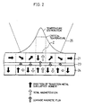
- Fig. 2 is an explanatory view explaining a reproducing principle of a conventional magneto-optical recording medium.
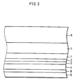
- Fig. 3 is an explanatory view showing the schematic structure of a magneto-optical disk of the present invention.
- Fig. 4 is a graph showing a mark length dependency of CNR of the magneto-optical disk as defined in Fig. 3.
- Fig. 5 is an explanatory view showing the schematic structure of another magneto-optical disk of the present invention.
- Fig. 6 is an explanatory view showing the schematic structure of still another magneto-optical disk of the present invention.
- Fig. 1 is an explanatory view showing a principle of a superresolution reproducing operation of the magneto-optical recording medium of the present invention.
- Fig. 2 is an explanatory view showing a principle of a superresolution reproducing operation of a conventional magneto-optical recording medium.
- the conventional superresolution magneto-optical reproducing medium is arranged so as to include a non-magnetic intermediate layer 23 formed between a reproducing layer 21, made of an alloy of a rare earth metal and a transition metal which has in-plane magnetization at room temperature while a transition from the in-plane magnetization to perpendicular magnetization occurs at a temperature of not less than a critical temperature, and a recording layer 24 made of an alloy of a rare earth metal and a transition metal having a compensation temperature at room temperature where the reproducing layer 21 and the recording layer 24 are magnetostatically coupled.
- Reproducing is carried out by projecting and converging a light beam 25 from the side of the reproducing layer 21.
- a temperature distribution in the form of a Guassian distribution is formed on the medium according to the distribution of light intensity of the light beam 25.
- a transition from the in-plane magnetization to the perpendicular magnetization occurs in the reproducing layer 21.
- a portion Z has a temperature of not less than the critical temperature and therefore has the perpendicular magnetization.
- the total magnetization in the portion Z of the reproducing layer 21 is arranged in the direction of the leakage magnetic flux generated from the recording layer 24.
- the magneto-optical recording medium of the present invention desirably, information is reproduced only from the portion having a temperature of not less than the critical temperature in which the perpendicular magnetization is exhibited.
- the magnetization in the reproducing layer 21 is inclined with respect to the film surface by an effect of the leakage magnetic flux generated from the total magnetization in the recording layer 24.
- the region in a vicinity of the portion Z contains perpendicular magnetization components subjected to reproducing.
- the reproducing layer 21 in order to achieve such characteristics that the in-plane magnetization is exhibited at room temperature, and a transition occurs therein from the in-plane magnetization to the perpendicular magnetization as temperature rises, with respect to a compensation composition, in which rare earth metal sub-lattice moment and transition metal sub-lattice moment balance with each other, it is required to have a larger amount of the rare earth metal sub-lattice moment so that the direction of the transition metal sub-lattice moment and the direction of the total magnetization in the reproducing layer 21 are anti-parallel to each other.
- the recording layer 24 including a rare earth-transition metal alloy having a compensation temperature at room temperature, the intensity of the transition metal sub-lattice moment becomes stronger than that of the rare earth metal sub-lattice moment in the process of a temperature rise. As a result, the transition metal sub-lattice moment and the total magnetization in the recording layer 24 are parallel to each other.
- an in-plane magnetization layer 2 is formed adjacent to the reproducing layer 1.
- the in-plane magnetization layer 2 is designed so as not to have magnetization at a temperature of not less than the critical temperature or so as to have a lower intensity of the magnetization at around the critical temperature as temperature rises.
- the reproducing layer 1 and the in-plane magnetization layer 2 are adjacent to each other, the in-plane magnetization in the in-plane magnetization layer 2 and the in-plane magnetization in the reproducing layer 1 are exchange-coupled at a temperature of not more than the critical-temperature. Therefore, the magnetization direction in the reproducing layer 1 is arranged exactly in an in-plane direction.
- the intensity of the magnetization in the in-plane magnetization layer 2 is lowered or the magnetization disappears therefrom with a temperature rise induced by the temperature distribution.
- a transition from the in-plane magnetization to the perpendicular magnetization occurs in the reproducing layer 1 as temperature rises. Consequently, an exchange coupling force exerted between the in-plane magnetization layer 2 and the reproducing layer 1 weakens.
- the reproducing layer 1 has the perpendicular magnetization at a temperature of not less than the critical temperature.
- the direction of the total magnetization in the portion Z is arranged in the direction of the leakage magnetic flux generated from the recording layer 4.
- the in-plane magnetization in the in-plane magnetization layer 2 and the in-plane magnetization in the reproducing layer 1 are exchange-coupled at a temperature of not more than the critical temperature, the in-plane magnetization is maintained in the reproducing layer 1.
- the intensity of the magnetization in the in-plane magnetization layer 2 is lowered, and the exchange coupling force is lowered.
- the reproducing layer 1 has the perpendicular magnetization.
- the magneto-optical disk in accordance with the present embodiment is composed of a disk main body including a substrate 6, a transparent dielectric layer 7, a reproducing layer 1, an in-plane magnetization layer 2, a non-magnetic intermediate layer 3, a recording layer 4, a protective layer 8, and an overcoat layer 9 which are laminated in this order.
- the described magneto-optical disk adopts a recording system based on a Curie temperature. Namely, a light beam 5 projected from a semiconductor laser is converged onto a reproducing layer 1 by an objective lens, and information recording and reproducing operations are performed by utilizing the magneto-optical effect known as the polar Kerr effect, i.e., a polarization plane of reflected light rotates in a reverse direction according to the magnetization direction in the magnetic layer having a magnetization in a direction perpendicular to the light incident surface.
- the polar Kerr effect i.e., a polarization plane of reflected light rotates in a reverse direction according to the magnetization direction in the magnetic layer having a magnetization in a direction perpendicular to the light incident surface.
- the substrate 6 formed in a disk shape is made of a transparent material such as polycarbonate.
- the transparent dielectric layer 7 is made of materials which do not include oxygen, such as AlN, SiN, AlSiN, etc., and has a film thickness to realize a desired interference effect and increase an angle of the Kerr rotation of the medium.
- the thickness of the film is set approximately to ( ⁇ /4n).
- the film thickness of the transparent dielectric layer 7 is set approximately in a range of 40 nm and 100 nm.
- the reproducing layer 1 is a magnetic film made of a rare earth-transition metal alloy, and its composition is adjusted so as to have such magnetic characteristics that the reproducing layer 1 has in-plane magnetization at room temperature while a transition from the in-plane magnetization to the perpendicular magnetization occurs with a temperature rise.
- the in-plane magnetization layer 2 is made of a magnetic film including the following alloy or metals as a main component: rare earth-transition metal alloy, a rare earth metal, or a transition metal, and the in-plane magnetization layer 2 has magnetization in a direction parallel to the film surface.
- the composition of the in-plane magnetization layer 2 is adjusted so that the in-plane magnetization is maintained in the reproducing layer 1 at a temperature of not more than the critical temperature so that the intensity of the magnetization at a temperature above the critical temperature is lowered to allow leakage magnetic flux, generated from the recording layer 4 in response to the weakening of the magnetization at a temperature of not less than the critical temperature, to transmit.
- the non-magnetic intermediate layer 3 is made of dielectrics such as AlN, SiN, and AlSiN, etc., or an alloy composed of a non-magnetic metal such as Al, Ti, and Ta, etc.
- the non-magnetic intermediate layer 3 has a film thickness in a range of 1 nm and 40 nm in order to magnetostatically couple (1) the reproducing layer 1 and the recording layer, and (2) the in-plane magnetization layer 2 and the recording layer 4.
- the recording layer 4 is a perpendicular magnetic film made of the rare earth-transition metal alloy, and the film is set to a thickness in a range of 20 nm and 80 nm.
- the protective layer 8 which is made of dielectrics such as AlN, SiN, and AlSiN, etc., or an alloy composed of a non-magnetic metal such as Al, Ti, and Ta, etc., is formed in order to prevent the oxidation of the rare earth-transition metal used in the reproducing layer 1 or the recording layer 4.
- the film is set to a thickness in a range of 5 nm and 60 nm in order to realize a desirable protective thin film for preventing oxygen from passing through.
- the overcoat layer 9 is formed on the protective layer 8 by applying an ultraviolet ray hardening resin or a thermal hardening resin by spin-coating. Then, an irradiation of the ultraviolet ray or an application of heat is carried out.
- the following describes the method of manufacturing the magneto-optical disk having the above-mentioned arrangement.
- the substrate 6 formed in a disk shape made of polycarbonate having formed thereon pregroove and prepit is placed on a substrate holder inside the sputtering device provided with a target of Al, a GdFeCo alloy, a GdFeAl alloy, and a GdDyFeCo alloy and air is exhausted from the sputtering device to 1 x 10 -6 Torr, and a mixed gas of argon and nitrogen is introduced therein, and an electric power is supplied to the Al target, and under the gas pressure of 4 x 10 -3 Torr, the transparent dielectric film 7 made of AlN having a film thickness of 80 nm is formed on the substrate 6.
- the reproducing layer 1 made of Gd 0.30 (Fe 0.80 Co 0.20 ) 0.70 having a film thickness of 40 nm is formed on the transparent dielectric layer 7.
- the reproducing layer 1 has such characteristics that the in-plane magnetization is exhibited at room temperature, and a transition occurs therein from the in-plane magnetization to the perpendicular magnetization at 120 °C with the compensation temperature and the Curie temperature of 300 °C and 320 °C respectively.
- the in-plane magnetization layer 2 is an in-plane magnetization layer with a Curie temperature of 120 °C having magnetization in a direction parallel to the film surface at temperatures ranging from room temperature to the Curie temperature (120 °C).
- the non-magnetic intermediate layer 3 made of AlN having a film thickness of 4 nm is formed on the in-plane magnetization layer 2 by introducing a mixed gas of argon and nitrogen under the gas pressure of 4 ⁇ 10 -3 Torr.
- the recording layer 4 made of (Gd 0.50 Dy 0.50 ) 0.23 (Fe 0.30 Co 0.20 ) 0.77 having a film thickness of 40 nm is formed on the non-magnetic intermediate layer 3.
- the compensation temperature and a Curie temperature of the recording layer 4 are 25 °C and 275 °C respectively.
- the protective layer 8 made of AlN having a film thickness of 20 nm is formed on the recording layer 4.
- the overcoat layer 9 is formed on the protective layer 8 by applying an ultraviolet ray hardening resin by spin-coating. Then, an irradiation of the ultraviolet ray is carried out.
- the CNR (carrier to noise ratio) of the above-mentioned magneto-optical disk is measured by the optical pickup using a semiconductive laser having a wavelength of 680 nm.
- Fig. 4 shows a mark length dependency of the CNR (carrier to noise ratio).
- the mark length dependency of the CNR (carrier to noise ratio) of a magneto-optical disk without the in-plane magnetization layer 2 is also shown in the Fig. 4 as a comparative example 1.
- the arrangement of the magneto-optical disk without the in-plane magnetization layer 2 has the same arranaement of the magneto-optical disk of the present embodiment from which the in-plane magnetization layer 2 is excluded.
- the mark length dependency of the CNR indicates the carrier to noise ratio at the time of sequentially forming a recording magnetic domain having a length corresponding to the mark length by a recording magnetic domain pitch having twice the length of the mark length.
- the magneto-optical disk of the present embodiment includes the in-plane magnetization layer 2 formed adjacent to the reproducing layer 1, and the magnetization in the in-plane magnetization layer 2 decreases around the critical temperature of the reproducing layer 1. Therefore, such problem that the magnetization direction in the reproducing layer 1 is inclined with respect to the film surface at a temperature of not more than the critical temperature is prevented, thereby improving the resolving power in reproducing.
- Table 1 shows the result of a measurement of the CNR at the mark length of 0.3 ⁇ m in which the film thicknesses of the reproducing layer 1 and the in-plane magnetization layer 2 are varied.
- Thickness of Reproducing Layer nm
- Thickness of inplane Magnetization Layer nm
- CNR dB
- 40 0* 34.0 40 2 35.0 40 5 37.5 40 10 38.5 40 20 39.5 40 40 35.5 40 60 33.5 8 20 32.5 10 20 34.5 20 20 36.5 30 20 38.5 40 20 39.5 60 20 36.5 80 20 36.5 120 20 33.5 *
- the second row indicates the result where a magneto-optical recording medium without the in-plane magnetization layer is used.
- the film thickness of 0 nm under the column of the thickness of in-plane magnetization layer indicates the result of the conventional magneto-optical recording medium (hereinafter referred to as comparative example 1) without the in-plane magnetization layer.
- the CNR has an increment of 1 dB compared with the result of the comparative example 1. This results from strengthening of the in-plane magnetization masking at a temperature of not more than the critical temperature of the reproducing layer 1. Further, as the film thickness of the in-plane magnetization layer 2 is increased, the CNR also increases until the film thickness reaches 20 nm, and the CNR decreases for the film thicknesses thicker than 20 nm, and becomes smaller than that of the comparative example 1 when the film thickness is 60 nm.
- a film thickness of the in-plane magnetization layer 2 is preferably in a range of 2 nm and 40 nm.
- Table 1 also shows that in the case where the film thickness of the reproducing layer 1 is 8 nm, the CNR becomes lower than that of the comparative example 1 as the reproducing signal diminishes. Further, in the case where the film thickness of the reproducing layer 1 is 120 nm, the CNR becomes lower than that of the comparative example 1 for a reason that a complete perpendicular magnetization in a portion where the temperature has risen not less than the critical temperature is prevented as a result of an increase in an energy of a magnetic wall generated in the reproducing layer 1. Therefore, as it can be seen in Table 1, a film thickness of the reproducing layer 1 in a range of 10 nm and 80 nm is preferred in order to obtain CNR higher than that of the comparative example 1.
- Table 2 shows results of measurements of the CNR and the intensity of magnetic field required for erasing (erasing magnetic field) at the mark length of 0.3 ⁇ m as the film thickness of the non-magnetic intermediate layer 3 is varied.
- the CNR becomes considerably low when the film thickness of the non-magnetic intermediate layer 3 is 0.5 nm. It is assumed that this problem is caused by undesirable coupling due to the non-magnetic intermediate layer 3 being too thin.
- Table 2 also shows that CNR is maximized when the film thickness of the non-magnetic intermediate layer 3 is 1 nm, and the CNR decreases with an increase in the film thickness of the non-magnetic intermediate layer 3 as the magnetostatic coupling force becomes weaker. Therefore, it is required to set the film thickness of the non-magnetic intermediate layer 3 in a range of 1 nm and 80 nm in order to obtain a higher CNR than that of the comparative example 1.
- the magnetostatic coupling force is decreased by thickening the film of the non-magnetic intermediate layer 3. This lowers the intensity of the erasing magnetic field. Therefore, it is preferable that the non-magnetic intermediate layer 3 has a film thickness of not less than 4 nm in order to make the erasing magnetic field to have a value of not more than 31 kA/m that has a practical use.
- Table 3 shows a Curie temperature T c2 and the CNR at the mark length of 0.3 ⁇ m measured by an optical pickup using a semiconductive laser having a wavelength of 680 nm by changing the value of X (atom ratio) in the in-plane magnetization layer 2 made of (Gd 0.11 Fe 0.89 ) x Al 1-x having a film thickness of 20 nm.
- Table 3 shows that CNR that are higher than the CNR (34.0 dB) of the comparative example 1 in which the in-plane magnetization layer 2 is not formed is obtained when X falls in a range of 0.30 ⁇ X ⁇ 1.00.
- the reproducing layer 1 has the perpendicular magnetization at 120 °C. Therefore, since the in-plane magnetization layer 2 is required to emphasize the in-plane magnetization masking only at a temperature of not more than 120 °C, the optimum value of the Curie temperature of the in-plane magnetization layer 2 is set to 120 °C.
- CNR that is higher than the CNR obtained in the comparative example 1 is also obtained at the Curie temperature of the in-plane magnetization layer in a range of not less than 60 °C and not more than 220 °C. Therefore, the in-plane magnetization masking of the reproducing layer 1 can be emphasized to some degree by using a material which lowers its magnetization as temperature rises to around the critical temperature, instead of using a material in which magnetization becomes zero at the critical temperature at which the reproducing layer 1 has the perpendicular magnetization.
- GdFeAl is used as an in-plane magnetization layer 2
- other materials also can be used, provided that the material has a Curie temperature in a range of 60 °C and 220 °C.
- an in-plane magnetization layer 2 made of GdFe, NdFe, NdFeAl, DyFe, and DyFeAl can be used.
- Gd 0.11 Fe 0.89 0.75 Z 0.25 (Z is a metal element other than Al) is used as the in-plane magnetization layer 2.
- Table 4 shows a Curie temperature T c2 of the above-mentioned in-plane magnetization layer 2 and the CNR at the mark length of 0.3 ⁇ m measured by an optical pickup using a semiconductive laser having a wavelength of 680 nm.
- Ti, Ta, Pt, Au, Cu, Al 0.5 Ti 0.5 , and Al 0.5 Ta 0.5 may be used for Z, and for comparison, the CNR of the magneto-optical disk without the in-plane magnetization layer is shown in the afore-mentioned comparative example 1 (Table 1).
- rare earth metals that can be used as materials for the in-plane magnetization layer 2 include Tb and Dy, etc.
- the reproducing layer 1 is made of Gd 0.30 (Fe 0.80 Co 0.20 ) 0.70 having a film thickness of 40 nm
- the in-plane magnetization layer 2 is made of (Gd 0.11 Fe 0.89 ) 0.75 Al 0.25 having a film thickness of 20 nm
- the non-magnetic intermediate layer 3 is made of AlN having a film thickness of 4 nm
- the recording layer 4 is made of (Gd 0.50 Dy 0.50 ) 0.23 (Fe 0.80 Co 0.20 ) 0.77 having a film thickness of 40 nm with varying the values of 1 a film thickness of the reproducing layer 1 and the in-plane magnetization layer 2, 2 a film thickness of the non-magnetic intermediate layer 3, and 3 materials and compositions of the in-plane magnetization layer 2.
- the reproducing layer 1, the in-plane magnetization layer 2, the non-magnetic intermediate layer 3, and the recording layer 4 respectively have a film thickness in a range of not less than 10 nm and not more than 80 nm, not less than 2 nm and not more than 40 nm, and not less than 1 nm and not more than 80 nm.
- the magneto-optical disk in accordance with the present embodiment is composed of a disk main body including a substrate 6, a transparent dielectric layer 7, an in-plane magnetization layer 2, a reproducing layer 1, a non-magnetic intermediate layer 3, a recording layer 4, a protective layer 8, and an overcoat layer 9 which are laminated in this order.
- the magneto-optical disk of the present embodiment has an arrangement where the order of forming the reproducing layer 1 and the in-plane magnetization layer 2 is reversed from that of the magneto-optical disk of the first embodiment.
- the magneto-optical disk of the present embodiment can be manufactured by reversing the order of forming the reproducing layer 1 and the in-plane magnetization layer 2 in accordance with the method of manufacturing the magneto-optical disk as defined in the first embodiment. In this manner, a magneto-optical disk composed of the substrate 6, the transparent dielectric layer 7, the in-plane magnetization layer 2, the reproducing layer 1, the non-magnetic intermediate layer 3, the recording layer 4, the protective layer 8, and the overcoat layer 9 is manufactured.
- Table 5 shows CNR at the mark length of 0.3 ⁇ m measured by the optical pickup using a semiconductive laser having a wavelength of 680 nm as a film thickness of the reproducing layer 1 and a film thickness of the in-plane magnetization layer 2 are varied.
- Thickness of Reproducing Layer nm
- Thickness of inplane Magnetization Layer nm
- CNR dB
- 40 0* 34.0 40 2 34.5 40 4 35.0 40 6 37.0 40 8 37.0 40 10 34.5 40 12 32.5 10 6 31.0 15 6 34.5 20 6 35.5 30 6 37.5 40 6 37.0 50 6 36.5 60 6 35.5 70 6 33.5 *
- the second row indicates the result where a magneto-optical recording medium without the in-plane magnetization layer is used.
- the film thickness of 0 nm under the column of the thickness of in-plane magnetization layer indicates the result of the conventional magneto-optical recording medium (comparative example 1) without the in-plane magnetization layer.
- the CNR is relatively low since the in-plane magnetization layer 2 is positioned at the light incident side of the light beam 5. Consequently, a range of a film thickness of the reproducing layer 1 for achieving CNR which are higher than that of the comparative example 1 is reduced. Consequently, it is required to set a film thickness of the reproducing layer 1 to have a film thickness in a range of 15 nm and 60 nm.
- the reproducing layer 1 is made of Gd 0.30 (Fe 0.80 Co 0.20 ) 0.70
- the in-plane magnetization layer 2 is made of (Gd 0.11 Fe 0.89 ) 0.75 Al 0.25
- the non-magnetic intermediate layer 3 is made of AlN
- the recording layer 4 is made of (Gd 0.50 Dy 0.50 ) 0.23 (Fe 0.80 Co 0.20 ) 0.77 with varying film thicknesses of the reproducing layer 1 and the in-plane magnetization layer 2.
- the reproducing layer 1 and the in-plane magnetization layer 2 respectively have a film thickness in a range of not less than 15 nm and not more than 60 nm, and not less than 2 nm and not more than 10 nm.
- the non-magnetic intermediate layer 3 has the same condition as that in the first embodiment, namely, a film thickness in a range of not less than 1 nm and not more than 80 nm is preferred.
- the magneto-optical disk in accordance with the present embodiment is composed of a disk main body including a substrate 6, a transparent dielectric layer 7, a reproducing layer 1, an in-plane magnetization layer 2, a non-magnetic intermediate layer 3, a reflecting layer 10, a recording layer 4, a protective layer 8, and an overcoat layer 9 which are laminated in this order.
- the magneto-optical disks adopted in the first and second embodiments in the case where a total film thickness of the reproducing layer 1 and the in-plane magnetization layer 2 is less than 40 nm, it is possible that information recorded on the recording layer 4 is mingled in the reproducing layer 1 as the light beam 5 having passed through the reproducing layer 1 and the in-plane magnetization layer 2 is reflected by the recording layer 4. In case of such event, the mask effect due to the in-plane magnetization in the reproducing layer 1 and the in-plane magnetization in the in-plane magnetization layer 2 is decreased.
- the magneto-optical disk of the present embodiment having the arrangement of the magneto-optical disk of the first embodiment further includes the reflective layer 10 formed between the non-magnetic intermediate layer 3 and the recording layer 4.
- the light beam 5 having passed through the reproducing layer 1 and the in-plane magnetization layer 2 is reflected by the reflective layer 10, thereby preventing the information recorded on the recording layer 4 from entering the reproducing signal, and achieving a mask effect of the in-plane magnetization in the reproducing layer 1 and the in-plane magnetization in the in-plane magnetization layer 2.
- the method of manufacturing the magneto-optical disk of the present embodiment differs from the manufacturing method of the first embodiment in that the reflective layer 10 made of Al is formed between the non-magnetic intermediate layer 3 and the recording layer 4.
- the substrate 6, the transparent dielectric layer 7, the reproducing layer 1, the in-plane magnetization layer 2, the non-magnetic intermediate layer 3, the recording layer 4, the protective layer 8, and the overcoat layer 9 are formed in the same manner as that of the first embodiment where the film thickness of the reproducing layer 1 and the in-plane magnetization layer 2 is set to 17.5 nm and 7.5 nm respectively.
- the non-magnetic intermediate layer 3 air is exhausted again from the sputtering device to 1 ⁇ 10 -6 Torr, and argon gas is introduced therein, and an electric power is supplied to the Al target. Then, under the gas pressure of 4 ⁇ 10 -3 Torr, the reflective layer 10 having a film thickness of 2 nm to 80 nm is formed on the non-magnetic intermediate layer 3.
- Table 6 shows CNR at the mark length of 0.3 ⁇ m measured by an optical pickup using a semiconductive laser having a wavelength of 680 nm as a film thickness of the reflective layer 10 is varied.
- Thickness of Reflective Layer (nm) CNR (dB) 0* 35.5 2 36.0 5 37.5 10 38.0 20 40.5 30 39.0 40 37.0 50 33.5 * The second row indicates the result where a magneto-optical recording medium without the reflective layer is used. (comparative example 2)
- the film thickness of 0 nm under the column of the thickness of the reflective layer indicates a result of the measurement where the conventional magneto-optical recording medium (comparative example 2) without the reflective layer 10 is used.
- the CNR decreases when the film thickness is not less than 20 mm.
- a film thickness of the reflective layer 10 needs to be set to a range of 2 nm to 40 nm in order to obtain a higher CNR than that of the comparative example 2.
- Table 7 shows CNR at the mark length of 0.3 ⁇ m measured by the optical pickup using a semiconductive laser having a wavelength of 680 nm and the intensity of the erasing magnetic field as values of X (atom ratio) are varied in the reflective layer 10 made of Al 1-x Fe x having a film thickness of 20 nm.
- X (atom ratio) CNR (dB) Erasing Magnetic Field (KA/m) 0 40.5 50 0.02 40.5 17 0.05 40.5 16 0.10 40.5 17 0.25 40.0 18 0.50 39.5 30 0.60 38.5 58
- the erasing magnetic field As can be seen in Table 7, as the Fe content increases, in other words, as the X becomes larger than 0.10, the CNR gradually decreases. Despite this, all the CNR are higher than that of the comparative example 2, thereby showing the effect of forming the reflective layer 10.
- the erasing magnetic field the erasing magnetic field of high intensity, i.e., 50 kA/m is required in the case of adopting the reflective layer 10 made of pure A1 is used, whereas the erasing magnetic field can be decreased by setting the X to a value in a range of not less than 0.02 and not more than 0.50.
- Table 8 shows CNR at the mark length of 0.3 ⁇ m measured by an optical pickup using a semiconductive laser having a wavelength of 680 nm and an intensity of the erasing magnetic field as values of X (atom ratio) are varied in the reflective layer 10 made of Al 1-x Ni x having a film thickness of 20 nm.
- X (atom ratio) CNR (dB) Erasing Magnetic Field (kA/m) 0 40.5 50 0.02 40.5 15 0.05 40.0 16 0.10 40.0 18 0.25 39.5 18 0.50 39.0 28 0.60 38.0 62
- the erasing magnetic field can be reduced by setting the X to a value in a range of not less than 0.02 and not more than 0.50.
- the erasing magnetic field also can be reduced in the same manner by adding magnetic metals such as Co, Gd, Tb, Dy, and Nd, etc., to Al instead of Fe and Ni.
- Table 9 shows CNR at the mark length of 0.3 ⁇ m measured by the optical pickup using a semiconductive laser having a wavelength of 680 nm and an intensity of the erasing magnetic field as values of X (atom ratio) are varied with respect to the reflective layer 10 made of Al 1-x Ti x having a film thickness of 20 nm.
- X (atom ratio) CNR (dB) Erasing Magnetic Field (kA/m) 0 40.5 50 0.02 40.5 15 0.05 40.0 16 0.10 40.0 18 0.25 40.5 17 0.50 40.0 15 0.75 39.5 17 0.90 40.0 16 0.95 39.5 17 0.98 39.0 15 1.00 38.0 48
- the erasing magnetic field As is clear from Table 9, as the Ti content increases, in other words, as the X becomes larger than 0.10, the CNR gradually decreases. Despite this, all the CNR are higher than that of the comparative example 2, thereby showing the effect of forming the reflective layer 10.
- the erasing magnetic field the erasing magnetic field of high intensity, i.e., 50 kA/m is required in the case where the reflective layer 10 made of pure Al is used, whereas the erasing magnetic field can be made smaller by setting the value for X in a range of not less than 0.02 and not more than 0.98.
- Table 10 shows erasing magnetic field reducing effects in the case where non-magnetic metal elements other than Ti are added to Al as the reflective layer 10, and CNR at the mark length of 0.3 ⁇ m measured by the optical pickup using a semiconductive laser having a wavelength of 680 nm and an intensity of the erasing magnetic field in the case where non-magnetic metals excluding Ti are used as Z with respect to the reflective layer 10 made of Al 0.5 Z 0.5 .
- the erasing magnetic field is reduced by adding a magnetic metal and a non-magnetic metal to Al. This is because by adding magnetic metals and non-magnetic metals, crystallization of Al at the time of forming the reflective layer 10 can be prevented, thereby improving a magnetic characteristics of the recording layer 4 formed thereon.
- examples of a material for the reflective layer that can be used alone such as Al or as an alloy in combination with other element include Ti, Ta, Pt, Au, Cu, Si, etc.
- the first magneto-optical recording medium of the present invention is characterized by including a reproducing layer which has in-plane magnetization at room temperature and in which a transition occurs from the in-plane magnetization to perpendicular magnetization at a temperature of not less than a critical temperature, a recording layer for recording information magneto-optically, the recording layer being made of a perpendicular magnetization film, an intermediate layer formed between the reproducing layer and the recording layer, the intermediate layer being made of a non-magnetic film, and an in-plane magnetization layer in which magnetization reduces at a temperature in a vicinity of the critical temperature, the in-plane magnetization is formed adjacent to at least one side of the reproducing layer.
- the in-plane magnetization layer and the reproducing layer are magnetostatically coupled at a temperature of not more than the critical temperature, the magnetization direction in the reproducing layer does not incline with respect to the film surface, and an in-plane magnetization masking of the reproducing layer for the recording layer is emphasized. Therefore, even in the case where recording and reproducing are carried out on a magneto-optical recording medium having a smaller recording bit diameter and a smaller interval between the recording bits, a sufficient recording signal can be obtained, namely, magnetic superresolution reproducing is achieved.
- the non-magnetic intermediate layer completely cuts off (1) the exchange coupling exerted between the reproducing layer and the reproducing layer, and (2) the exchange coupling exerted between the in-plane magnetization layer and the recording layer, thereby achieving a desirable magnetostatic coupling between (1) the reproducing layer and the recording layer, and (2) the in-plane magnetization layer and the recording layer.
- the second magneto-optical recording medium of the present invention having the same arrangement as the above-mentioned first magneto-optical recording medium of the present invention is characterized in that the magnetization in the in-plane magnetization layer disappears at a temperature around the critical temperature.
- the magnetization in the in-plane magnetization layer disappears at a temperature around the critical temperature, the magnetization direction in the reproducing layer is not regulated by the in-plane magnetization layer, thereby permitting transferring of the leakage magnetic flux from the recording layer to the reproducing layer with ease.
- the third magneto-optical recording medium of the present invention having the arrangement of the first magneto-optical recording medium of the present invention is characterized in that the in-plane magnetization layer eliminates exchange coupling with the reproducing layer to allow the leakage magnetic flux to be transferred from the recording layer to the reproducing layer.
- the in-plane magnetization layer and the reproducing layer are magnetostatically coupled at a temperature of not more than the critical temperature, an in-plane magnetization masking of the reproducing layer is emphasized.
- the leakage magnetic flux is transferred from the recording layer to the reproducing layer. Therefore, even when recording and reproducing are carried out on a magneto-optical recording medium having a smaller recording bit diameter and a smaller interval between the recording bits, a sufficient recording signal can be obtained, namely, magnetic superresolution reproducing is achieved.
- the fourth magneto-optical recording medium of the present invention having the same arrangement as the above-mentioned first magneto-optical recording medium of the present invention is characterized in that the Curie temperature of the in-plane magnetization layer is substantially the same as the critical temperature.
- the magnetization in the in-plane magnetization layer disappears. Therefore, at a temperature of not more than the critical temperature, the reproducing layer and the in-plane magnetization layer are magnetostatically coupled, and the magnetization direction in the reproducing layer is regulated by the in-plane magnetization layer. On the other hand, at a temperature of not less than the critical temperature, the magnetization direction in the reproducing layer is not regulated by the in-plane magnetization layer since the magnetization in the in-plane magnetization layer disappears, and the reproducing layer has the perpendicular magnetization as a result.
- the magnetization direction in the reproducing layer does not incline with respect to the film surface, and the in-plane magnetization masking is emphasized. Moreover, at a temperature of not less than the critical temperature, the leakage magnetic flux from the recording layer is transferred to the reproducing layer with ease.
- the fifth magneto-optical recording medium of the present invention having the same arrangement as the above-mentioned first magneto-optical recording medium of the present invention is characterized in that the in-plane magnetization layer is composed an alloy selected from the group consisting of: a GdFe alloy, a GdFeAl alloy, a GdFeTi alloy, a GdFeTa alloy, a GdFePt alloy, a GdfeAu alloy, a GdFeCu alloy, a GdFeAlTi alloy, and a GdFeAlTa alloy.
- the sixth magneto-optical recording medium of the present invention having the arrangement of the first magneto-optical recording medium of the present invention is characterized in that the reproducing layer, the in-plane magnetization layer, the intermediate layer, and the recording layer are formed in this order, and the film thickness of the in-plane magnetization layer is in a range of not less than 2 nm and not more than 40 nm.
- the exchange coupling force exerted between the in-plane magnetization layer and the reproducing layer is set so as to have a desirable condition, and the in-plane magnetization masking in the reproducing layer is desirably emphasized.
- the seventh magneto-optical recording medium of the present invention having the same arrangement as the above-mentioned first magneto-optical recording medium of the present invention is characterized in 'that the reproducing layer, the in-plane magnetization layer, the intermediate layer, and the recording layer are formed in this order, and the film thickness of the reproducing layer is in a range of not less than 10 nm and not more than 80 nm.
- the in-plane magnetization masking in the reproducing layer is desirably emphasized, and a desirable reproducing signal is obtained as the film thickness of the reproducing layer is optimized.
- the eighth magneto-optical recording medium of the present invention having the arrangement of the first magneto-optical recording medium of the present invention is characterized in that the in-plane magnetization layer, the reproducing layer, the intermediate layer, and the recording layer are formed in this order, and the film thickness of the in-plane magnetization layer is in a range of not less than 2 nm and not more than 10 nm.
- the exchange coupling force exerted between the in-plane magnetization layer and the reproducing layer is set so as to have a desirable condition, and the in-plane magnetization masking in the reproducing layer is desirably emphasized.
- the ninth magneto-optical recording medium of the present invention having the arrangement of the first magneto-optical recording medium of the present invention is characterized in that the in-plane magnetization layer, the reproducing layer, the intermediate layer, and the recording layer are formed in this order, and the film thickness of the in-plane magnetization layer is in a range of not less than 15 nm and not more than 60 nm.
- the in-plane magnetization masking in the reproducing layer is desirably emphasized, and a desirable reproducing signal is obtained by optimizing the film thickness of the reproducing layer.
- the tenth magneto-optical recording medium of the present invention having the arrangement of the sixth through ninth magneto-optical recording media is characterized in that the intermediate layer has the film thickness in a range of not less than 1 nm and not more than 80 nm.
- a desirable magnetostatic coupling is achieved by optimizing the film thickness of the non-magnetic intermediate layer, thereby achieving desirable magnetic superresolution reproducing.
- the exchange coupling force exerted between the in-plane magnetization layer and the reproducing layer is set so as to have a desirable condition, and the in-plane magnetization masking in the reproducing layer is emphasized. Further, a desirable reproducing signal is obtained. Moreover, desirable magnetostatic coupling and desirable magnetic superresolution reproducing can be achieved.
- the eleventh magneto-optical recording medium of the present invention having the arrangement of the first magneto-optical recording medium is characterized by including the reflective layer provided between the intermediate layer and the recording layer.
- the total film thickness of the reproducing layer and the in-plane magnetization layer becomes thin, the light beam for use in reproducing having passed through the reproducing layer and the in-plane magnetization layer is reflected by the reflective layer. As a result, reproducing of information from the recording layer, which is not necessary for the magnetic superresolution reproducing, is completely cut off, thereby improving magnetic superresolution reproducing characteristics.
- the twelfth magneto-optical recording medium of the present invention having the same arrangement as the above-mentioned eleventh magneto-optical recording medium of the present invention is characterized in that the film thickness of the reflective layer is in a range of not less than 2 nm and not more than 40 nm.
- the light beam for use in reproducing is reflected by the reflective layer as the film thickness of the reflective layer is optimized, thereby improving the magnetic superresolution reproducing characteristics, while maintaining the magnetostatic coupling force exerted between the reproducing layer and the in-plane magnetization layer.
- the thirteenth magneto-optical recording medium of the present invention having the arrangement of the eleventh magneto-optical recording medium of the present invention is characterized in that the reflective layer is made of metals or metal alloys which are amorphous.
Applications Claiming Priority (3)
| Application Number | Priority Date | Filing Date | Title |
|---|---|---|---|
| JP13191796A JP3781823B2 (ja) | 1996-05-27 | 1996-05-27 | 光磁気記録媒体及びその再生方法 |
| JP13191796 | 1996-05-27 | ||
| JP131917/96 | 1996-05-27 |
Publications (3)
| Publication Number | Publication Date |
|---|---|
| EP0810594A2 true EP0810594A2 (de) | 1997-12-03 |
| EP0810594A3 EP0810594A3 (de) | 1998-07-22 |
| EP0810594B1 EP0810594B1 (de) | 2004-08-04 |
Family
ID=15069218
Family Applications (1)
| Application Number | Title | Priority Date | Filing Date |
|---|---|---|---|
| EP97303570A Expired - Lifetime EP0810594B1 (de) | 1996-05-27 | 1997-05-27 | Magnetooptischer Aufzeichnungsträger |
Country Status (5)
| Country | Link |
|---|---|
| US (1) | US5939187A (de) |
| EP (1) | EP0810594B1 (de) |
| JP (1) | JP3781823B2 (de) |
| KR (1) | KR100248592B1 (de) |
| DE (1) | DE69730080T2 (de) |
Cited By (6)
| Publication number | Priority date | Publication date | Assignee | Title |
|---|---|---|---|---|
| EP0785545A3 (de) * | 1995-08-15 | 1998-06-17 | Canon Kabushiki Kaisha | Magneto-optisches Aufzeichnungsmedium und Verfahren zur Wiedergabe von einem solchen Medium |
| EP0822547A3 (de) * | 1996-07-30 | 1998-09-09 | Sharp Kabushiki Kaisha | Magnetooptischer Aufzeichnungsträger sowie Wiedergabemethode dazu |
| US5926444A (en) * | 1996-07-23 | 1999-07-20 | Sharp Kabushiki Kaisha | Magneto-optical recording medium for achieving super resolution reproduction of high resolution recorded information |
| EP0863504A3 (de) * | 1997-03-06 | 2000-08-30 | Sharp Kabushiki Kaisha | Magneto-optisches Speichermedium und dazugehöriges Wiedergabeverfahren |
| EP1006520A3 (de) * | 1998-11-30 | 2001-11-28 | Sharp Kabushiki Kaisha | Magnetooptisches Aufzeichungsmedium |
| EP1122726A3 (de) * | 2000-02-07 | 2002-06-05 | Sony Corporation | Magneto-optisches Aufzeichnungsmedium |
Families Citing this family (20)
| Publication number | Priority date | Publication date | Assignee | Title |
|---|---|---|---|---|
| KR19990023151A (ko) * | 1997-08-27 | 1999-03-25 | 사토 도리 | 광자기기록매체 및 그 재생방법 |
| JP3108397B2 (ja) | 1997-10-13 | 2000-11-13 | 三洋電機株式会社 | 光磁気記録媒体 |
| JP2989575B2 (ja) * | 1997-12-12 | 1999-12-13 | 三洋電機株式会社 | 光磁気記録媒体 |
| US6141297A (en) * | 1998-03-11 | 2000-10-31 | Lg Electronics Inc. | Magneto-optical recording medium |
| JP3492525B2 (ja) * | 1998-06-19 | 2004-02-03 | シャープ株式会社 | 光磁気記録媒体 |
| KR100525369B1 (ko) * | 1998-08-18 | 2005-12-28 | 엘지전자 주식회사 | 광자기 기록 매체 |
| KR100447159B1 (ko) * | 1998-08-21 | 2004-12-04 | 엘지전자 주식회사 | 광자기기록매체 |
| JP3568787B2 (ja) | 1998-09-08 | 2004-09-22 | シャープ株式会社 | 光磁気記録媒体及び再生装置 |
| JP3519293B2 (ja) * | 1998-11-20 | 2004-04-12 | シャープ株式会社 | 光磁気記録媒体、光磁気記録媒体の再生方法、光磁気記録再生装置 |
| JP3476698B2 (ja) | 1999-01-29 | 2003-12-10 | シャープ株式会社 | 光磁気記録媒体 |
| JP3492233B2 (ja) | 1999-03-31 | 2004-02-03 | シャープ株式会社 | 光磁気記録媒体及びその再生方法 |
| JP3436709B2 (ja) | 1999-06-28 | 2003-08-18 | シャープ株式会社 | 光磁気記録媒体及びその再生方法 |
| JP3995833B2 (ja) | 1999-06-29 | 2007-10-24 | シャープ株式会社 | 光磁気記録媒体 |
| JP3434242B2 (ja) * | 1999-07-29 | 2003-08-04 | シャープ株式会社 | 光磁気記録媒体及びその再生方法 |
| JP3626050B2 (ja) | 1999-11-02 | 2005-03-02 | シャープ株式会社 | 光磁気記録媒体及びその記録方法 |
| JP2002358616A (ja) * | 2000-06-12 | 2002-12-13 | Toshiba Corp | 磁気記録媒体および磁気記録装置 |
| JP2002170291A (ja) | 2000-11-29 | 2002-06-14 | Sony Corp | 光磁気記録媒体 |
| JP2002170292A (ja) | 2000-12-01 | 2002-06-14 | Fujitsu Ltd | 光磁気記録媒体及びその再生方法 |
| JP2002329352A (ja) | 2001-04-27 | 2002-11-15 | Sharp Corp | 光磁気記録媒体 |
| KR100499136B1 (ko) * | 2002-12-14 | 2005-07-04 | 삼성전자주식회사 | 전자 스핀의존 산란을 이용한 자성매체 및 자성매체정보재생장치 및 재생방법 |
Citations (2)
| Publication number | Priority date | Publication date | Assignee | Title |
|---|---|---|---|---|
| US4831851A (en) | 1986-04-10 | 1989-05-23 | Supra Products, Inc. | Combination/electronic lock system |
| US5307656A (en) | 1990-12-17 | 1994-05-03 | La Gard, Inc. | High security electronic dial combination lock |
Family Cites Families (13)
| Publication number | Priority date | Publication date | Assignee | Title |
|---|---|---|---|---|
| DE69331924T2 (de) * | 1992-08-28 | 2002-10-10 | Canon K.K., Tokio/Tokyo | Magnetooptisches Aufzeichnungsmedium und Informationsaufzeichungs- und Wiedergabeverfahren damit |
| JP2986622B2 (ja) * | 1992-09-02 | 1999-12-06 | シャープ株式会社 | 光磁気メモリー素子およびその記録再生方法 |
| JP2938284B2 (ja) * | 1992-10-06 | 1999-08-23 | シャープ株式会社 | 光磁気記録媒体及びこれを用いた記録再生方法 |
| DE69331926T2 (de) * | 1992-11-06 | 2002-11-28 | Sharp K.K., Osaka | Magnetooptischer Aufzeichungsträger, Aufzeichnungs- und Wiedergabemethode sowie für diesen magnetooptischen Aufzeichnungsträger entworfener optischer Abtastkopf |
| JPH06162589A (ja) * | 1992-11-18 | 1994-06-10 | Ricoh Co Ltd | 光磁気記録媒体及び光磁気記録方法 |
| US5662988A (en) * | 1993-01-22 | 1997-09-02 | Sharp Kabushiki Kaisha | Magneto-optical recording medium |
| DE69427678T2 (de) * | 1993-12-06 | 2002-05-16 | Sharp K.K., Osaka | Magnetooptisches Aufzeichnungsmedium und Verfahren zu seiner Herstellung |
| JPH07244876A (ja) * | 1994-03-01 | 1995-09-19 | Sharp Corp | 光磁気記録媒体及び光磁気記録再生方法 |
| JPH07320319A (ja) * | 1994-05-26 | 1995-12-08 | Sanyo Electric Co Ltd | 光磁気記録メディア |
| JPH08106662A (ja) * | 1994-10-05 | 1996-04-23 | Teijin Ltd | 光磁気記録媒体 |
| DE19536796B4 (de) * | 1994-10-19 | 2005-11-24 | Sharp K.K. | Magnetooptisches Aufzeichnungsmedium |
| JP3177395B2 (ja) * | 1995-01-31 | 2001-06-18 | シャープ株式会社 | 光磁気記録媒体及びその再生方法 |
| DE19606374A1 (de) * | 1996-02-21 | 1997-08-28 | Thomas Kniep | Sattelauflager für eine Sattelzugmaschine |
-
1996
- 1996-05-27 JP JP13191796A patent/JP3781823B2/ja not_active Expired - Lifetime
-
1997
- 1997-05-20 US US08/859,614 patent/US5939187A/en not_active Expired - Lifetime
- 1997-05-26 KR KR1019970020702A patent/KR100248592B1/ko not_active Expired - Fee Related
- 1997-05-27 DE DE69730080T patent/DE69730080T2/de not_active Expired - Lifetime
- 1997-05-27 EP EP97303570A patent/EP0810594B1/de not_active Expired - Lifetime
Patent Citations (2)
| Publication number | Priority date | Publication date | Assignee | Title |
|---|---|---|---|---|
| US4831851A (en) | 1986-04-10 | 1989-05-23 | Supra Products, Inc. | Combination/electronic lock system |
| US5307656A (en) | 1990-12-17 | 1994-05-03 | La Gard, Inc. | High security electronic dial combination lock |
Cited By (15)
| Publication number | Priority date | Publication date | Assignee | Title |
|---|---|---|---|---|
| US5879822A (en) * | 1995-08-15 | 1999-03-09 | Canon Kabushiki Kaisha | Magneto-optical recording medium using in-plane magnetization film and capable of reproducing at super-high resolution and method of reproducing for such medium |
| EP0785545A3 (de) * | 1995-08-15 | 1998-06-17 | Canon Kabushiki Kaisha | Magneto-optisches Aufzeichnungsmedium und Verfahren zur Wiedergabe von einem solchen Medium |
| US6178143B1 (en) | 1996-07-23 | 2001-01-23 | Sharp Kabushiki Kaisha | Magneto-optical recording medium for achieving super resolution reproduction of high resolution recorded information |
| US5926444A (en) * | 1996-07-23 | 1999-07-20 | Sharp Kabushiki Kaisha | Magneto-optical recording medium for achieving super resolution reproduction of high resolution recorded information |
| EP0821354A3 (de) * | 1996-07-23 | 2000-08-09 | Sharp Kabushiki Kaisha | Magneto-optisches Aufzeichnungsmedium und Verfahren zur Informationswiedergabe |
| US6463015B1 (en) | 1996-07-23 | 2002-10-08 | Sharp Kabushiki Kaisha | Method of reproducing information on a magneto-optical recording medium for achieving super resolution reproduction of high resolution recorded information |
| EP0822547A3 (de) * | 1996-07-30 | 1998-09-09 | Sharp Kabushiki Kaisha | Magnetooptischer Aufzeichnungsträger sowie Wiedergabemethode dazu |
| US5955191A (en) * | 1996-07-30 | 1999-09-21 | Sharp Kabushiki Kaisha | Magneto-optical recording medium and a reproducing method using such a medium |
| EP0863504A3 (de) * | 1997-03-06 | 2000-08-30 | Sharp Kabushiki Kaisha | Magneto-optisches Speichermedium und dazugehöriges Wiedergabeverfahren |
| US6272077B1 (en) | 1997-03-06 | 2001-08-07 | Sharp Kabushiki Kaisha | Magneto-optical recording medium having intermediate layer of in plane magnetization |
| US6147939A (en) * | 1997-03-06 | 2000-11-14 | Sharp Kabushiki Kaisha | Magneto-optical recording medium having intermediate layer of in-plane magnetization |
| EP1006520A3 (de) * | 1998-11-30 | 2001-11-28 | Sharp Kabushiki Kaisha | Magnetooptisches Aufzeichungsmedium |
| US6477120B1 (en) | 1998-11-30 | 2002-11-05 | Sharp Kabushiki Kaisha | Magneto-optical recording medium |
| EP1122726A3 (de) * | 2000-02-07 | 2002-06-05 | Sony Corporation | Magneto-optisches Aufzeichnungsmedium |
| US6632546B2 (en) | 2000-02-07 | 2003-10-14 | Sony Corporation | Magneto-optical recording medium |
Also Published As
| Publication number | Publication date |
|---|---|
| KR970076597A (ko) | 1997-12-12 |
| JPH09320134A (ja) | 1997-12-12 |
| EP0810594A3 (de) | 1998-07-22 |
| KR100248592B1 (ko) | 2000-03-15 |
| DE69730080D1 (de) | 2004-09-09 |
| EP0810594B1 (de) | 2004-08-04 |
| DE69730080T2 (de) | 2005-08-11 |
| JP3781823B2 (ja) | 2006-05-31 |
| US5939187A (en) | 1999-08-17 |
Similar Documents
| Publication | Publication Date | Title |
|---|---|---|
| US5939187A (en) | Magneto-optical recording medium | |
| EP0258978A2 (de) | Magnetoptisches Aufzeichnungsmedium mit der Möglichkeit des Überschreibens mit zwei oder mehr Magnetschichten und dieses Medium verwendende Aufzeichnungsmethode | |
| EP0586175A1 (de) | Magnetooptisches Aufzeichnungsmedium und Informationsaufzeichungs- und Wiedergabeverfahren damit | |
| EP1420400B1 (de) | Magnetooptisches Speichermedium und dazugehöriges Wiedergabeverfahren | |
| EP0586122A1 (de) | Magnetooptische Speichervorrichtung | |
| EP0822547B1 (de) | Magnetooptischer Aufzeichnungsträger sowie Wiedergabemethode dazu | |
| KR100222218B1 (ko) | 광자기 기록매체 및 그 재생방법 | |
| EP0965987A2 (de) | Magnetooptisches Speichermedium | |
| US6463015B1 (en) | Method of reproducing information on a magneto-optical recording medium for achieving super resolution reproduction of high resolution recorded information | |
| US5901118A (en) | Magneto-optical recording medium having a readout layer and a recording layer | |
| US5863649A (en) | Magneto-optical recording medium | |
| JP3492233B2 (ja) | 光磁気記録媒体及びその再生方法 | |
| KR100308857B1 (ko) | 광자기기록매체및그기록방법과광자기기록장치 | |
| US6044044A (en) | Magneto-optical recording medium having an enlarged magnetic domain in the amplifier layer during read-out | |
| KR100391741B1 (ko) | 광자기 기록 매체 및 그 기록 방법 | |
| EP0803870B1 (de) | Magnetooptisches Aufzeichnungsmedium | |
| JP3476698B2 (ja) | 光磁気記録媒体 | |
| US6534162B1 (en) | Magneto-optical recording medium | |
| JPH11134730A (ja) | 光磁気記録媒体及びその再生方法 | |
| JPH08124229A (ja) | 光磁気記録媒体 | |
| JP2003091895A (ja) | 光磁気記録媒体 |
Legal Events
| Date | Code | Title | Description |
|---|---|---|---|
| PUAI | Public reference made under article 153(3) epc to a published international application that has entered the european phase |
Free format text: ORIGINAL CODE: 0009012 |
|
| AK | Designated contracting states |
Kind code of ref document: A2 Designated state(s): DE FR GB |
|
| PUAL | Search report despatched |
Free format text: ORIGINAL CODE: 0009013 |
|
| AK | Designated contracting states |
Kind code of ref document: A3 Designated state(s): DE FR GB |
|
| 17P | Request for examination filed |
Effective date: 19981012 |
|
| 17Q | First examination report despatched |
Effective date: 20011108 |
|
| GRAP | Despatch of communication of intention to grant a patent |
Free format text: ORIGINAL CODE: EPIDOSNIGR1 |
|
| GRAS | Grant fee paid |
Free format text: ORIGINAL CODE: EPIDOSNIGR3 |
|
| GRAA | (expected) grant |
Free format text: ORIGINAL CODE: 0009210 |
|
| AK | Designated contracting states |
Kind code of ref document: B1 Designated state(s): DE FR GB |
|
| REG | Reference to a national code |
Ref country code: GB Ref legal event code: FG4D |
|
| REF | Corresponds to: |
Ref document number: 69730080 Country of ref document: DE Date of ref document: 20040909 Kind code of ref document: P |
|
| ET | Fr: translation filed | ||
| PLBE | No opposition filed within time limit |
Free format text: ORIGINAL CODE: 0009261 |
|
| STAA | Information on the status of an ep patent application or granted ep patent |
Free format text: STATUS: NO OPPOSITION FILED WITHIN TIME LIMIT |
|
| 26N | No opposition filed |
Effective date: 20050506 |
|
| PGFP | Annual fee paid to national office [announced via postgrant information from national office to epo] |
Ref country code: GB Payment date: 20140521 Year of fee payment: 18 |
|
| PGFP | Annual fee paid to national office [announced via postgrant information from national office to epo] |
Ref country code: FR Payment date: 20140509 Year of fee payment: 18 Ref country code: DE Payment date: 20140521 Year of fee payment: 18 |
|
| REG | Reference to a national code |
Ref country code: DE Ref legal event code: R119 Ref document number: 69730080 Country of ref document: DE |
|
| GBPC | Gb: european patent ceased through non-payment of renewal fee |
Effective date: 20150527 |
|
| REG | Reference to a national code |
Ref country code: FR Ref legal event code: ST Effective date: 20160129 |
|
| PG25 | Lapsed in a contracting state [announced via postgrant information from national office to epo] |
Ref country code: DE Free format text: LAPSE BECAUSE OF NON-PAYMENT OF DUE FEES Effective date: 20151201 Ref country code: GB Free format text: LAPSE BECAUSE OF NON-PAYMENT OF DUE FEES Effective date: 20150527 |
|
| PG25 | Lapsed in a contracting state [announced via postgrant information from national office to epo] |
Ref country code: FR Free format text: LAPSE BECAUSE OF NON-PAYMENT OF DUE FEES Effective date: 20150601 |